Advertisement
Sturtevant Richmont
Global Reach. Local Support.
Sturtevant Richmont Div. of Ryeson Corp.
3203 N. Wolf Road Franklin Park, IL 60131
Phones: 847/455-8677 800/877-1347
Fax: 847/455-0347
E-Mail: CustomerService@srtorque.com
Web Site: www.srtorque.com
Operating Instructions
Torque Control Verifier 2.4 GHZ
S/R Part No. 10467
Manual P/N: 857269 Rev. B
Date: 9/1/09
This product is not RoHS compliant.
Advertisement

Subscribe to Our Youtube Channel
Related Manuals for Sturtevant Richmont TCV


Summary of Contents for Sturtevant Richmont TCV
- Page 1 Sturtevant Richmont Global Reach. Local Support. Sturtevant Richmont Div. of Ryeson Corp. 3203 N. Wolf Road Franklin Park, IL 60131 Phones: 847/455-8677 800/877-1347 Fax: 847/455-0347 E-Mail: CustomerService@srtorque.com Web Site: www.srtorque.com Operating Instructions Torque Control Verifier 2.4 GHZ S/R Part No. 10467 Manual P/N: 857269 Rev.
-
Page 2: Table Of Contents
Chapter 4 - Tool Communications ..........9 Chapter 5 - Using Device Programmer Software to Program the TCV .... -
Page 4: Chapter 1 - Introduction
Control Concepts The TCV works with the FM Switch Wrenches to bring systematized control to the use of manual torque wrenches. The control is applied as follows: There are three ways to use a clicker-type torque wrench. When used properly, a steadi- ly increasing force is applied until the wrench clicks and the pressure is immediately released and the tool resets. - Page 5 When pressure on the wrench is released and the wrench resets, the timer stops and the duration of the click is transmitted to the TCV. The TCV compares the duration of the click to the TMIN and TMAX specification limits.
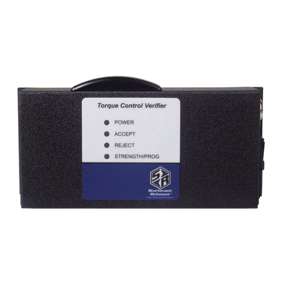
- Page 6 In normal operation this Light Emitting Diode (LED) will emit green, yellow, or red light. If the LED is green, the TCV is receiving a strong radio signal from the FM Switch Wrench that it is working with. If it is yellow the signal strength is marginal. If this LED is red than the signal strength is inadequate and the distance from the tool to the TCV should be reduced.
-
Page 7: Chapter 2 - Domestic Warnings (Usa)
5-Pin Connector This male connector connects wires from PLC’s and other line control devices to the pins on the mating receptacle on the TCV. The system is designed to work with 24VDC I/O devices. 15 9-Pin Serial Convertor This device attaches to the serial port on the computer that will run the software used to program the TCV. -
Page 8: Chapter 3 - Tcv Installation
3 Installation There are two separate processes for installation; the TCV must be installed in the location where it will be used and the software must be installed on the computer. Installation Electric Safety It is mandatory that the national, state, and local safety and wiring standards be adhered to during installation. - Page 9 Mounting the TCV This unit may be wall mounted, table mounted, beam mounted, suspended overhead, pedestal mounted, or used without mounting. Mounting tabs are located on flanges on the rear of the cabinet. The mounting location should be in a stable, secure area so as to avoid damage to the unit and avoid injury to the operator due to an inconvenient mounting.
- Page 10 6. Use the Power Cord to bring electric power from the source to the TCV. Check the Power Switch and make certain that it is in the “Off” or de-energized position. Connect one end of the cord to the TCV at the Power Entry Module and plug the other end into the electric outlet.
- Page 11 Software Installation and Computer Connection A compact disk packaged with each TCV contains the software required to program the unit. The software must be installed and used to program the TCV before the unit is placed in ser- vice. This software will work on machines using the Windows XP Professional operating system.
-
Page 12: Chapter 4 - Tool Communications
Since the TCV can only work with one torque wrench at a time, if a tool has already been learned by the unit the memory of that tool must be cleared should it become necessary for it to be used with a different wrench. - Page 13 TCV can also be used to associate the wrench with the TCV. RF Channels The TCV and SLTC-FM 2.4 GHz wrenches can operate on any one of 12 channels. If the channel is changed after a torque wrench has been associated with the TCV, the Clearing the Tool Memory procedure must be performed and the wrench must then again be put through the Creating the TCV Unit and Tool Association procedure above.
-
Page 14: Chapter 5 - Using Device Programmer Software To Program The Tcv
Sturtevant Richmont. It provides rapid and efficient programming of the varying specifications required to obtain the most from the products. 1. To use the software, connect the serial port of the computer to the serial port of the TCV via the supplied cable and adapter. - Page 15 11. Use the pulldown menu for Beep Settings to select how the beeper on the TCV is to operate. There are four options available. 12. Total is the total number of cycles since the unit was placed in service or last reset to zero.
- Page 16 Once all of the specifications have been typed into the appropriate areas, click on the Write Settings button in the lower right-hand corner of the window to send the settings to the TCV. When the transmission is complete, the software can be closed and the computer disconnect- ed from the TCV.
Need help?
Do you have a question about the TCV and is the answer not in the manual?
Questions and answers