Advertisement
Quick Links
Sturtevant Richmont
Global Reach. Local Support.
Sturtevant Richmont Div. of Ryeson Corp.
3203 N. Wolf Road Franklin Park, IL 60131
Phones: 847/455-8677 800/877-1347
Fax: 847/455-0347
E-Mail: CustomerService@srtorque.com
Web Site: www.srtorque.com
Operating Instructions
Torque Control Verifier 2.4 GHZ
S/R Part No. 10467
Manual P/N: 857269 Rev. A
This product is not RoHS compliant.
Advertisement

Subscribe to Our Youtube Channel
Related Manuals for Sturtevant Richmont 10467


Summary of Contents for Sturtevant Richmont 10467
- Page 1 Sturtevant Richmont Global Reach. Local Support. Sturtevant Richmont Div. of Ryeson Corp. 3203 N. Wolf Road Franklin Park, IL 60131 Phones: 847/455-8677 800/877-1347 Fax: 847/455-0347 E-Mail: CustomerService@srtorque.com Web Site: www.srtorque.com Operating Instructions Torque Control Verifier 2.4 GHZ S/R Part No. 10467 Manual P/N: 857269 Rev.
- Page 3 Table of Contents Contents Page Chapter 1 - Introduction ..........1 Chapter 2 - Domestic Warnings (USA) .
- Page 5 1 Introduction The TCV/FM Switch Wrench System is designed to assist the manufacturer in closing several gaps in the quality system that have hindered their quality improvement efforts. The key capabilities this system enables are: 1. The ability to integrate manual torque wrenches into the automated line control system. 2.
-
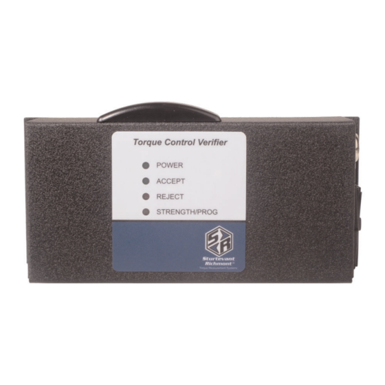
Page 6: Component Nomenclature
In use, the FM Switch Wrench tightens a fastener. As soon as the wrench clicks a timer on the wrench starts measuring time. When pressure on the wrench is released and the wrench resets, the timer stops and the duration of the click is transmitted to the TCV. The TCV compares the duration of the click to the TMIN and TMAX specification limits. - Page 7 Strength/Prog Light Emitting Diode (LED) In normal operation this Light Emitting Diode (LED) will emit green, yellow, or red light. If the LED is green, the TCV is receiving a strong radio signal from the FM Switch Wrench that it is working with. If it is yellow the signal strength is marginal. If this LED is red than the signal strength is inadequate and the distance from the tool to the TCV should be reduced.
- Page 8 This male connector connects wires from PLC’s and other line control devices to the pins on the mating receptacle on the TCV. The system is designed to work with 24VDC I/O devices. 15 9-Pin Serial Convertor This device attaches to the serial port on the computer that will run the software used to program the TCV.
-
Page 9: Installation
able protection against harmful interference in a residential installation. This equipment gener- ates, uses and can radiate radio frequency energy and if not installed and used in accor- dance with the instructions, may cause harmful interference to radio communications. However, there is no guarantee that interference will not occur in a particular installation. If this equipment does cause harmful interference to radio or television reception, which can be determined by turning the equipment off and on, the user is encouraged to try to correct the interference by one or more of thefollowing measures:... -
Page 10: Source Power
Mounting the TCV This unit may be wall mounted, table mounted, beam mounted, suspended overhead, pedestal mounted, or used without mounting. Mounting tabs are located on flanges on the rear of the cabinet. The mounting location should be in a stable, secure area so as to avoid damage to the unit and avoid injury to the operator due to an inconvenient mounting. -
Page 11: Connecting Peripheral Devices
3. Turn the red voltage selector/fuse holder over so the voltage matching that of the power to be supplied has the top of the printed voltage facing upwards. 4. Reinsert the red voltage selector/fuse holder into the module. The face of the voltage selector/fuse holder will be slightly recessed in the module when it has been properly reinserted. - Page 12 The circuit diagram below is that for the relays. The TCV Input/Output control system is designed primarily for use with 24VDC systems. Follow all national and state electrical codes and regulations when connecting peripheral devices to the TCV. Do not exceed the voltages and amperages shown above.
- Page 13 5 Programming the TCV with CLK_TUNE Software (V1.0) The CLK-TUNE software for programming the TCV performs all the functions necessary to set the parameters that determine whether an individual cycle (or click) of the wrench is acceptable or not. The software also manages the serial communications with the TCV unit. Before sending settings to the TCV it is necessary to connect the computer to the TCV using the supplied 9-Pin to phone cable convertor and the phone cable supplied with the unit.
- Page 14 ton one time to make this the active selection. The border of the box will become thick, as displayed in the image in this section. Type in the desired minimum duration of a wrench cycle (seconds). When the first value (whole seconds) is typed in, the numbers will move to the right side of the box and a small triangle will indicate the active number.
- Page 15 Download Button This button is used to download a set of parameters from the software to the TCV. File Button This button is used to store a parameter set for later use. The user can select the name of the parameter set for later recall. Get Parameter Set Button This button is used to retrieve a previously-stored parameter set.
Need help?
Do you have a question about the 10467 and is the answer not in the manual?
Questions and answers