
Related Manuals for Monroe Electronics ISOPROBE 279


Summary of Contents for Monroe Electronics ISOPROBE 279
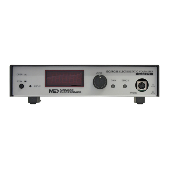
- Page 1 INSTRUCTION MANUAL ® ISOPROBE ELECTROSTATIC VOLTMETER MODEL 279 Equipment Included: Line Cord Manual Probe Cover Plug 279/100 P/N 0340112 110309...
- Page 2 Monroe Electronics. In the event of a breach of the foregoing warranty, the liability of Monroe Electronics shall be limited to repairing or replacing the non-conforming goods and/or defective work, and in accordance with the foregoing, Monroe Electronics shall not be liable for any other damages, either direct or consequential.
-
Page 3: Table Of Contents
MODEL 279 ® ISOPROBE ELECTROSTATIC VOLTMETER TABLE OF CONTENTS SPECIFICATIONS ................PAGE 1 INSTALLATION ................PAGE 3 III. CONTROLS AND INDICATORS ............PAGE 5 OPERATION ...................PAGE 7 THEORY ..................PAGE 8 ADJUSTMENT................PAGE 10 VII. TROUBLESHOOTING..............PAGE 14 APPENDIXES: MODEL 1034 PROBE MOUNTING..APPENDIX I……………………….Page 16 HV BREAKDOWN CONSIDERATIONS.. -
Page 4: Specifications
SECTION 1 SPECIFICATIONS Applications: ® Model 279 ISOPROBE ELECTROSTATIC VOLTMETER takes advantage of Monroe’s years of experience in design of reliable instruments for NON-CONTACTING measurement of electrostatic potential combined with modern semiconductor technology. A full spectrum of proven-design interchangeable probes exposes broad new areas for exploratory research as well as providing a precision instrument for routine applications in electrostatic measurements. - Page 5 PROBES: Monroe Electronics Type 1034E (end viewing) or 1034S (side-viewing) probes are 0.35” (9mm) x 0.35” (9mm) x 3.25” (82.6mm) in length. Add 0.8” (20mm) length for cable at minimum bend radius. Contains 1kHz tuning fork chopping driver and onboard hybrid microcircuit preamp.
-
Page 6: Installation
SECTION 2 INSTALLATION CAUTION: Before plugging instrument in, make certain that it is matched to local power line voltage. The factory set line voltage may be determined by the position of the voltage selector indicator pin in the power entry module. All units are shipped configured for 120 VAC unless otherwise specified. - Page 7 Probe purging improves instrument performance especially with regard to zero stability, noise and sensitivity to variations in probe-to-surface spacing. An optional purge kit available from Monroe Electronics maintains an even airflow, reduces temperature variations and filters out dust and other particles.
-
Page 8: Controls And Indicators
Probe receptacle: Mates with Model 1034 series probes manufactured by Monroe Electronics. An appropriate and functional probe must be connected for the instrument to operate. To connect the probe to the instrument, hold the plug (on probe cable) so that the two arrows are on top. Align with the receptacle and push straight in until a “click”... - Page 9 REAR PANEL - Figure 3-2 Power Entry Module: The Power Entry Module combines power inlet, switch and fusing system. Power supply voltage is usually factory preset for local conditions. When in doubt, check! See Appendix II for details. Ground jack: Instrument ground - the reference point for measurement.
-
Page 10: Operation
SECTION 4 OPERATION CAUTION: Verify that instrument operating voltage matches local power line voltage. Refer to power connector on rear panel to verify voltage the instrument is set for. PRECAUTIONARY NOTE Model 279 is a non-contacting voltmeter. The potential of the probe will attempt to follow the potential of any object within the field of view of the sensitive electrode (up to 3400 volts) when the instrument is operating. -
Page 11: Theory
SECTION 5 THEORY General: Principle of Operation (See Figure 5-1) The electrostatic electrode "looks" at the surface under measurement through a small hole at the base of the probe assembly. The chopped AC signal induced on this electrode is proportional to the differential voltage between the surface under measurement and the probe assembly. - Page 12 If, however there exist voltage sources in the vicinity of the sensitive electrode which are independent of the unknown to be measured, the offsets produced will detrimentally affect the spacing independence. Such voltage sources include contact potential differences among the internal probes parts, small specks of charged dust particles, etc.
-
Page 13: Adjustment
3570/22 and are identified in Table 6-2 at the end of this section. The procedure should be followed in the order given to prevent possible interaction of controls. A phase-compensated (normal) Monroe Electronics, Inc. Model 1034E or 1034S miniature probe must be used wherever the use of a probe is indicated. - Page 14 Probe Oscillator Adjustment: Connect an oscilloscope probe to TP5 and adjust R53 for a 6 Vp-p sine wave. Demodulator Phase Adjustment: 1. Move the oscilloscope probe to TP3 and adjust the ZERO 1 pot on the front panel for a null (straight line) on the oscilloscope.
- Page 15 Speed of Response: 1. Check that the probe to test plate spacing is still 1/8” (3,2mm). 2. Set the gain pot, front panel recessed, for about midrange. 3. Connect the oscilloscope to the rear panel output connector. 4. With the 279 in standby, STBY/OPER switch out, check the range of the ZERO 2 pot on the front panel meter.
- Page 16 Description NOTE HV TEST VM OPTion Driver link Standard output option selector Standard output option selector HV JUMPER Shorting plug, ME P/N 9231029 JP13 Red wire 1/1000 cal. SET 37 VDC OSCillator LEVEL INTegrator GAIN +BIAS -BIAS DEMODulator PHASE R107 Recessed through front panel GAIN R108...
-
Page 17: Troubleshooting
SECTION 7 TROUBLESHOOTING PRECAUTIONARY NOTE Model 279 is a non-contacting voltmeter. The potential of the probe will attempt to follow the potential of any object within the field of view of the sensitive electrode (up to 3400 volts) when the instrument is operating. - Page 18 Detailed Troubleshooting – Initial Setup: Follow instructions given in Section 6-C; Initial Setup and Adjustments leaving out Step 3 (potentiometer adjustments). NOTE: The following steps are done with the front panel OPER/STBY switch in STBY. Low Voltage Power Supplies: With a DVM, check between chassis ground and TP-16 and TP-15 for plus and minus 15 volts.
-
Page 19: Model 1034 Probe Mounting
APPENDIX I MODEL 1034 PROBE MOUNTING The Monroe Electronics, Inc. Model 1034 Miniature Probe is intentionally constructed with no mounting devices, as any such mounting device would serve only to enlarge the physical dimensions. It is, therefore, left to the user to devise a method of mounting the probe to suit his individual needs and to realize the fullest potential of the inherently small size. - Page 20 Figure A-I-1 Page 17...
-
Page 21: Hv Breakdown Considerations
APPENDIX II POWER ENTRY MODULE This instrument uses a Corcom, Inc. M Series Power Entry Module that combines a power inlet, switch and fusing system in one compact unit. The IEC 320 power inlet accepts any suitably terminated cordset. The ON/OFF switch is DPST and has international I/O markings. - Page 22 Fuse changing: Figure A-II-3a Figure A-II-3b European fusing arrangement North American fusing arrangement Figure A-II-4 Fuse block/cover assembly To change from North American to European fusing: open cover using a small blade screwdriver or similar tool; loosen Phillips screw 2 turns; remove fuse block by sliding up, then away from Phillips screw and lifting up from pedestal;...
- Page 23 APPENDIX III HV BREAKDOWN CONSIDERATIONS Air is subject to dielectric breakdown when the probe-to-surface spacing is small and the difference in voltage between the probe and the surface under test is high. A destructive arc-over can occur damaging the surface under test and/or the sensitive circuitry of the probe.
-
Page 24: Achieving Spacing Independence
APPENDIX IV ACHIEVING SPACING INDEPENDENCE Eliminating Zero Shift Over a Large Probe-to-Surface Spacing Range This instrument’s basic operating principle is to null the electric field between a surface under measurement and the sensitive electrode in the probe. When the potential of the surface under measurement is zero, the instrument drives the sensitive electrode and the probe housing (a reference surface) to zero potential, thereby nulling the electric field between the probe and the surface under measurement.
Need help?
Do you have a question about the ISOPROBE 279 and is the answer not in the manual?
Questions and answers