Table of Contents
Advertisement
Quick Links
Advertisement
Table of Contents

Related Manuals for Takeuchi TB210R


Summary of Contents for Takeuchi TB210R
- Page 2 All persons using this new one from your Takeuchi dealer. machine should thoroughly familiarize When transferring ownership of this machine, be sure to hand this manual to the next themselves with the contents of this manual.
- Page 3 SIGNAL WORDS IMPORTANT: The word IMPORTANT is used to alert operators and maintenance Safety messages appearing in this manual personnel about situations which could and on machine decals are identified by the result in damage to the machine and its words “DANGER”, “WARNING”...
-
Page 4: Introduction
If you have any questions about the spaces below. machine, please contact a Takeuchi sales or service outlet. Machine number: • Some details in this manual may differ from those provided in the machine you are using. -
Page 5: Machine Description
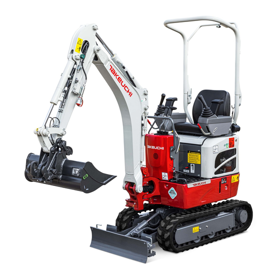
MACHINE DESCRIPTION FRONT, REAR, LEFT AND RIGHT FEATURES • “Flexible machine width mechanism” for FRONT crawler width • Low engine noise and exhaust emissions • Smaller rear slew radius, smaller turns (stability is retained) BREAK-IN PERIOD When the machine is new, operate the machine for the first 100 hours (as indicated LEFT RIGHT... - Page 6 NOTES ON READING THIS MANUAL Please note that the descriptions and diagrams included in this manual may not be applicable to your machine. The numbers used in the illustration are with circles around them. The same numbers appear between the parentheses in the text. (Example: (1)) Symbols used in this manual...
-
Page 7: Table Of Contents
CONTENTS Introduction ........0-2 Operation .........3-1 Before starting operation ......3-2 Machine description ......0-3 Getting on or off the machine ....3-2 Walk-around inspection ....... 3-2 Safety ..........1-1 Daily inspection ........3-2 General precautions ........ 1-2 Starting and stopping the engine ..... 3-3 Precautions when preparing .... - Page 8 Service data ..........5-4 Every 1000 hours ........5-38 Fuel and lubricant table ......5-4 Replacing the travel motor gear oil ..5-38 Regularly replace the hydraulic oil ..5-6 Cleaning the engine cooling system ... 5-38 List of consumables ......5-7 Replacing the air cleaner element ..
- Page 9 Biodegradable oil ........8-8 Replacing the hydraulic oil with biodegradable oil ......... 8-8 Travel alarm ..........8-9 Takeuchi Security System ...... 8-10 Starter key ......... 8-10 Starting the engine ......8-10 Registering and deleting the starter key.. 8-11 If the master key is lost ...... 8-12 Countries where the system can be used ..8-12...
-
Page 11: Safety
SAFETY... -
Page 12: General Precautions
SAFETY GENERAL PRECAUTIONS GENERAL PRECAUTIONS When a problem is found on the machine It is your responsibility to observe all If any problem (noise, vibration, smell, disorder of instrument, smoke, oil leak or pertinent laws and regulations and to follow the manufacture’s instructions on wrong indication of alarm and panel, etc.) is machine operation, inspection and detected during the operation or inspection... - Page 13 SAFETY GENERAL PRECAUTIONS Wear appropriate clothing and protective Install a fire extinguisher and first aid kit equipment AG7A005 Be prepared for fire and accidents AG7A004 • Do not wear loose clothing or any • Install an extinguisher and a first aid kit, accessory that can catch on controls or in and learn how to use them.
- Page 14 SAFETY GENERAL PRECAUTIONS Use a signal person and a flag person Cautions when standing up from or leaving the operator’s seat AG7A007 Learn how to use the hand signals required AG7A009 for particular jobs and make sure who has • Before standing up from the operator’s the responsibility for signaling.
- Page 15 SAFETY GENERAL PRECAUTIONS Avoid fire and explosion hazards • When handling the fuel, washing oil or paint, open the door and windows to ventilate thoroughly. • Store all flammable fluids and materials in a safe and well-ventilated place. • The short circuit of the electric system may cause the fire.
- Page 16 SAFETY GENERAL PRECAUTIONS Exhaust fumes from the engine are Be careful not to get crushed or cut poisonous AG7A013 Never put your hands, feet or other parts of AG7A011 • Do not operate the engine in an enclosed your body between the upperstructure and area without adequate ventilation.
- Page 17 Takeuchi. Doing so may compromise safety or adversely affect the machine’s operation or service life. • Takeuchi will not be held responsible for any injuries, accidents or damage to its products caused by the use by a non-...
-
Page 18: Precautions When Preparing
SAFETY PRECAUTIONS WHEN PREPARING PRECAUTIONS WHEN Check the strength of the bridge PREPARING When traveling over a bridge or a structure, check the permissible load. If the strength is Know the work area insufficient, reinforce the bridge or the structure. Before starting operation, know the working area condition to ensure safe operation. - Page 19 SAFETY PRECAUTIONS WHEN PREPARING Perform inspection and maintenance Cautions in the operator’s compartment every day • Remove mud and grease from shoe soles before entering the operator’s compartment. Pedaling the machine with the shoes with mud and grease will cause a slip accident.
-
Page 20: Precautions When Starting
SAFETY PRECAUTIONS WHEN STARTING PRECAUTIONS WHEN STARTING Support your weight in a three point secure stance when getting on/off the machine • Do not jump on or down from the machine. Never attempt to get on or off the moving machine. - Page 21 SAFETY PRECAUTIONS WHEN STARTING Starting with jumper cables In cold climates AG7A027 AG7A025 Use jumper cables only in the recommended • Be careful of slippery conditions on freezing manner. Improper use of jumper cables can ground, steps and hand holds. result in battery explosion or unexpected •...
-
Page 22: Precautions When Operating
SAFETY PRECAUTIONS WHEN OPERATING PRECAUTIONS WHEN • Unauthorized machine modifications or installation of unapproved attachments OPERATING could impair the visibility. The operator’s field of view must conform to ISO 5006. Operate the machine with the maximum crawler width Do not permit riders on the machine AD6A001 •... - Page 23 SAFETY PRECAUTIONS WHEN OPERATING Check the position of the undercarriage Travel safely (tracks) before traveling Dozer blade • Travel with the dozer blade raised, the hoe AG7A032PE Before operating the travel levers, make sure attachment folded as shown on the figure that the dozer blade is to the front of the above, and the bucket raised 30 to 40 cm operator’s seat.
- Page 24 SAFETY PRECAUTIONS WHEN OPERATING Cautions on traveling on slopes When traveling on slopes or grades, be careful that the machine does not tip (roll) over or slide. • Never travel on slopes that are too steep for the machine to maintain its stability. Note that in reality, the machine’s performance decreases on slopes due to its poor working condition.
- Page 25 SAFETY PRECAUTIONS WHEN OPERATING Operate the machine on snow or ice with Ensure driver’s safety when loading extra care • When traveling on snow or on frozen surfaces, drive at a low speed and avoid starting, stopping or changing directions abruptly.
- Page 26 SAFETY PRECAUTIONS WHEN OPERATING Keep a safe distance from the overhead high-voltage cables • Pay also careful attention to the high- voltage electric cables buried underground. AG7A041 Never bring any part of the machine or loaded material to near to the high voltage cables unless all safety precautions required by the local and national authorities have been installed.
- Page 27 SAFETY PRECAUTIONS WHEN OPERATING Watch out for hazardous working conditions • Do not enter areas where there is soft ground. Doing so could cause the machine to tilt under its own weight, resulting in a • Never undercut a high bank. Doing so is machine tipping over or sinking into the dangerous as it may cause ground ground.
- Page 28 SAFETY PRECAUTIONS WHEN OPERATING • Do not use the impact force of the hoe attachment for breaking work. There is a hazard of serious injury being caused by flying pieces of broken materials and by the damaged hoe attachment. Operating on slopes is dangerous When operating on slopes or grades, slewing or operation of working equipment may •...
- Page 29 SAFETY PRECAUTIONS WHEN OPERATING Never slew (swing) sideways with a heavy Excavators are not designed for lifting load loads AG7A054 The machine can tip over more easily in the This machine is specifically designed for lateral direction than in the longitudinal excavation work.
- Page 30 SAFETY PRECAUTIONS WHEN OPERATING Cautions when towing Be careful with flying objects This machine is not equipped with protective equipment to protect the operator from flying objects. Do not use this machine in places where there are risks of the operator being hit by flying objects.
-
Page 31: Precautions When Stopping
SAFETY PRECAUTIONS WHEN STOPPING PRECAUTIONS WHEN STOPPING Park safely AG7A060 • Before leaving the machine, do the followings: 1. Set the slew lock lever to the locked position. 2. Lower the bucket and the dozer blade to the ground. AG7A058 •... -
Page 32: Precautions When Transporting
SAFETY PRECAUTIONS WHEN TRANSPORTING PRECAUTIONS WHEN TRANSPORTING Load/unload the machine safely Ramp Stopper 15º or less Distance between ramps AG7F001PE The machine may roll or tip over or fall while being loaded or unloaded. Take the following precautions: • Select a firm, level surface and keep sufficient distance from road shoulders. - Page 33 SAFETY PRECAUTIONS WHEN TRANSPORTING Hoist the machine safely Transport the machine safely • Know and use correct crane signals. • Know and follow the applicable safety • Check the hoisting equipment for damaged rules, vehicle code and traffic laws when or missing parts on a daily basis and transporting the machine.
-
Page 34: Precautions On Maintenance
SAFETY PRECAUTIONS ON MAINTENANCE PRECAUTIONS ON Replace safety-critical parts periodically MAINTENANCE • Replace fuel hoses periodically. Fuel hoses wear out over time, even if they do not Display a “DO NOT OPERATE” alert sign show any symptom of wear. • Regardless of the replacement schedule, Severe injury could result if an unauthorized replace immediately if a symptom of wear person should start the engine or touch... - Page 35 SAFETY PRECAUTIONS ON MAINTENANCE Prohibit access by unauthorized persons Always keep the machine clean AG7A070 AG7A068 Do not allow unauthorized personnel in the • Clean the machine before performing work area while working. Be careful when maintenance. grinding, welding or using a hammer. You •...
- Page 36 SAFETY PRECAUTIONS ON MAINTENANCE Stay clear of the moving parts Secure the working equipment To prevent unexpected movement, firmly secure the working equipment when repairing or replacing the bucket teeth or side cutter. Secure the engine hood or cover when opened Be sure to secure the engine hood or cover before working the inside.
- Page 37 SAFETY PRECAUTIONS ON MAINTENANCE Cautions when refueling Be careful with hot and pressurized components • Do not smoke or permit open flames while AG7A081 fueling or near fueling operations. Stop the engine and allow the machine to • Never remove the fuel cap or add fuel cool down before performing maintenance.
- Page 38 SAFETY PRECAUTIONS ON MAINTENANCE Be careful with hot cooling systems Release pressure before working on the hydraulic system Oil may spurt out if caps or filters are removed or pipes are disconnected before releasing the pressure in the hydraulic system. •...
- Page 39 • If grease does not come out when the hitting, rolling or dropping. grease discharge valve is loosened, the • Before disposing of the unit, the sealed gas valve is faulty. Ask a Takeuchi service agent must be drained. Contact a Takeuchi for repair. service agent for help.
- Page 40 SAFETY PRECAUTIONS ON MAINTENANCE Disconnect the battery wiring Use caution when handling batteries • Batteries contain sulfuric acid which will damage the eyes or skin in case of contact. · If eye contact occurs, flush immediately with clean water and get prompt medical attention.
- Page 41 SAFETY PRECAUTIONS ON MAINTENANCE Periodically replace the safety-critical Jump starting with booster cables parts • When starting the engine using the booster • To use the machine safely for a longer cables, be sure to connect the cables in period, periodically add oil and perform the proper order described below.
- Page 42 SAFETY PRECAUTIONS ON MAINTENANCE Have a Takeuchi service agent repair Disposing of wastes welding If welding must be performed, make sure that it is done by a qualified person in a properly equipped workplace. To prevent any part from breaking down or being damaged due to overcurrent or sparks, observe the following.
-
Page 43: Safety Signs (Decals)
Please include your product serial number when ordering a new sign from the Takeuchi service agent. • When a part/unit to which a safety sign is attached is replenished, a new sign must be attached to the new part/unit. - Page 44 SAFETY SAFETY SIGNS (DECALS) 1-34...
- Page 45 SAFETY SAFETY SIGNS (DECALS) 1-35...
- Page 46 SAFETY SAFETY SIGNS (DECALS) 1-36...
- Page 47 SAFETY SAFETY SIGNS (DECALS) 1-37...
- Page 48 1-38...
-
Page 49: Controls
CONTROLS... -
Page 50: Names Of Components
CONTROLS NAMES OF COMPONENTS NAMES OF COMPONENTS Upperstructure Undercarriage Working equipment 1. Canopy 6. Crawler belt 11. Bucket 2. Seat 7. Idler 12. Bucket cylinder 3. Engine hood 8. Track roller 13. Arm 4. Fuel tank 9. Shoe slide 14. Arm cylinder 5. - Page 51 CONTROLS NAMES OF COMPONENTS 1. Instruments 10. Travel levers 2. Starter switch 11. Travel speed switch 3. Blade lever 12. Auxiliary hydraulic pedal 4. Throttle lever 13. Left operating lever 5. Safety lock levers 14. Slew lock lever 6. Right operating lever 15.
-
Page 52: Covers
CONTROLS COVERS COVERS MAINTENANCE COVER STARTER KEY Open this cover to perform a maintenance operation of the engine. Opening The starter key is used to start and stop the engine, as well as to lock and unlock the following components: •... -
Page 53: Fuel Lid
CONTROLS COVERS FUEL LID FUEL FILLER PORT When opening and closing the fuel lid, be • Do not smoke and keep away from heat careful not to get your hands caught by or flame while filling the fuel tank. the lid. •... -
Page 54: Engine Hood
CONTROLS COVERS ENGINE HOOD Opening • Before opening the engine hood, be sure to stop the engine. If a hand or tool becomes trapped in the rotating or moving part, serious injury could result. • Opening or closing the engine hood while the engine is running may cause the machine to move, resulting in serious injury or death. -
Page 55: Folding Down The Canopy
CONTROLS FOLDING DOWN THE CANOPY FOLDING DOWN THE CANOPY Do not operate the machine with the canopy folded down. The TOPS will not be applicable to the machine if the canopy is folded down. TOPS (ISO12117): Tip-over protection structure When folding down the upper canopy, be sure to lower it slowly. -
Page 56: Seat And Seat Belt
CONTROLS SEAT AND SEAT BELT SEAT AND SEAT BELT SEAT Adjust and secure the seat. Fore-and-aft adjustment 1. Pull up the lever (1) and slide the seat backward or forward to the desired position for operation of machine. 2. Release the lever (1) at the desired position to secure the seat. -
Page 57: Seat Belt
CONTROLS SEAT AND SEAT BELT SEAT BELT Releasing the seat belt Be sure to fasten the seat belt securely before starting the engine. Fastening the seat belt 1. Adjust the seat to the desired position for operation, sit up and sit back in the chair. 2. -
Page 58: Instruments
CONTROLS INSTRUMENTS INSTRUMENTS Once the starter switch is turned to ON, the battery charge warning lamp (1) and the engine oil pressure warning lamp (2) light up. The machine system is normal if the lamps turn off after the engine is started. If either lamp does not light up, there is something wrong in the machine. -
Page 59: Indicator
CONTROLS INSTRUMENTS INDICATOR METER 4. Travel speed lamp 5. Hour meter This lamp turns on when the travel speed Displays the total engine running time in button is set to the 2nd (high) speed. hours. The rightmost digit indicates tenths of hours (6 minutes). -
Page 60: Switches
CONTROLS SWITCHES SWITCHES TRAVEL SPEED SWITCH STARTER SWITCH Press this switch to set the travel speed to 2nd (high) speed. Press it again to return to IMPORTANT: Do not repeatedly switch 1st (low) speed. the key from OFF to ON and ON to OFF over a short period. -
Page 61: Boom Light
CONTROLS SWITCHES BOOM LIGHT When the switch is pressed while the starter switch is at ON, the light turns on or off as follows: O ..Off I ..On 2-13... -
Page 62: Levers And Pedals
CONTROLS LEVERS AND PEDALS LEVERS AND PEDALS Safety start function <Applicable machine models 211003145 or later> SAFETY LOCK LEVER When the lever is in the unlock position, the engine cannot be started. SLEW LOCK LEVER • Before standing up from the operator’s seat to, for example, adjust the operator’s seat, lower the working equipment to the ground, raise the... -
Page 63: Throttle Lever
CONTROLS LEVERS AND PEDALS THROTTLE LEVER BLADE LEVER This controls the engine speed. Use this lever to operate the dozer blade. (A) ..Low idling (A) ..Blade up (B) ..Maximum speed (B) ..Blade down Refer to “Operating the dozer blade” on page 3-17. -
Page 64: Travel Levers
CONTROLS LEVERS AND PEDALS TRAVEL LEVERS BOOM SWING PEDAL Before operating the travel levers, make Fold the pedal away when not in use. sure that the dozer blade is to the front of Stepping on a pedal accidentally when it the operator’s seat. -
Page 65: Auxiliary Hydraulic Pedal
CONTROLS LEVERS AND PEDALS AUXILIARY HYDRAULIC PEDAL 1. Fold the pedal away while it is being pushed into the side (A). 2. Pass the pedal hole through the bolt (1) to fasten the pedal. Fold the pedal away when not in use. 3. -
Page 66: Accessories
CONTROLS ACCESSORIES ACCESSORIES POWER SUPPLY SOCKET Use only those electric products which comply with the specifications of this socket. For beacon (If equipped) This socket is used to supply power. Be sure to use this socket for devices which require power supply voltage/current less than 12V/5A. -
Page 67: Auxiliary Hydraulic Lines
CONTROLS ACCESSORIES AUXILIARY HYDRAULIC LINES This line delivers the hydraulic oil necessary for operating a hydraulic breaker, crusher or other attachments. Oil may spurt out if pipes disconnected before releasing the pressure in the hydraulic system. (1) ..Auxiliary hydraulic line •... - Page 68 CONTROLS ACCESSORIES Connecting the hydraulic circuits Disconnecting the hydraulic circuits To connect the attachment hydraulic lines, 1. Release the pressure remaining in the observe the following procedures: lines, and then close the stop valve. 1. Release the pressure remaining in the Refer to “Releasing the residual pressure”...
- Page 69 CONTROLS ACCESSORIES Selector valve Open ..When using a hydraulic breaker (1-way flow) Close ..When using a reversible attachment (2-way flow) Change the direction of the hydraulic oil flow by opening or closing the selector valve (1) on the machine body. 2-21...
-
Page 70: Accumulator (If Equipped)
Lowering the boom when the engine has gas must be drained. Contact a stopped Perform this operation within 10 minutes Takeuchi service agent for help. after the engine stopping. For a machine with an accumulator, the 1. Check that the safety lock lever is in the residual pressure in the auxiliary hydraulic released position. -
Page 71: Operation
OPERATION... -
Page 72: Before Starting Operation
OPERATION BEFORE STARTING OPERATION BEFORE STARTING WALK-AROUND INSPECTION OPERATION Perform the walk-around inspections once a day before starting the engine for the first GETTING ON OR OFF THE MACHINE time that day. Refer to “MAINTENANCE, Walk-around inspection”, on pages 5-14 and 5-15. •... -
Page 73: Starting And Stopping The Engine
OPERATION STARTING AND STOPPING THE ENGINE STARTING AND STOPPING 5. Insert the key into the starter switch, turn it to the ON position, then perform the THE ENGINE following inspections: BEFORE STARTING THE ENGINE 1. Adjust the seat for a comfortable operating position. -
Page 74: Starting The Engine
OPERATION STARTING AND STOPPING THE ENGINE STARTING THE ENGINE When the machine is equipped with the safety start function: The engine does not start unless the safety lock lever is in the locked position at this point. • Clear all personnel from the work area. Refer to “Safety lock lever”... -
Page 75: Warming Up The Engine
OPERATION STARTING AND STOPPING THE ENGINE STOPPING THE ENGINE When the coolant temperature is –5 to 10°C (23 to 50°F). When the coolant temperature is at or IMPORTANT: Do not stop the engine below –5°C (23°F), hold it for about 10 suddenly when operating with heavy seconds for preheating. -
Page 76: Operating The Machine
OPERATION OPERATING THE MACHINE OPERATING THE MACHINE LEVER PATTERN (ISO PATTERN) • Before starting operation, carefully check which lever pattern you are going to use. • It is described using the ISO pattern in this manual. Left crawler forward Right crawler forward Left crawler reverse Right crawler reverse Arm out... -
Page 77: Lever Pattern (G Pattern) (If Equipped)
OPERATION OPERATING THE MACHINE LEVER PATTERN (G PATTERN) (IF EQUIPPED) • Before starting operation, carefully check which lever pattern you are going to use. • It is described using the ISO pattern in this manual. Left crawler forward Right crawler forward Left crawler reverse Right crawler reverse Boom lower... -
Page 78: Warming Up The Machine (Hydraulic Oil)
OPERATION OPERATING THE MACHINE WARMING UP THE MACHINE (HYDRAULIC OIL) Operating the working equipment without warming up the machine (hydraulic oil) is dangerous, as the working equipment cannot response to controls quickly or may move in unexpected ways, and the safety devices may not operate properly. -
Page 79: Inspection After Warm-Up
OPERATION OPERATING THE MACHINE INSPECTION AFTER WARM-UP After warming up the engine and machine (hydraulic oil), perform the checks and inspections described below, and repair if necessary. 5. Slew slowly to the left and the right several times. 1. Check that the warning lamps and meters are as follows: ·... -
Page 80: Crawler Width Switching
OPERATION OPERATING THE MACHINE CRAWLER WIDTH SWITCHING IMPORTANT: Be sure to raise the machine body before switching the crawler width. If the operation is attempted when the crawler is rested on the ground, the travel Operate the machine with the maximum frame or span cylinder may be damaged. -
Page 81: Switching The Blade Width
OPERATION OPERATING THE MACHINE SWITCHING THE BLADE WIDTH 4. Pull the blade lever toward you (A) to decrease the crawler width (750 mm or 29.5 in.). 1. Pull out the lock pin (1). 2. Rotate the plate (2). 3. Insert the lock pin (1) to secure the plate (2). -
Page 82: Operating The Travel Levers
OPERATION OPERATING THE MACHINE OPERATING THE TRAVEL LEVERS Moving the machine forward and backward • Never allow anyone to enter the machine’s slewing radius and path. • Signal your intention to move by sounding the horn. • There is a blind spot in the rear of the machine. - Page 83 OPERATION OPERATING THE MACHINE Traveling in 2nd (High) speed When the dozer blade is in front of the operator’s seat: To move forward: Press the travel speed switch on the right Tilt the levers forward. travel lever to switch to 2nd (high) speed, To move backward: and press it again to return to 1st (low) Tilt the levers backward.
- Page 84 OPERATION OPERATING THE MACHINE Pivot turn Spin turn Turning to the left when stopped: To spin left: To turn forward to the left: Tilt the left lever backward and the right Tilt the right lever forward. lever forward. To turn backward to the left: To spin right: Tilt the right lever backward.
-
Page 85: Stopping Travel
OPERATION OPERATING THE MACHINE STOPPING TRAVEL • Park the machine on a flat, rigid and safe ground. Set the parking brake. If you must park on a slope, chock the tracks to block the machine. • If any control is accidentally touched when the safety lock lever is not locked, the machine may suddenly move and cause serious injury or death. -
Page 86: Operating The Working Equipment
OPERATION OPERATING THE MACHINE OPERATING THE WORKING EQUIPMENT Slewing • Before starting operation, carefully Check the surrounding area for safety check which lever pattern you are going before slewing. to use. • It is described using the ISO pattern in this manual. - Page 87 OPERATION OPERATING THE MACHINE Operating the arm Operating the boom swing Arm in: Boom swing left: Tilt the left operating lever backward. Step on the toe side of the pedal. Arm out: Boom swing right: Tilt the left operating lever forward. Step on the heel side of the pedal.
-
Page 88: Operating Procedures
OPERATION OPERATING PROCEDURES OPERATING PROCEDURES Be gentle when using the hydraulic cylinder PROHIBITED OPERATIONS • Do not operate on bedrock (hard or soft). • Do not slew/swing while traveling. If you must operate the hoe attachment while traveling, operate at speeds slow enough so you have complete control at all times. - Page 89 OPERATION OPERATING PROCEDURES Do not drive piles with the bucket or dig Digging bedrock by banging the bucket For hard base rock, break the rock up into Doing so will shorten the service life of the small pieces with a breaker, etc., before hoe attachment.
- Page 90 OPERATION OPERATING PROCEDURES Caution on folding the hoe attachment Pay attention to the dozer blade when digging Be careful not to let the bucket to hit the dozer blade when the hoe attachment is When digging deeply with the dozer blade being folded.
-
Page 91: Cautions On Operating
• Never submerge the slew bearing or main directions abruptly. body in water or sand. If submerged, • When traveling in 2nd speed, do so with contact a Takeuchi service agent for the dozer blade at the front. inspection. 3-21... -
Page 92: Cautions On Traveling On Slopes
OPERATION OPERATING PROCEDURES CAUTIONS ON TRAVELING ON SLOPES Traveling posture on slopes Climbing slopes • Never travel on slopes that are too steep for the machine to maintain its 90°~110° stability. Note that in reality, the machine’s performance decreases on slopes due to its poor working condition. - Page 93 OPERATION OPERATING PROCEDURES Braking when descending slopes If the engine stops When descending slopes, the brakes are If the engine stops when descending a applied automatically once the travel levers slope, set the travel levers to the neutral are returned to the neutral position. position, stop the machine, then start the engine.
-
Page 94: Getting Out Of Mud
OPERATION OPERATING PROCEDURES GETTING OUT OF MUD OPERATIONS POSSIBLE WITH THIS MACHINE If the machine gets stuck in mud, use the procedure below to get it out. Excavating If one crawler is stuck 1. Set the dozer blade on the side opposite to the side you want to dig on. - Page 95 OPERATION OPERATING PROCEDURES Digging side drains Leveling Use the boom swing function to dig side 1. Bring the hoe attachment close to the ditches as shown in the figure. body. 2. Gradually remove the dirt from the side of the mound. Loading 3.
-
Page 96: Parking The Machine
OPERATION PARKING THE MACHINE PARKING THE MACHINE 3. Set the slew lock lever to the locked position. PARKING 4. Lower the bucket and the dozer blade to the ground. 5. Raise the safety lock lever to the locked position. 6. Stop the engine and remove the key. Refer to “Stopping the engine”... -
Page 97: Handling In Cold Climates
Inspect the battery. If it is discharging, • Replace the fuel and oil for all parts with contact a Takeuchi service agent to have the those specified in the “Fuel and lubricant battery recharged. table”. Refer to “Inspecting the battery fluid level Refer to “Fuel and lubricant table”... -
Page 98: Handling Rubber Crawlers
OPERATION HANDLING RUBBER CRAWLERS HANDLING RUBBER CRAWLERS Rubber crawlers have an inherent weakness, lack of strength, due to their use of rubber. Be sure to observe the prohibitions and cautions below to prevent the crawlers from being damaged or coming off. PROHIBITIONS •... -
Page 99: Cautions
OPERATION HANDLING RUBBER CRAWLERS CAUTIONS Observe the following cautions when operating the machine: • Rubber crawler belts are not as stable as steel crawler belts since the entire lugs are made of rubber. Be very careful when slewing and swinging sideways. •... - Page 100 OPERATION HANDLING RUBBER CRAWLERS • When climbing in reverse, do not change • Do not change directions when the crawler directions at the point where the slope belts are slack as shown in the figure. starts. • The rubber crawler belts will come off if the •...
-
Page 101: Transport
TRANSPORT... -
Page 102: Loading And Unloading
TRANSPORT LOADING AND UNLOADING LOADING AND UNLOADING When loading or unloading the machine, be sure to use ramps or a platform and follow the procedure below. The machine may roll or tip over or fall while being loaded or unloaded. Take the following precautions: •... - Page 103 TRANSPORT LOADING AND UNLOADING AG7F003 7. Drive the machine straight toward the ramps and travel up or down the ramps at 1st (low) speed, by following the signal from the signal person. 8. Load the machine at the specified position on the transporter.
-
Page 104: Hoisting The Machine
Do not move the machine over the heads of the persons. machine slowly again. IMPORTANT: This hoisting method applies to machines with standard specifications. The center of gravity differs according to the attachments and optional equipment installed. Contact your Takeuchi service agent for details. -
Page 105: Securing The Machine
TRANSPORT SECURING THE MACHINE SECURING THE MACHINE After loading the machine at the specified position, secure it as described below. Transporting posture 1. Lower the dozer blade. Precautions to be taken during 2. Lock the slewing operation. transportation 3. Extend the bucket cylinder and arm cylinder fully, and then lower the boom. -
Page 107: Maintenance
MAINTENANCE... -
Page 108: General
MAINTENANCE GENERAL GENERAL CAUTIONS ON MAINTENANCE MAINTENANCE OVERVIEW Do not perform any other inspection and maintenance works than those listed in this To keep the machine in good condition and manual. use if for a long period, perform the For works not listed in this manual, ask your inspection and maintenance properly and sales or a service dealer for help. - Page 109 MAINTENANCE GENERAL Clean the installation surfaces Cautions on handling of battery wiring When installing and removing parts, be sure • Disconnect the wiring from the both that the surfaces of contact of the parts are terminals (+ and –) on the battery before clean.
-
Page 110: Service Data
MAINTENANCE SERVICE DATA SERVICE DATA FUEL AND LUBRICANT TABLE Select the appropriate fuel, lubricant and grease according to the temperature by referring to the table below. • Regardless of the specified time, change the oil if it becomes too dirty or degraded. •... - Page 111 MAINTENANCE SERVICE DATA Lubricant Type by air temperature When to Location Type -4 14 32 50 68 86 104°F replace -20 -10 0 10 20 30 40°C Diesel engine oil Every 250 hrs. SAE 10W-30 Engine oil pan API: CF, CF-4, CG-4, after the initial SAE 15W-40 CH-4 or CI-4 class...
-
Page 112: Regularly Replace The Hydraulic Oil
MAINTENANCE SERVICE DATA Volume Engine cooling Hydraulic oil Travel reduction Engine oil pan Fuel tank system tank gear Upper limit 4.0 L (4.2 US qt.) System 0.33 L X 2 Level capacity 2.8 L (3.0 US qt.) 15 L (4.0 US gal.) 12 L (3.3 US gal.) (0.35 US qt.) X 2 Lower limit... -
Page 113: List Of Consumables
MAINTENANCE SERVICE DATA LIST OF CONSUMABLES Periodically replace consumables such as filters and elements according to the table below. System Item Part name Part No. When to replace Hydraulic oil Every 500 hrs after Cartridge 15510-20310 return filter the initial 50 hrs. Hydraulic system Air breather (if equipped) Applicable machine models:... -
Page 114: List Of Tools (If Equipped)
MAINTENANCE SERVICE DATA LIST OF TOOLS (IF EQUIPPED) Code Part name Part No. Remarks Spanner 19102-12081 10 - 12 Spanner 19102-12082 12 - 14 Spanner 19102-12083 13 - 17 Spanner (Box) 19102-12084 19 - 22 Spanner 16901-00013 Spanner 16900-01922 19 - 22 Spanner 16909-00026 Screwdriver... -
Page 115: List Of Tightening Torques
MAINTENANCE SERVICE DATA LIST OF TIGHTENING TORQUES Nuts and Bolts (for ISO strength category 10.9) Tighten nuts and bolts at the torques shown on the table below, unless otherwise specified. • The tightening torques used for the mounted plastic covers are not listed in the table below. Consult your sales or service dealer for details. -
Page 116: Safety-Critical Parts
MAINTENANCE SAFETY-CRITICAL PARTS SAFETY-CRITICAL PARTS To use the machine safely, periodically perform inspection and maintenance. The safety-critical parts listed below must be periodically replaced for an increased safety. Serious injury or a fire could result if they are worn or damaged. List of safety-critical parts Safety-critical parts to be replaced Unit... - Page 117 MAINTENANCE SAFETY-CRITICAL PARTS The material of the safety-critical part listed above tends to change over time and cause wear or deterioration. It is difficult to determine the degree of deterioration at the periodic inspection, and thus they need to be replaced with new ones after a certain time to maintain their proper performance even if they appear in good condition.
-
Page 118: Maintenance List
MAINTENANCE MAINTENANCE LIST MAINTENANCE LIST Inspection and maintenance item Page Walk-around inspection Inspecting by opening the engine hood and covers 5-14 Inspecting by walking around the machine 5-15 Inspecting while sitting in the operator’s seat 5-15 Daily inspection (every 10 hours) Inspecting and replenishing the coolant 5-16 Inspecting and replenishing the engine oil... - Page 119 MAINTENANCE MAINTENANCE LIST Inspection and maintenance item Page Every 500 hours Replacing the hydraulic oil return filter 5-37 Replacing the fuel filters 5-37 Every 1000 hours Replacing the travel motor gear oil* 5-38 Cleaning the engine cooling system 5-38 Replacing the air cleaner element 5-40 Replacing the air breather (If equipped) 5-41...
-
Page 120: Walk-Around Inspection
MAINTENANCE WALK-AROUND INSPECTION WALK-AROUND INSPECTION Perform the following inspections every day before starting the engine for the first time. • Before operating, perform the walk-around inspections and make repairs immediately where necessary. • Be sure to secure the engine hood or cover before working the inside. Do not keep the hood or cover open on a windy day or if the machine is parked on a slope. -
Page 121: Inspecting By Walking Around The Machine
MAINTENANCE WALK-AROUND INSPECTION INSPECTING BY WALKING AROUND THE INSPECTING WHILE SITTING IN THE MACHINE OPERATOR’S SEAT 4. Check lights for dirt, damage and burnt 13. Check the seat and seat belt for dirt or out bulbs. damage. 5. Check attachments and hoses for Check the operator’s seat for dirt, oil or damage. -
Page 122: Daily Inspection (Every 10 Hours)
MAINTENANCE DAILY INSPECTION (EVERY 10 HOURS) DAILY INSPECTION Inspection (EVERY 10 HOURS) Perform the following inspections every day before starting the engine for the first time. • Before operating, perform the daily inspections and make repairs immediately where necessary. • Be sure to secure the engine hood or cover before working the inside. -
Page 123: Inspecting And Replenishing The Engine Oil
MAINTENANCE DAILY INSPECTION (EVERY 10 HOURS) INSPECTING AND REPLENISHING THE Replenishing ENGINE OIL Stop the engine and allow the machine to cool down before performing maintenance. Inspection 1. Remove the oil filler cap (2). 2. Add oil up to between the upper limit (H) and the lower limit (L) of the dipstick (1). -
Page 124: Inspecting The Fuel Filter (Water Separator)
MAINTENANCE DAILY INSPECTION (EVERY 10 HOURS) INSPECTING THE FUEL FILTER INSPECTING THE FUEL LEVEL (WATER SEPARATOR) • Do not smoke or permit open flames • Do not smoke or permit open flames while handling fuel or working on the while handling fuel or working on the fuel system. -
Page 125: Inspecting The Hydraulic Oil Tank Level And Replenishing
MAINTENANCE DAILY INSPECTION (EVERY 10 HOURS) INSPECTING THE HYDRAULIC OIL TANK Replenishing LEVEL AND REPLENISHING Oil may spurt out if caps or filters are removed or pipes are disconnected before releasing the pressure in the hydraulic system. • Gradually loosen the vent plug to relieve tank pressure. - Page 126 MAINTENANCE DAILY INSPECTION (EVERY 10 HOURS) Pressurizing the hydraulic oil tank (If not equipped with the air breather) 1. Start the engine and run it at low speed. 2. With the vent plug (2) removed, set the safety lock levers to the released position. ·...
-
Page 127: Lubricating The Working Equipment
MAINTENANCE DAILY INSPECTION (EVERY 10 HOURS) LUBRICATING THE WORKING EQUIPMENT 1. Keep the machine configuration as shown in the diagram above, lower the working equipment to the ground, and then stop the engine. 2. Use the grease gun to lubricate the grease fittings. 3. -
Page 128: After The Initial 50 Hours (Only For New Machines)
MAINTENANCE AFTER THE INITIAL 50 HOURS (ONLY FOR NEW MACHINES) AFTER THE INITIAL 50 1. Open the engine hood and the maintenance cover. HOURS (ONLY FOR NEW 2. Remove the oil filler cap (2). MACHINES) REPLACING THE ENGINE OIL AND THE OIL FILTER Stop the engine and allow the machine to cool down before performing... - Page 129 MAINTENANCE AFTER THE INITIAL 50 HOURS (ONLY FOR NEW MACHINES) 7. Turn the filter (5) counterclockwise with the filter wrench and remove it. 8. Clean the surface of installation of the filter stand. 9. Apply a thin layer of oil on the packing of the new filter.
-
Page 130: Inspecting And Adjusting The Fan Belt
MAINTENANCE AFTER THE INITIAL 50 HOURS (ONLY FOR NEW MACHINES) INSPECTING AND ADJUSTING THE FAN Adjustment BELT Stop the engine and allow the machine to cool down before performing maintenance. • The engine, muffler, radiator, hydraulic lines, sliding parts and many other parts of the machine are hot immediately after the engine is stopped. -
Page 131: Replacing The Hydraulic Oil Return Filter
MAINTENANCE AFTER THE INITIAL 50 HOURS (ONLY FOR NEW MACHINES) REPLACING THE HYDRAULIC OIL RETURN FILTER • Stop the engine and allow the machine to cool down before performing maintenance. · The engine and the hydraulic system and many other parts of the machine are hot immediately after the engine is stopped. -
Page 132: Every 50 Hours
Operate the levers slowly. · If grease does not come out when the grease discharge valve is loosened, the valve is faulty. Ask a Takeuchi service agent for repair. 3. Inspect the gap between the bottom surface of the frame at the center of the crawler frame and the top surface of the crawler. - Page 133 MAINTENANCE EVERY 50 HOURS Adjustment Decreasing the tension Increasing the tension 1. Remove the cover (1). 2. Slowly loosen (one turn) the grease 1. Remove the cover (1). discharge valve (2) with a spanner to 2. Inject grease through the grease fitting (3) discharge grease.
-
Page 134: Lubricating The Slew Bearing
MAINTENANCE EVERY 50 HOURS LUBRICATING THE SLEW BEARING LUBRICATING THE SLEW MOTOR PINION Do not slew while lubricating. Doing so is dangerous, as you may get caught in the machine. 1. Stop the engine with the machine in the posture shown on the figure above. 2. -
Page 135: Draining The Water From The Fuel Tank
MAINTENANCE EVERY 50 HOURS DRAINING THE WATER FROM THE FUEL Bleeding air from the fuel system TANK Refer to “Bleeding air from the fuel system” on page 6-8. Note: Air in the fuel system causes the • Do not smoke or permit open flames engine to fail to start or to have problems. -
Page 136: Inspecting The Battery Fluid Level And Replenishing
MAINTENANCE EVERY 50 HOURS INSPECTING THE BATTERY FLUID LEVEL Inspection AND REPLENISHING IMPORTANT: Check the fluid level of all cells following the steps below, even when the fluid level can be checked using • Do not use the battery when the fluid the indicator. - Page 137 MAINTENANCE EVERY 50 HOURS Replenishing When adding distilled water, do so before starting operations in order to prevent freezing. 1. Upon expiration of the warranty period, remove the label from the sealing plugs (3). 2. Loosen the sealing plugs (3) and add distilled water up to the highest level line (H).
-
Page 138: Every 100 Hours
MAINTENANCE EVERY 100 HOURS EVERY 100 HOURS CLEANING THE FUEL FILTER • Do not smoke or permit open flames while handling fuel or working on the fuel system. • Stop the engine in a well-ventilated place and allow it to cool down before performing maintenance. -
Page 139: After The Initial 250 Hours (Only For New Machines)
MAINTENANCE AFTER THE INITIAL 250 HOURS (ONLY FOR NEW MACHINES) AFTER THE INITIAL 250 1. Set the travel motor so that plug (1) is at the very bottom. HOURS (ONLY FOR NEW 2. Place a pan under the plug (1). 3. -
Page 140: Every 250 Hours
MAINTENANCE EVERY 250 HOURS EVERY 250 HOURS REPLACING THE ENGINE OIL AND THE OIL FILTER Refer to “Replacing the engine oil and the oil filter” on page 5-22. INSPECTING AND ADJUSTING THE FAN BELT 1. Open the fuel lid. Refer to “Inspecting and adjusting the fan 2. - Page 141 MAINTENANCE EVERY 250 HOURS 7. Clean the primary element (3) with dried compressed air (294 to 490 kPa or 43 to 71 psi). First blow the air from the inside of the element along the pleats. Then blow the air from the outside and finally from the inside again.
-
Page 142: Cleaning The Radiator Fins
MAINTENANCE EVERY 250 HOURS CLEANING THE RADIATOR FINS Wear required appropriate equipment such as protective goggle and filter mask when using compressed air, as metal fragments or other objects can fly and cause serious injury. IMPORTANT: Be careful not to damage the fins when cleaning. -
Page 143: Every 500 Hours
MAINTENANCE EVERY 500 HOURS EVERY 500 HOURS Pre-fuel filter (If equipped) REPLACING THE HYDRAULIC OIL RETURN FILTER Refer to “Replacing the hydraulic oil return filter” on page 5-25. REPLACING THE FUEL FILTERS 1. Open the fuel lid. • Do not smoke or permit open flames 2. -
Page 144: Every 1000 Hours
MAINTENANCE EVERY 1000 HOURS EVERY 1000 HOURS • Do not remove the radiator cap or the drain plug when the cooling water is REPLACING THE TRAVEL MOTOR GEAR hot. Stop the engine and wait until the engine and the cooling water cool. Then, slowly loosen the radiator cap Refer to “Replacing the travel motor gear oil”... - Page 145 MAINTENANCE EVERY 1000 HOURS 7. Close the radiator cap (3). 8. Start the engine and run it at a speed slightly above low idling. Raise the water temperature to at least 90°C (194°F), and then run the engine for about 10 minutes with the thermostat open.
-
Page 146: Replacing The Air Cleaner Element
MAINTENANCE EVERY 1000 HOURS REPLACING THE AIR CLEANER ELEMENT 5. Cover the intake hole at the back of the body (4) with cloth or tape to prevent dirt from getting in. <If equipped with the secondary element> Stop the engine and allow the machine to Do not yet remove the secondary element cool down before performing (5). -
Page 147: Replacing The Air Breather (If Equipped)
MAINTENANCE EVERY 1000 HOURS REPLACING THE AIR BREATHER (IF INSPECTING AND ADJUSTING THE EQUIPPED) ENGINE VALVE CLEARANCE This operation requires experience. Ask your service dealer for it. Oil may spurt out if caps or filters are removed or pipes are disconnected before releasing the pressure in the hydraulic system. -
Page 148: Every 1500 Hours
MAINTENANCE EVERY 1500 HOURS EVERY 1500 HOURS INSPECTING AND CLEANING THE ENGINE FUEL INJECTION NOZZLE This operation requires experience. Ask your sales or service dealer for it. 5-42... -
Page 149: Every 2000 Hours
MAINTENANCE EVERY 2000 HOURS EVERY 2000 HOURS REPLACING THE HYDRAULIC OIL AND CLEANING THE SUCTION STRAINER • Stop the engine and allow the machine to cool down before performing maintenance. · The engine and the hydraulic system and many other parts of the machine 3. - Page 150 MAINTENANCE EVERY 2000 HOURS 14. Install the suction strainer (8). 15. Install the flange (7). 16. Tighten the drain plug (6). 17. Add hydraulic oil from the hole of plug (2) up to the midpoint of the sight gauge (1). 18.
-
Page 151: Every 3000 Hours
MAINTENANCE EVERY 3000 HOURS EVERY 3000 HOURS INSPECTING THE FUEL INJECTION PUMP This operation requires experience. Ask your sales or service dealer for it. 5-45... -
Page 152: When Required
MAINTENANCE WHEN REQUIRED WHEN REQUIRED Removing REPLACING THE BUCKET • Before performing maintenance or repairs under the machine, lower all working equipment to the ground or in the lowermost position. • If maintenance must be performed with the engine running, always work as a two person team communicating each 1. - Page 153 MAINTENANCE WHEN REQUIRED Installation 1. Align the pin hole (A) on the bucket with the pin hole on the arm (5), and install the pin (2). 2. Operate the cylinder, align the pin hole (B) on the bucket with the pin hole on the link arm (6), and install the pin (2).
-
Page 154: Lubricating The Levers
MAINTENANCE WHEN REQUIRED LUBRICATING THE LEVERS Set the machine to the parking posture, stop the engine, remove the starter key and store it. Failure to do so may result in the machine moving abruptly, leading to serious injury or death. If the levers or pedals no longer move smoothly, grease them. -
Page 155: Inspecting The Rubber Crawlers
MAINTENANCE WHEN REQUIRED INSPECTING THE RUBBER CRAWLERS (3) Metal core Repair or replace the rubber crawlers if their condition becomes as described below. Consult your sales or service dealer for repair or replacement. Rubber crawler Replace the crawler if the entire crawler is stretched and cannot be adjusted. -
Page 156: Replacing The Rubber Crawlers
MAINTENANCE WHEN REQUIRED REPLACING THE RUBBER CRAWLERS Removal 1. Fully release the tension of the rubber crawler. Refer to “Inspecting and adjusting the • If you must work beneath the raised crawler tension” on page 5-26. machine or working equipment, always use wood blocks, jack-stands or other rigid and stable supports. - Page 157 MAINTENANCE WHEN REQUIRED Installation 1. Use the working equipment to lift the body. 2. Set the rubber crawler on the sprocket. 3. Set an iron pipe (1) in the rubber crawler and turn the sprocket slowly in the reverse direction. 4.
-
Page 158: Maintenance During Extended Storage Period
MAINTENANCE MAINTENANCE DURING EXTENDED STORAGE PERIOD MAINTENANCE DURING Starting the machine after storage EXTENDED STORAGE PERIOD IMPORTANT: If the above “Storage procedures” have not been followed Storage procedures during the extended storage periods, If the machine is to be stored for 30 days or consult your sales or service dealer more, store it indoors. -
Page 159: Troubleshooting
TROUBLESHOOTING... -
Page 160: Symptoms That Are Not Malfunctions
TROUBLESHOOTING SYMPTOMS THAT ARE NOT MALFUNCTIONS SYMPTOMS THAT ARE NOT • It becomes less easy to operate the machine when an attachment weighing MALFUNCTIONS more than a standard arm or bucket is installed. The symptoms listed below are not malfunctions. AG7J002 •... -
Page 161: If The Engine Overheats
TROUBLESHOOTING IF THE ENGINE OVERHEATS IF THE ENGINE OVERHEATS Remedy procedure 1. Park the machine in a safe place. 2. Check if steam is coming out of the closed engine hood and covers. • Do not open the engine hood and 3. -
Page 162: If The Battery Goes Dead
TROUBLESHOOTING IF THE BATTERY GOES DEAD IF THE BATTERY GOES DEAD Connecting the jumper cables The symptoms below indicate that the IMPORTANT: Set the starter keys of the battery is dead. booster vehicle and the dead machine to • The starter motor does not turn or fails to the OFF position. - Page 163 TROUBLESHOOTING IF THE BATTERY GOES DEAD Disconnecting the jumper cables Once the dead machine is successfully running, remove the jumper cables by following the same steps as for connection in the reverse order. 1. Disconnect the clip of jumper cable (B) from the engine block of the dead machine.
-
Page 164: If A Fuse Blows
TROUBLESHOOTING IF A FUSE BLOWS IF A FUSE BLOWS Fuse layout and circuits protected If a light does not come on or the electrical Protected Capacity Symbol system does not work, a fuse may be blown. circuit Inspect the fuses. Horn INSPECTING AND REPLACING THE FUSE Engine stop... -
Page 165: Inspecting The Fusible Link
TROUBLESHOOTING IF A FUSE BLOWS INSPECTING THE FUSIBLE LINK If the machine is not turned on after turning the starter switch to the ON position, the cartridge type fusible link (1) is likely blown. Open the engine hood and inspect. If the fusible link is blown, please contact your sales or service dealer. -
Page 166: Restarting After Adding Fuel
TROUBLESHOOTING RESTARTING AFTER ADDING FUEL RESTARTING AFTER ADDING For machines without a pre-fuel filter FUEL BLEEDING AIR FROM THE FUEL SYSTEM IMPORTANT: NEVER use the starter motor to crank the engine in order to prime the fuel system. This may cause the starter motor to overheat and damage the coils, pinion gear and/or ring gear. - Page 167 TROUBLESHOOTING RESTARTING AFTER ADDING FUEL For machines with a pre-fuel filter 3. Turn the starter key to the ON position and hold it for about 60 seconds. 1. Add fuel. The automatic air bleeder bleeds air from the fuel system. Note: Air in the fuel system causes the engine to fail to start or to have other problems.
-
Page 168: If A Warning Lamp Lights Up
TROUBLESHOOTING IF A WARNING LAMP LIGHTS UP IF A WARNING LAMP LIGHTS UP If a warning lamp lights up during operation, park the machine in a safe place and perform the procedures described below. Warning lamp Lamp name Causes and remedies Battery charge There is a problem with the fan belt or charger. -
Page 169: Other Symptoms
TROUBLESHOOTING OTHER SYMPTOMS OTHER SYMPTOMS For symptoms not included in the table below or if the problem persists after the proper remedies have been taken, consult your sales or service dealer. Symptoms Major causes Remedies Left and right operating levers •... - Page 170 TROUBLESHOOTING OTHER SYMPTOMS Symptoms Major causes Remedies Slewing is not possible or not • Slew lock lever lock is not • Release the slew lock lever smooth released • Insufficient grease on slew • Grease the bearing. bearing Refer to page 5-28. Hydraulic oil temperature is •...
- Page 171 TROUBLESHOOTING OTHER SYMPTOMS Symptoms Major causes Remedies Engine exhaust is white or • Excessive engine oil • Adjust to the specified level. bluish Refer to page 5-17. • Insufficient engine warm-up. • Perform the warm-up operation. Refer to page 3-5. •...
-
Page 172: Lowering The Boom To The Ground
TROUBLESHOOTING LOWERING THE BOOM TO THE GROUND LOWERING THE BOOM TO • Do not loosen or remove the hoses not located in the specified places. Oil may THE GROUND spurt out if wrongly handled. If the hoe attachment must be lowered to the ground while the engine is stopped, use the following procedure. -
Page 173: Towing
TROUBLESHOOTING TOWING TOWING Towing the machine Use the procedure described below to tow heavy objects or the machine itself if it should get stuck in the mud and not be able When towing, serious injury or death to get out on its own. could result, if performed incorrectly or the wire rope being used is inappropriate or not properly inspected. -
Page 174: If The Canopy Is Damaged
TROUBLESHOOTING IF THE CANOPY IS DAMAGED IF THE CANOPY IS DAMAGED Immediately replace the damaged canopy. Serious injury or death could occur if the machine is operated with damaged canopy. Do not operate the machine until the replacement is complete. Do not try to repair the damaged canopy by welding. -
Page 175: Specifications
SPECIFICATIONS... -
Page 176: Basic Specifications
SPECIFICATIONS BASIC SPECIFICATIONS BASIC SPECIFICATIONS Type Canopy MASS Operating mass kg (lb) Rubber crawlers 1150 (2535) PERFORMANCE Heaped 0.022 (0.76) Bucket capacity (cu. ft.) (Standard bucket) Struck 0.016 (0.57) Slew speed (rpm) 10 (10) 2.0 (1.24) Travel speed km/h (mph) Rubber crawlers 3.7 (2.30) Gradeability (degrees) - Page 177 MEMO...
-
Page 178: Machine Dimensions
SPECIFICATIONS MACHINE DIMENSIONS MACHINE DIMENSIONS... - Page 179 SPECIFICATIONS MACHINE DIMENSIONS Unit: mm (inch) Item Rubber crawlers Overall length 2955 (116.3) Upperstructure overall width 750 (29.5) Overall height 2190 (86.2) Slew radius 610 (24.0) Clearance height under upperstructure 395 (15.6) Crawler base 1005 (39.6) Crawler overall length 1325 (52.2) Crawler overall width (narrow) 750 (29.5) Crawler overall width (wide)
- Page 180 SPECIFICATIONS MACHINE DIMENSIONS Limited boom swing angle type...
- Page 181 SPECIFICATIONS MACHINE DIMENSIONS Limited boom swing angle type Unit: mm (inch) Item Rubber crawlers Overall length 2955 (116.3) Upperstructure overall width 750 (29.5) Overall height 2190 (86.2) Slew radius 610 (24.0) Clearance height under upperstructure 395 (15.6) Crawler base 1005 (39.6) Crawler overall length 1325 (52.2) Crawler overall width (narrow)
-
Page 182: Operating Ranges
SPECIFICATIONS OPERATING RANGES OPERATING RANGES... - Page 183 SPECIFICATIONS OPERATING RANGES Unit: mm (inch) Item Rubber crawlers Maximum reach 3285 (129.3) Maximum reach at ground reference plane 3220 (126.8) Maximum digging depth 1755 (69.1) Maximum vertical digging depth 1475 (58.1) Reach at maximum vertical digging depth 2265 (89.2) Maximum height of cutting edge 2985 (117.5) Maximum dumping height...
- Page 184 MEMO 7-10...
-
Page 185: Lifting Capacities
SPECIFICATIONS LIFTING CAPACITIES LIFTING CAPACITIES Rated lift capacity chart • Do not attempt to lift or hold any load • The loads in the charts do not exceed 87% that is greater than these rated values at of hydraulic lift capacity or 75% of tipping their specified load radii and height. - Page 186 SPECIFICATIONS LIFTING CAPACITIES 7-12...
- Page 187 SPECIFICATIONS LIFTING CAPACITIES 7-13...
- Page 188 7-14...
-
Page 189: Options
OPTIONS... -
Page 190: General Precautions
CAUTIONS WHEN INSTALLING attachment or optional part, take the ATTACHMENTS following precautions. • Consult with Takeuchi before installing an optional attachment. Be sure to perform a test operation after an • Do not use any attachments not optional or other special attachment has approved by Takeuchi. -
Page 191: Cautions When Operating Attachments
OPTIONS GENERAL PRECAUTIONS CAUTIONS WHEN OPERATING • Slewing on slopes ATTACHMENTS • If there is a heavy attachment is installed, the machine takes longer distance than usual to come to a complete stop when the stopping Long attachments reduce stability of the operation is performed. -
Page 192: Attachment Combination Table
• Consult with Takeuchi before installing an optional attachment. • Do not use any attachments not approved by Takeuchi. Doing so may cause safety problems. Or, it may adversely affect the machine’s operation or service life. • We will not be held responsible for any injuries, accidents or damage to its products caused by the use by a non-approved attachment. -
Page 193: Selecting A Lever Pattern
OPTIONS SELECTING A LEVER PATTERN SELECTING A LEVER PATTERN The operating pattern of the left and right operating levers can be changed. Before starting the engine, check the selector to see which operating pattern the left and right operating levers are set. SWITCHING THE LEVER PATTERN 1. -
Page 194: Hydraulic Breaker
OPTIONS HYDRAULIC BREAKER HYDRAULIC BREAKER Cautions on operating For handling of the breaker, read the hydraulic breaker’s manual, provided separately. • Start the engine and run it at 75% of the maximum speed. AD6A001 Do not use the breaker when the crawler width is narrowed! •... -
Page 195: Replacing The Hydraulic Oil Regularly
OPTIONS HYDRAULIC BREAKER REPLACING THE HYDRAULIC OIL REGULARLY When a hydraulic breaker is used, the oil deteriorates more quickly than that used for a usual operation. Be sure to replace the hydraulic oil and the return filter elements. • Failure to replace these in time can lead to damage to the machine and the breaker hydraulic system. -
Page 196: Biodegradable Oil
Have it performed by a Takeuchi sales or service outlet. Flushing To be performed by a Takeuchi sales or service outlet 1. Drain the hydraulic oil (mineral oil) from the hydraulic oil tank and clean the inside of the tank and suction strainer. -
Page 197: Travel Alarm
OPTIONS TRAVEL ALARM TRAVEL ALARM Fuse layout and circuits protected The alarm sounds while the machine is Protected Capacity Symbol traveling and stops when the machine stops circuit traveling. Horn If the alarm does not sound when the machine travels, the fuse may be blown. Engine stop Inspect the fuses. -
Page 198: Takeuchi Security System
OPTIONS TAKEUCHI SECURITY SYSTEM TAKEUCHI SECURITY SYSTEM STARTING THE ENGINE The Takeuchi Security System is a system that allows only registered starter keys to be used for starting the engine. The engine cannot be started with any unregistered or counterfeit starter keys. If a... -
Page 199: Registering And Deleting The Starter Key
OPTIONS TAKEUCHI SECURITY SYSTEM REGISTERING AND DELETING THE If an attempt is made to start the engine STARTER KEY with an unregistered key: If an unregistered starter key is turned from To register or delete the starter key, use a the OFF to the ON (ACC) position, the alarm tool specifically designed for this purpose. -
Page 200: If The Master Key Is Lost
COUNTRIES WHERE THE SYSTEM CAN BE USED To use the Takeuchi Security System, “radio wave authentication” must be obtained in the country where the system is to be used. The system can be used in the countries listed below, as of January 2017. -
Page 201: Adjustable Lever Stands
OPTIONS ADJUSTABLE LEVER STANDS ADJUSTABLE LEVER STANDS By spreading the lever stands to the left and right, you can have more space for your knees and thighs. Move the lever stands to where you want to secure them. Operating the machine without securing the lever stands could result in an accident. - Page 202 First Published July 2015 Thirteenth Published July 2019 AB8E012 OPERATOR’S MANUAL TB210R Mini excavator Edited and issued by TAKEUCHI MFG. CO., LTD. Printed in Japan by STATION M Co., Ltd. 8-14...
- Page 203 8-15...
- Page 204 EU directives. In case of any alteration of the machine not coordinated with us, this certificate loses its validity. Designation of the machine Compact Excavator Manufacturer TAKEUCHI MFG. CO., LTD 205 Uwadaira, Sakaki-machi, Hanishina-gun, Nagano 389-0605, Japan Model TB210R Engine type D722-EF13 (e1*2016/1628*2016/1628EV2/D*0008*∆)
- Page 205 WARNING: Breathing diesel engine exhaust exposes you to chemicals known to the State of California to cause cancer and birth defects or other reproductive harm. • Always start and operate the engine in a well-ventilated area. • If in an enclosed area, vent the exhaust to the outside. •...
Need help?
Do you have a question about the TB210R and is the answer not in the manual?
Questions and answers