
Subscribe to Our Youtube Channel
Related Manuals for Takeuchi TB295W


Summary of Contents for Takeuchi TB295W
- Page 2 All persons using this new one from your Takeuchi dealer. machine should thoroughly familiarize When transferring ownership of this machine, be sure to hand this manual to the next themselves with the contents of this manual.
- Page 3 SIGNAL WORDS IMPORTANT: The word IMPORTANT is used to alert operators and maintenance Safety messages appearing in this manual personnel about situations which could and on machine decals are identified by the result in damage to the machine and its words “DANGER”, “WARNING”...
- Page 4 If you have any questions about the machine, please contact a Takeuchi sales or service outlet. MANUAL STORAGE COMPARTMENT SERIAL NUMBERS A compartment for storing this manual is...
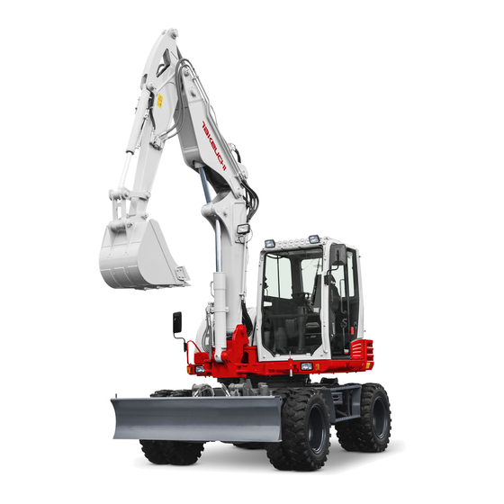
- Page 5 MACHINE DESCRIPTION FRONT, REAR, LEFT AND RIGHT DESIGNATED OPERATIONS Use this machine primarily for the following operations: • Excavation • Digging ditches • Digging side ditches • Leveling • Loading FEATURES • Adopting the auto-idle enables less fuel consumption • Engine emergency stop system •...
- Page 6 NOTES ON READING THIS MANUAL Please note that the descriptions and diagrams included in this manual may not be applicable to your machine. The numbers used in the illustration are with circles around them. The same numbers appear between the parentheses in the text. (Example: (1)) Symbols used in this manual...
- Page 7 CONTENTS Deceleration button ......2-35 Introduction ........0-2 Travel select button ......2-35 Auxiliary 1st switches ......2-36 Machine description ......0-3 Auxiliary 2nd /4th switch (If equipped) 2-36 Outrigger switches (If equipped) ..2-37 Safety ..........1-1 Third auxiliary hydraulic switch and button General precautions ........
- Page 8 Service data ..........5-4 Operation .........3-1 Fuel and lubricant table ......5-4 Before starting operation ......3-2 Regularly replace the hydraulic oil ..5-8 Getting on or off the machine ....3-2 List of consumables ......5-9 Walk-around inspection ....... 3-2 List of tools (If equipped) ....
- Page 9 Replacing the engine oil and the oil Every 4500 hours ........5-68 filter ........... 5-40 Inspecting the turbocharger Inspecting and adjusting the V-belt ..5-40 (blow wash as necessary) ....5-68 Inspecting and adjusting the Inspecting and cleaning the EGR compressor belt (AC) ......
- Page 10 Operating ranges ........7-8 Lifting Capacities ........7-11 Options ..........8-1 General precautions ........ 8-2 Safety precautions ....... 8-2 Cautions when installing attachments .. 8-2 Cautions when operating attachments . 8-3 Attachment combination table ....8-4 Selecting a lever pattern ......8-5 Switching the lever pattern ....
- Page 11 SAFETY...
- Page 12 SAFETY GENERAL PRECAUTIONS GENERAL PRECAUTIONS When a problem is found on the machine It is your responsibility to observe all If any problem (noise, vibration, smell, disorder of instrument, smoke, oil leak, pertinent laws and regulations and to follow the manufacture’s instructions on wrong indication of alarm or unusual machine operation, inspection and indication in the instrument cluster, etc.) is...
- Page 13 SAFETY GENERAL PRECAUTIONS Wear appropriate clothing and protective Install a fire extinguisher and first aid kit equipment Be prepared for fire and accidents • Do not wear loose clothing or any • Install an extinguisher and a first aid kit, accessory that can catch on controls or in and learn how to use them.
- Page 14 SAFETY GENERAL PRECAUTIONS Use a signal person and a flag person Cautions when standing up from or leaving the operator’s seat AG7A007 Learn how to use the hand signals required AG7A009 for particular jobs and make sure who has • Before standing up from the operator’s the responsibility for signaling.
- Page 15 SAFETY GENERAL PRECAUTIONS Avoid fire and explosion hazards • When handling the fuel, washing oil or paint, open the door and windows to ventilate thoroughly. • Store all flammable fluids and materials in a safe and well-ventilated place. • The short circuit of the electric system may cause the fire.
- Page 16 SAFETY GENERAL PRECAUTIONS Exhaust fumes from the engine is Be careful not to get crushed or cut poisonous AG7A013 Never put your hands, feet or other parts of AG7A011 • Do not operate the engine in an enclosed your body between the upperstructure and area without adequate ventilation.
- Page 17 Takeuchi. Doing so may compromise safety or adversely affect the machine’s operation or service life. • Takeuchi will not be held responsible for any injuries, accidents or damage to its products caused by the use by a non-...
- Page 18 SAFETY PRECAUTIONS WHEN PREPARING PRECAUTIONS WHEN PREPARING Know the work area Before starting operation, know the working area condition to ensure a safety operation. • Inspect the topography and ground condition of the working area, or the structure of the building when working indoors, and take the safety precautions as •...
- Page 19 SAFETY PRECAUTIONS WHEN PREPARING Check the strength of the bridge Always keep the machine clean When traveling over a bridge or a structure, check the permissible load. If the strength is insufficient, reinforce the bridge or the structure. AG7A019 • Clean windows, mirrors and lights to ensure good visibility.
- Page 20 SAFETY PRECAUTIONS WHEN PREPARING Cautions in the operator’s compartment Perform inspection and maintenance every day • Remove mud and grease from shoe soles before entering the operator’s compartment. Pedaling the machine with the shoes with mud and grease will cause a slip accident.
- Page 21 SAFETY PRECAUTIONS WHEN PREPARING Emergency exit Emergency hammer (optional) Front window (excluding machines with a front guard) An emergency hammer is installed to be used to escape from the cab in an emergency. When escaping, break the If you should become trapped inside the windows with the hammer.
- Page 22 SAFETY PRECAUTIONS WHEN STARTING PRECAUTIONS WHEN STARTING Support your weight in a three point secure stance when getting on/off the machine • Do not jump on or down from the machine. Never attempt to get on or off the moving machine.
- Page 23 SAFETY PRECAUTIONS WHEN STARTING Starting with jumper cables In cold climates AG7A027 AG7A025 Use jumper cables only in the recommended • Be careful of slippery conditions on freezing manner. Improper use of jumper cables can ground, steps and hand holds. result in battery explosion or unexpected •...
- Page 24 SAFETY PRECAUTIONS WHEN OPERATING PRECAUTIONS WHEN Check if the work area is safe and secure before operation OPERATING Ensure good visibility • When working in dark places, turn on the machine’s working lights and headlights and additional lighting equipment installed, as necessary.
- Page 25 SAFETY PRECAUTIONS WHEN OPERATING Check the position of the undercarriage Travel safely (steering device) before start traveling • Before traveling, set the machine to the “travel posture”. Equipped with outrigger Refer to “Preparing for travel” for further details. • When traveling on a road, be sure to lock the working equipment.
- Page 26 SAFETY PRECAUTIONS WHEN OPERATING • Before traveling on a road, tilt the reflector. • Avoid crossing over obstacles whenever When operating at a job site, raise the possible. If you must do so, keep the hoe reflector to prevent it from being damaged. attachment close to the ground level and travel slowly.
- Page 27 SAFETY PRECAUTIONS WHEN OPERATING Cautions on traveling on slopes • Do not travel at speeds of over 20 km/h (12.4 mph) on long down slopes. Release When traveling on slopes or grades, be the travel pedal from time to time to protect careful that the machine does not tip (roll) the travel motor and ensure travel stability.
- Page 28 SAFETY PRECAUTIONS WHEN OPERATING Operate the machine on snow or ice with Do not move the bucket over the heads of extra care people • When traveling on snow or on frozen surfaces, drive at a low speed and avoid starting, stopping or changing directions abruptly.
- Page 29 SAFETY PRECAUTIONS WHEN OPERATING Keep a safe distance from the overhead high-voltage cables • Pay also careful attention to the high- voltage electric cables buried underground. Never bring any part of the machine or loaded material to near to the high voltage cables unless all safety precautions required by the local and national authorities have been installed.
- Page 30 SAFETY PRECAUTIONS WHEN OPERATING Watch out for hazardous working conditions • Do not enter areas where there is soft ground. Doing so could cause the machine to tilt under its own weight, resulting in a • Never undercut a high bank. Doing so is machine tipping over or sinking into the dangerous as it may cause ground ground.
- Page 31 SAFETY PRECAUTIONS WHEN OPERATING • Do not perform demolition work under the • Do not use the impact force of the hoe machine. There is a hazard that the attachment for breaking work. There is a machine may fall down, because the hazard of serious injury being caused by ground becomes unstable.
- Page 32 SAFETY PRECAUTIONS WHEN OPERATING Operating on slopes is dangerous Never slew sideways with a heavy load When operating on slopes or grades, slewing or operation of working equipment may cause the machine to lose stability and tip over. Avoid operating on slopes whenever possible.
- Page 33 SAFETY PRECAUTIONS WHEN OPERATING Excavators are not designed for lifting loads This machine is specifically designed for excavation work. Therefore, it has no safety equipment for crane operation. Extreme caution should be paid if the excavator is used for lifting. •...
- Page 34 SAFETY PRECAUTIONS WHEN OPERATING Cautions when towing When towing, serious injury or death could result, if performed incorrectly or the wire rope being used is inappropriate or not properly inspected. • It becomes dangerous if the wire rope breaks or becomes disengaged. Use a wire rope appropriate for the required tractive force.
- Page 35 SAFETY PRECAUTIONS WHEN STOPPING PRECAUTIONS WHEN Parking procedures STOPPING 1. Slowly step on the brake pedal to stop the machine, and then further depress the Park safely pedal down to lock it. 2. Press the deceleration button to idle the engine at low speed.
- Page 36 SAFETY PRECAUTIONS WHEN TRANSPORTING PRECAUTIONS WHEN • Lock the cab door after being loaded, if applicable. Otherwise, the door may open TRANSPORTING during transport. • Lock the slewing after loading. Load/unload the machine safely • Chock the wheels and secure the machine to the truck bed with wire rope or chain.
- Page 37 SAFETY PRECAUTIONS WHEN TRANSPORTING Hoist the machine safely Transport the machine safely • Know and use correct crane signals. • Know and follow the applicable safety • Check the hoisting equipment for damaged rules, vehicle code and traffic laws when or missing parts on a daily basis and transporting the machine.
- Page 38 SAFETY PRECAUTIONS ON MAINTENANCE PRECAUTIONS ON Replace safety-critical parts periodically MAINTENANCE • Replace fuel hoses periodically. Fuel hoses wear out over time, even if they do not Display a “DO NOT OPERATE” alert sign show any symptom of wear. • Regardless of the replacement schedule, Severe injury could result if an unauthorized replace immediately if a symptom of wear person should start the engine or touch...
- Page 39 SAFETY PRECAUTIONS ON MAINTENANCE Prohibit access by unauthorized persons • Never jump down from the machine or the work bench. When getting on or off the machine or work bench, use the steps, handrails or work bench to support your body.
- Page 40 SAFETY PRECAUTIONS ON MAINTENANCE Firmly secure the machine or any Stop the engine before performing maintenance component that may fall • Avoid lubrication or mechanical adjustments while the machine is moving or while the engine is running when the machine is not moving. •...
- Page 41 SAFETY PRECAUTIONS ON MAINTENANCE Secure the working equipment Cautions when refueling To prevent unexpected movement, firmly secure the working equipment when repairing or replacing the bucket teeth or side cutter. Secure the engine hood or cover when opened Be sure to secure the engine hood or cover before working the inside.
- Page 42 SAFETY PRECAUTIONS ON MAINTENANCE Be careful with hot and pressurized Be careful with hot cooling systems components AG7A082 Do not remove the radiator cap or the drain AG7A081 Stop the engine and allow the machine to plug when the cooling water is hot. Stop the cool down before performing maintenance.
- Page 43 SAFETY PRECAUTIONS ON MAINTENANCE Be careful with oil internal pressure Release pressure before working on the hydraulic system Pressure is maintained in the hydraulic circuit long after the engine has been shut down. Oil may spurt out if caps or filters are •...
- Page 44 SAFETY PRECAUTIONS ON MAINTENANCE Tire maintenance • Do not inflate tires with flammable gases or from systems using an alcohol injector. • Never cut or weld on a wheel with an inflated tire mounted on it. This could cause an explosive decompression. •...
- Page 45 • Do not drill, weld or fuse. • Do not subject it to physical shock such as hitting, rolling or dropping. • Before disposing of the unit, the sealed gas must be drained. Contact a Takeuchi service agent for help. 1-35...
- Page 46 SAFETY PRECAUTIONS ON MAINTENANCE Disconnect the battery wiring • Do not charge a battery or jump-start the engine if the battery is frozen; otherwise it may explode. Warm the frozen battery to 15°C (60°F) before use. • Do not use the battery when the fluid level is below the lower level limit.
- Page 47 SAFETY PRECAUTIONS ON MAINTENANCE Periodically replace the safety-critical Jump starting with booster cables parts • When starting the engine using the booster • To use the machine safely for a longer cables, be sure to connect the cables in period, periodically add oil and perform the proper order described below.
- Page 48 SAFETY PRECAUTIONS ON MAINTENANCE Have a Takeuchi service agent repair Disposing of wastes welding If welding must be performed, make sure that it is done by a qualified person in a properly equipped workplace. To prevent any part from breaking down or being damaged due to overcurrent or sparks, observe the following.
- Page 49 Please include your product serial number when ordering a new sign from the Takeuchi service agent. • When a part/unit to which a safety sign is attached is replenished, a new sign must be attached to the new part/unit.
- Page 50 SAFETY SAFETY SIGNS (DECALS) 1-40...
- Page 51 SAFETY SAFETY SIGNS (DECALS) 1-41...
- Page 52 SAFETY SAFETY SIGNS (DECALS) 1-42...
- Page 53 CONTROLS...
- Page 54 CONTROLS NAMES OF COMPONENTS NAMES OF COMPONENTS Upperstructure Undercarriage Working equipment 1. Cab 6. Tire 11. Dozer blade 2. Seat 7. Ram lock cylinder 12. Blade cylinder 3. Engine hood 8. Steering device 13. Bucket 4. Fuel tank 9. Hub 14.
- Page 55 CONTROLS NAMES OF COMPONENTS 1. Multi-information display 21. Boom swing/Second boom pedal* 2. Starter switch 22. Auxiliary 2nd/4th switch* 3. Deceleration button 23. Third auxiliary hydraulic button* 4. Control console 24. Third auxiliary hydraulic switch* 5. Safety lock lever 25. Radio 6.
- Page 56 CONTROLS COVERS COVERS Opening STARTER KEY 1. Insert the starter key and turn it counterclockwise to unlock the right side The starter key is used to start and stop the cover (1). engine, as well as to lock and unlock the 2.
- Page 57 CONTROLS COVERS TOOL BOX FUEL FILLER PORT Opening • Never jump down from the machine or the work bench. When getting on or off the machine or work bench, use the steps, handrails or work bench to support your body. Your weight should be evenly distributed among the three contact points (one hand and two feet or two hands and one foot).
- Page 58 CONTROLS COVERS ENGINE HOOD FUSE BOX COVER For inspection and maintenance of the fuse or air conditioner filter, open this cover. The • Before opening the engine hood, be port for connecting to a computer is inside sure to stop the engine. If a hand or tool the box.
- Page 59 CONTROLS 2. Open the door fully and press it against the cab to secure it in place. CAB DOOR Closing When getting on or off the cab, first open the door all the way until it is secured in the catch and check that it does not move.
- Page 60 CONTROLS FRONT WINDOW 5. Release your thumb from the knobs (2) and then lift the front window (3) fully and lock the front window with lock pin (4). • Grasp the handles firmly with both Closing hands when opening and closing the front window.
- Page 61 CONTROLS LOWER FRONT WINDOW SIDE WINDOW Removing 1. Grasp the catch (7), unlock it and open the side window. 1. Open the front window and stow it in the 2. To close the side window, close it until a ceiling. click is heard.
- Page 62 CONTROLS SEAT AND SEAT BELT SEAT AND SEAT BELT (B) Fore-and-aft adjustment 1. Pull up the lever (2) and slide the seat SEAT backward or forward to the desired position for operation of machine. 2. Release the lever (2) at the desired position to secure the seat.
- Page 63 CONTROLS SEAT AND SEAT BELT SEAT BELT (E) Adjusting the headrest (Option) The headrest (E) can be moved upward or downward. 1. Grab the headrest (E) with both hands, and move upward or downward to the Be sure to fasten the seat belt securely desired position.
- Page 64 CONTROLS SEAT AND SEAT BELT AIR SUSPENSION SEAT (A) Adjusting the lumber support 1. Turning the knob (1) in the direction of the arrow causes the lumber of the backrest to curve outwards. • Adjust and secure the seat. 2. Turning the knob (1) further removes the •...
- Page 65 CONTROLS SEAT AND SEAT BELT (D) The fore/aft isolator (F) Adjusting the seat height It is activated under certain conditions such as crashing. Impacts of crash applied in the IMPORTANT: Be sure to set the absorber operating direction can be well absorbed by to the soft position (1) when performing the operator’s seat.
- Page 66 CONTROLS SEAT AND SEAT BELT (H) Adjusting the seat depth (K) Adjusting the operating lever stand The depth of the seat pan can be individually 1. Pull up the lever (9) and slide the lever adjusted. stand (seat). To adjust, lift the right side handle (7). Move 2.
- Page 67 CONTROLS SEAT AND SEAT BELT (L) Adjusting the headrest height 1. Grab the headrest (10) with both hands, and move upward and downward. Adjust the height so that the headrest center is positioned behind your ears. (M) Seat heater • Using the seat heater over an extended period of time may cause burns.
- Page 68 CONTROLS MULTI-INFORMATION DISPLAY MULTI-INFORMATION DISPLAY MAIN MENU SCREEN For explanation purposes, all lamps on this page are in the lit condition. This screen image is quite different from that of the real operation. In the actual operation, if a warning is given or any function is selected, the corresponding symbol appears enlarged at the center of the display for approx.
- Page 69 CONTROLS MULTI-INFORMATION DISPLAY WARNING LAMPS 5. Coolant temperature warning lamp This lamp flashes and an alarm is sounded IMPORTANT: If a warning lamp flashes if the engine coolant temperature becomes abnormally high while the engine and an alarm is sounded, immediately stop all operations and check the is running.
- Page 70 CONTROLS MULTI-INFORMATION DISPLAY INDICATORS 13. Auto-cruise indicator lamp (Traveling mode) 12. Deceleration indicator lamp ..Auto-cruise is on..Automatic deceleration mode This lamp turns on when the auto-cruise ..Deceleration mode button is pressed. It remains lit as long as the auto-cruise is on.
- Page 71 CONTROLS MULTI-INFORMATION DISPLAY 16. DPD manual regeneration under way/ 15. DPD auto regeneration/inhibit indicator lamp regeneration promoting/DPD manual regeneration error indicator lamp The indicator starts flashing and an alarm starts sounding, if the accumulated PM ..DPD auto regeneration exceeds the limited amount on the DPD. under way Immediately perform the manual DPD regeneration.
- Page 72 CONTROLS MULTI-INFORMATION DISPLAY 17. Ram lock indicator lamps 19. Traveling/Digging mode indicator lamp ..Lock: Digging ..Traveling mode ..Release: Traveling ..Digging mode ..Automatic (blue): Traveling at low speed (ram lock) · Traveling mode ..Automatic (orange): The icon representing traveling is Traveling at low speed (ram displayed.
- Page 73 CONTROLS MULTI-INFORMATION DISPLAY 22. Lift overload warning indicator lamp 25. Auxiliary 1st one-way (one-way This lamp turns on when the lift overload circuit) indicator lamp warning switch is turned on. 23. Upperstructure position warning lamp ..Auxiliary 1st auto tank is (traveling mode) selected.
- Page 74 CONTROLS MULTI-INFORMATION DISPLAY 31. Engine load factor indicator 32. Auxiliary 1st flow rate indicator lamp This lamp lights up to indicate which flow rate setting is selected in the auxiliary 1st..a Flow rate setting 1 ..b Flow rate setting 2 ..
- Page 75 CONTROLS MULTI-INFORMATION DISPLAY 35. Date and time indicator Displays the date and time set. Refer to “Date and time setting” on page 2-29. 36. Hour meter/Trip meter • Hour meter Displays the total engine running time in hours. The rightmost digit indicates tenths of hours (6 minutes).
- Page 76 CONTROLS MULTI-INFORMATION DISPLAY SCREEN CONTROL KEY Up ( ) key Use this key to move the cursor upward and to increase the value in each setting. Press and hold this key for one second to rapidly increase the value. D. Auxiliary 1st key The auxiliary 1st symbol is displayed in the initial screen.
- Page 77 MEMO 2-25...
- Page 78 CONTROLS MULTI-INFORMATION DISPLAY SCREEN NAVIGATION • Menu screen Press the Menu key to go the Menu screen while in the Home screen. (1) Trip meter setting (2) Auxiliary line flow rate display (3) Auxiliary 1st flow rate setting (4) Auxiliary 2nd/4th flow rate setting (5) Date and time setting (6) Data display (7) Error code display...
- Page 79 CONTROLS MULTI-INFORMATION DISPLAY (1) TRIP METER SETTING (3) AUXILIARY 1ST FLOW RATE SETTING Six patterns of desired operating hours can Three flow rate patterns can be set in the be set. auxiliary 1st. To start setting, press the Enter key. The Refer to the trip meter setting for the key value flashes while being set.
- Page 80 CONTROLS MULTI-INFORMATION DISPLAY (4) AUXILIARY 2ND/4TH FLOW RATE SETTING Pressing the Enter key while the cursor at “Select ATT” goes to the attachment select screen. Pressing the Down ( ) key will move the One pattern of the auxiliary 2nd/4th flow rate blue flashing light in the direction of the can be set.
- Page 81 Refer to “Engine error code list” on pages (6) DATA DISPLAY 6-14 to 6-17. IMPORTANT: If an error code appears, immediately stop the operation and contact a Takeuchi sales or service outlet for help. Displays various data. The setting cannot be changed. 2-29...
- Page 82 CONTROLS MULTI-INFORMATION DISPLAY (8) LCD SETTING • Unit setting Switch between SI unit and US units. • Background color setting Move the blue flashing light to the desired unit position, and then press the Enter key to confirm. Menu key: returns to the Menu screen. Pressing the Menu key again returns to the Home screen.
- Page 83 CONTROLS MULTI-INFORMATION DISPLAY SWITCHING IMAGES • Changing the background color (day/ night) When one of the items (head light, signal light, working light, high beam switch) is turned on, the background will always be night mode in any screen even if the display brightness is lowered.
- Page 84 CONTROLS CONTROL CONSOLE CONTROL CONSOLE 3. Creeping travel switch Pressing this switch displays the digging mode. Depress the “Snail” symbol on this switch to change the travel speed to creeping travel. · Stop the machine and lock the brake pedal before switching the creeping travel gear.
- Page 85 CONTROLS CONTROL CONSOLE 8. Auto-cruise button (cruise control) IMPORTANT: Do not activate the parking brake while digging. Doing so could damage the brake disk due to the excessive load acting on it. Lock the Do not use this button on the following brake pedal by depressing it down.
- Page 86 CONTROLS SWITCHES SWITCHES ENGINE SHUTDOWN SWITCH STARTER SWITCH This switch is used to shutdown the engine if it fails to stop, due to machine failure or IMPORTANT: Do not repeatedly switch breakage, when the starter switch is set to the OFF position. the key from OFF to ON and ON to OFF over a short period.
- Page 87 CONTROLS SWITCHES HORN BUTTON Cancel the deceleration mode by pressing the deceleration button as necessary. Note: This deceleration button is capable of decreasing the engine speed and reducing the fuel consumption, with a simple operation, in a situation such as when little engine output is required and thus the operating or the travel pedal are in neutral.
- Page 88 CONTROLS SWITCHES AUXILIARY 1ST SWITCHES Refer to “Auxiliary hydraulic lines (If equipped)” on pages 2-64 to 2-68. Auxiliary hydraulic buttons AUXILIARY 2ND /4TH SWITCH (IF EQUIPPED) Slider switch (Proportional control) Proportional control allows for slow-to-fast/ fast-to-slow movement of attachment. Example: If you move the slider switch half way, the attachment will move at approximately one-half the speed.
- Page 89 CONTROLS SWITCHES OUTRIGGER SWITCHES (IF EQUIPPED) RAM LOCK SWITCH Do not lock the suspension while traveling. Doing so may create a dangerous situation. Be sure to lock the suspension only when working with the machine. J ....Dozer blade operation (both sides) K .....
- Page 90 Refer to the “Engine error code list” and flammable items such as plants, trees, contact a Takeuchi sales or service dealer dry grass, wastepaper, oil and waste for repair. tires. There is a risk of fire due to the high-temperature exhaust gas emitted •...
- Page 91 CONTROLS SWITCHES · Since the DPD regeneration is designed to work only when the accumulated particulate matter (PM) in the filter exceeds a certain amount, it will not start otherwise, even if you attempt to perform manual regeneration. • DPD regeneration inhibit (cancel) To cancel the DPD regeneration currently being processed (manual or auto), press the regeneration inhibit symbol side.
- Page 92 CONTROLS SWITCHES LIGHT SWITCH ..(a) swing display ..(b) second boom display When the second boom symbol side of the switch is pressed, the second boom display (b) appears on the LCD to indicate that the second boom operation is enabled. When When this switch is turned while the starter the boom swing symbol side of the switch is switch is at ON, the lights turn on as follows:...
- Page 93 CONTROLS SWITCHES AUTOMATIC DECELERATION SWITCH POWER MODE SWITCH When the ON side of the switch is pressed, While in the traveling mode, the power mode the deceleration lamp in the instrument is always used. cluster flashes. This flashing stops when the •...
- Page 94 CONTROLS SWITCHES DETENT MODE SWITCH (3) The one-way flow can be set only when (AUXILIARY 1ST) the button “A” of the Aux. 1 is pressed. (The tank circuit is automatically opened.) IMPORTANT: Do not operate the machine in the detent mode for a long time. Doing LIFT OVERLOAD WARNING SWITCH so will increase the hydraulic oil (IF EQUIPPED)
- Page 95 CONTROLS SWITCHES BEACON LAMP SWITCH DIFF-LOCK SWITCH (IF EQUIPPED) When this switch is turned on while the Pressing this switch while the starter switch starter switch is at ON, the lamp turns on as is turned on will temporarily lock the follows: differential gear, increasing the control OFF ..Off...
- Page 96 CONTROLS LEVERS AND PEDALS LEVERS AND PEDALS SLEW /SWING LOCK PIN SAFETY LOCK LEVER When transporting or traveling on a road, be sure to lock slewing and boom swing • Before standing up from the operator’s with the lock pin. Otherwise, the seat to open/close the window or upperstructure and hoe attachment could remove/install the lower window, lower...
- Page 97 CONTROLS LEVERS AND PEDALS STEERING WHEEL Adjusting the position of the steering wheel • Check the position of the undercarriage • Adjust the position of the steering wheel (steering device) before traveling. before driving the machine. Before operating the travel pedal, make If you adjust it while driving the sure that the steering device is to the machine, steering will become unstable,...
- Page 98 CONTROLS LEVERS AND PEDALS TURN SIGNAL LEVER BRAKE PEDAL • When parking, depress the braking pedal all the way down to engage the pedal lock so that the machine cannot start while parked. • Release the brake pedal lock before start traveling.
- Page 99 CONTROLS LEVERS AND PEDALS TRAVEL PEDAL Use the travel select button to change the travel direction (forward or reverse). Refer to “Travel select button” on page 2-35. • Check the position of the undercarriage BOOM SWING /SECOND BOOM PEDAL (steering device) before traveling. Before operating the travel pedal, make sure that the steering device is to the front of the operator’s seat.
- Page 100 CONTROLS LEVERS AND PEDALS OPERATING LEVERS BLADE /OUTRIGGER LEVER (IF EQUIPPED) • Before starting operation, carefully check which lever pattern you are going to use. • It is described using the ISO pattern in this manual. Use this lever to operate the dozer blade or the outrigger (if equipped).
- Page 101 CONTROLS ACCESSORIES ACCESSORIES Do not overcool For health reasons, the air inside the cab AIR CONDITIONER (IF EQUIPPED) should be kept at a temperature at which you feel a little cool when entering the cab CAUTIONS ON USE from outside (a difference of 5 to 6°C (41 to 43°F)).
- Page 102 CONTROLS ACCESSORIES NAMES OF COMPONENTS 1. Defroster 2. Condenser 3. Receiver dryer 4. Outlets 5. Compressor 6. Air conditioner unit 7. Circulation filter 8. Ventilation filter 2-50...
- Page 103 CONTROLS ACCESSORIES OPERATING THE CONTROL PANEL 1. Power-off switch (OFF) 5. Automatic operation switch (AUTO) 6. Circulation and Ventilation switches 2. Fan switch 7. LCD display 3. Temperature switch (TEMP) 8. Air conditioner switch (A/C) 4. Air outlet mode switch (MODE) <Displays on LCD and fan speed>...
- Page 104 CONTROLS ACCESSORIES (3) Temperature switch (TEMP) Note: While in automatic operation, no warm Use this switch to set the temperature inside air is delivered in the if the engine the cab to between 18.0 and 32.0°C (64 and coolant is cold. 90°F).
- Page 105 CONTROLS ACCESSORIES (6) Circulation and Ventilation switches OUTLETS Use these switches to select either Circulation or Ventilation. Pressing either switch (6) will display the current air flow state on the LCD. The Circulation or Ventilation will be automatically selected while in the automatic operation.
- Page 106 CONTROLS ACCESSORIES COOLING QUICK COOLING 1. Press the fan switch (2). 2. Press the MODE switch (4) until the • When the air conditioner is used in the displayed on the LCD (7). circulation mode, the air in the cab 3.
- Page 107 CONTROLS ACCESSORIES DEFROSTING AND DEFOGGING THE BI-LEVEL OPERATION WINDOWS (DEF MODE) 1. Press the fan switch (2). 2. Press the MODE switch (4) until the displayed on the LCD (7). If the air conditioner temperature is set to 3. Press the A/C switch (8). 4.
- Page 108 CONTROLS ACCESSORIES SELF-DIAGNOSTIC FUNCTION In case of multiple errors, press either the “ ” or “ ” button of the TEMP switch This function allows you to perform fault (3) to view the codes in turn. diagnosis of sensors and devices used in the To end the fault diagnostics and return to the air conditioner.
- Page 109 CONTROLS ACCESSORIES CUP HOLDER INTERIOR LIGHT IMPORTANT: The battery capacity decreases if the interior light is left on for • Drinks may be spilled due to vibration a long time when the engine is stopped. when the machine is operating or Turn the lamp off when leaving the traveling.
- Page 110 Doing so could cause • Do not use any other cigarette lighters fire. than Takeuchi’s. They could be stuck in the middle and not pop out. • Use only those electric products which comply with the specifications of this socket.
- Page 111 CONTROLS ACCESSORIES MIRRORS 24 V EXTERNAL POWER SOCKETS Use only those electric products which comply with the specifications of these sockets. For beacon Adjust the rear view mirrors and side view mirrors so that you have a better view. 1. Check the right side/rear view. 2.
- Page 112 CONTROLS ACCESSORIES RADIO (FOR CAB) CAUTIONS ON USE • To ensure safe operation of the machine, always be sure to keep the volume of the radio down to a level where you can easily hear sounds from outside the machine. •...
- Page 113 CONTROLS ACCESSORIES (6) Preset buttons (1 to 6) (PRESET (11) Auxiliary input jack (AUX-IN) STATION) Use this jack to connect an external Each button can store three FM stations audio source such as a portable music (FM1, FM2, FM3) and one MW (AM) player.
- Page 114 CONTROLS ACCESSORIES Presetting stations Auxiliary input (AUX) 1. Press the BAND button to select a band • Connect a portable audio player and listen (MW (AM) or FM), and then select the to your favorite music. station by pressing the TUNE button for •...
- Page 115 CONTROLS ACCESSORIES Resetting (North, Central and South SPECIFICATIONS America) Power source: ..12/24 VDC (negative If there are any problems, such as the ground) abnormal display of frequency or failure of Maximum power consumption: selection, reset the radio by pressing the “3” ......
- Page 116 CONTROLS ACCESSORIES AUXILIARY HYDRAULIC LINES (IF EQUIPPED) These lines deliver the hydraulic oil necessary for operating a hydraulic breaker, crusher or other attachments. Oil may spurt out if pipes disconnected before releasing the pressure in the hydraulic system. (1) ..First auxiliary hydraulic lines •...
- Page 117 CONTROLS ACCESSORIES Connecting the hydraulic circuits Disconnecting the hydraulic circuits To connect the attachment hydraulic lines, 1. Release the pressure remaining in the observe the following procedures: lines, and then close the stop valve. 1. Release the pressure remaining in the Refer to “Releasing the residual pressure”...
- Page 118 CONTROLS ACCESSORIES Operating Releasing the residual pressure Press those buttons to control the flow of the After the auxiliary hydraulic circuits have oil in the first/second auxiliary hydraulic lines. been used, pressure remains in the circuits. (A) ..Hydraulic oil flows to left auxiliary line (a). This is called the residual pressure.
- Page 119 CONTROLS ACCESSORIES Selector valve Third auxiliary hydraulic switch and button (If equipped) Open ..When using a hydraulic breaker (1-way flow) The third auxiliary hydraulic lines are normally Closed ..When using a reversible used to control the “quick attachment” attachment (2-way flow) installed to connect/disconnect the bucket.
- Page 120 CONTROLS ACCESSORIES Third auxiliary hydraulic warning lamp This lamp illuminates and an alarm sounds when the third auxiliary hydraulic pressure drops abnormally, when the safety lock lever is fully lowered to the unlocked position while the engine is running. Auxiliary 2/4 select button (If equipped) This button is used to switch the operation between the second auxiliary and the fourth auxiliary.
- Page 121 • Before disposing of the unit, the sealed pressure from the working equipment gas must be drained. Contact a circuitry. Takeuchi service agent for help. 8. Raise the safety lock lever to engage the lock. For a machine with an accumulator, the...
- Page 122 • Since the emergency shut-off valve (1) is a safety device, you must not disassemble it and/or replace or adjust its internal part. Takeuchi shall not be held responsible for any injuries, accidents or product malfunction caused by disassembly.
- Page 123 CONTROLS ACCESSORIES OVERLOAD WARNING DEVICE If the overload is not removed after the overload warning horn is sounded, the machine may tip over or the emergency shut-off valve may be activated. If the horn starts sounding, stop operating the machine and lighten the load. If a weight greater than the lifting capacity is applied or lifted, the overload warning device is activated and the horn sounds.
- Page 124 CONTROLS ACCESSORIES OUTRIGGER (IF EQUIPPED) • Select a firm and uniform ground for outrigger pads (surfaces to contact the ground). • When traveling on a public road, secure the outriggers with the stoppers. When retracting the outriggers, make sure that the outrigger pads (the surfaces to contact the ground) are within the machine width.
- Page 125 CONTROLS ACCESSORIES FUEL SUPPLY PUMP Do not use the fuel supply pump for gasoline or hydraulic oil. Doing so could result in explosion or damage. Only use the fuel supply pump for diesel fuel. This device automatically supplies fuel to the fuel tank and stops automatically when the fuel tank is full.
- Page 126 2-74...
- Page 127 OPERATION...
- Page 128 OPERATION BEFORE STARTING OPERATION BEFORE STARTING WALK-AROUND INSPECTION OPERATION Perform the walk-around inspections once a day before starting the engine for the first GETTING ON OR OFF THE MACHINE time that day. Refer to “MAINTENANCE, Walk-around inspection”, on pages 5-16 and 5-17. •...
- Page 129 OPERATION STARTING AND STOPPING THE ENGINE STARTING AND STOPPING 5. Insert the key into the starter switch, turn it to the ON position, then perform the THE ENGINE following inspections: BEFORE STARTING THE ENGINE 1. Adjust the seat for a comfortable operating position.
- Page 130 OPERATION STARTING AND STOPPING THE ENGINE STARTING THE ENGINE press the deceleration button to cancel the deceleration mode. Starting in cold climates • Clear all personnel from the work area. • Sound the horn to warn people around the machine. Never use starting fluid on this engine, as the starting fluid could cause an explosion.
- Page 131 OPERATION STARTING AND STOPPING THE ENGINE WARMING UP THE ENGINE STOPPING THE ENGINE IMPORTANT: Avoid racing the engine until IMPORTANT: Do not stop the engine it has warmed up. suddenly when operating with heavy Do not warm up the engine for a long time loads or at the maximum speed.
- Page 132 OPERATION OPERATING THE MACHINE OPERATING THE MACHINE LEVER PATTERN (ISO PATTERN) • Before starting operation, carefully check which lever pattern you are going to use. • It is described using the ISO pattern in this manual. Brake Forward Travel Reverse Travel Arm Out Boom Lower Arm In...
- Page 133 OPERATION OPERATING THE MACHINE LEVER PATTERN (G PATTERN) (IF EQUIPPED) • Before starting operation, carefully check which lever pattern you are going to use. • It is described using the ISO pattern in this manual. Brake Forward Travel Reverse Travel Boom Lower Arm Out Boom Raise...
- Page 134 OPERATION OPERATING THE MACHINE WARMING UP THE MACHINE (HYDRAULIC OIL) Operating the working equipment without warming up the machine (hydraulic oil) is dangerous, as the working equipment cannot response to controls quickly or may move in unexpected ways, and the safety devices may not operate properly.
- Page 135 OPERATION OPERATING THE MACHINE Warm-up in cold climates 1. Perform the normal warm-up procedure. 5. Disengage the locks of the brake pedal and the parking brake. 2. Set the bucket cylinder at the stroke end and keep it there. Do not keep this condition for more than 30 seconds.
- Page 136 OPERATION OPERATING THE MACHINE INSPECTION AFTER WARM-UP TRAVELING THE MACHINE After warming up the engine and machine (hydraulic oil), perform the checks and inspections described below, and repair if • Before traveling, set the machine to the necessary. “travel posture”. Refer to “Preparing for travel”...
- Page 137 OPERATION OPERATING THE MACHINE • Before traveling on a road, tilt the Equipped with outrigger reflector. When operating at a job site, raise the reflector to prevent it from being damaged. < For Germany > • Before operating the travel pedal, make sure that the steering device is to the front of the operator’s seat.
- Page 138 OPERATION OPERATING THE MACHINE Preparing for travel 1. Set the steering device facing forward and to the front of the operator’s seat. 2. Fully raise the boom, fully lower the second boom, and then set the arm vertically to rollback the bucket. 3.
- Page 139 OPERATION OPERATING THE MACHINE Moving forward and in reverse 4. Press the travel pedal button (1) while the brake pedal is depressed. 1. Increase the engine speed. (When entering the foot accelerator mode) 5. Press the attachment lock button (2) to lock the working equipment.
- Page 140 OPERATION OPERATING THE MACHINE Turning When the steering device is in front of the operator’s seat: To move forward: When the steering device is in front of the Press the travel select button (F) and step operator’s seat: on the travel pedal. To turn forward to the right: To move in reverse Press the travel select button (F) and turn...
- Page 141 OPERATION OPERATING THE MACHINE STOPPING TRAVEL OPERATING THE WORKING EQUIPMENT • Park the machine on a flat, rigid and • Before starting operation, carefully safe ground. Set the parking brake. If check which lever pattern you are going you must park on a slope, chock the to use.
- Page 142 OPERATION OPERATING THE MACHINE Slewing Operating the arm Check the surrounding area for safety before slewing. Arm in: Tilt the left operating lever backward. Arm out: Tilt the left operating lever forward. Upperstructure slew left: Tilt the left operating lever to the left. Operating the bucket Upperstructure slew right: Tilt the left operating lever to the right.
- Page 143 OPERATION OPERATING THE MACHINE Operating the boom swing Operating the dozer blade Boom swing left: For machines with outriggers, select the Step on the left side of the pedal. dozer blade operation with the outrigger Boom swing right: switch. Step on the right side of the pedal. Dozer blade lower: Tilt the blade lever forward.
- Page 144 OPERATION OPERATING PROCEDURES OPERATING PROCEDURES Be gentle when using the hydraulic cylinder PROHIBITED OPERATIONS • Do not operate on bedrock (hard or soft). • Do not slew /swing while traveling. If you must operate the hoe attachment while traveling, operate at speeds slow enough so you have complete control at all times.
- Page 145 OPERATION OPERATING PROCEDURES Do not drive piles with the bucket or dig Digging bedrock by banging the bucket For hard base rock, break the rock up into Doing so will shorten the service life of the small pieces with a breaker, etc., before hoe attachment.
- Page 146 OPERATION OPERATING PROCEDURES Caution on folding the hoe attachment When using the dozer blade to stabilize or raise the machine, lower the both ends of the blade to the ground. Pay attention to the dozer blade when digging Be careful not to let the bucket hit the dozer blade when the hoe attachment is being folded.
- Page 147 OPERATION OPERATING PROCEDURES PRECAUTIONS FOR OPERATION Caution on digging down with the dozer blade Precautions on traveling This dozer blade is designed for simple earth Traveling over obstacles (rocks, stumps, etc.) pushing. Do not dig down deeply with the dozer blade. Doing so could damage the may put a great load on the machine body dozer blade and undercarriage.
- Page 148 OPERATION OPERATING PROCEDURES PRECAUTIONS WHEN TRAVELING ON • The machine may slip sideways even on SLOPES a slight slope if it is covered with grass or fallen leaves, or when traveling on wet meta plates or frozen surfaces. Do not allow the machine to position •...
- Page 149 OPERATION OPERATING PROCEDURES Braking when descending slopes If the engine stops When descending slopes, apply the brake If the engine stops when descending a earlier than usual. slope, depress the brake pedal to stop the machine, use the bucket to anchor the If the tire slips machine to the ground, and then start the engine.
- Page 150 OPERATION OPERATING PROCEDURES GETTING OUT OF MUD If tires on both sides are stuck If the machine gets stuck in mud, use the procedure below to get it out. If tires on one side are stuck 1. Perform the steps 1 to 4 above for both tires.
- Page 151 OPERATION OPERATING PROCEDURES OPERATIONS POSSIBLE WITH THIS Loading MACHINE Excavating When loading dirt onto a truck bed, load from the back of the truck, as it is easier and able to load more load than doing it from the 1. Set the dozer blade on the side opposite front.
- Page 152 OPERATION PARKING THE MACHINE PARKING THE MACHINE Parking procedures 1. Slowly step on the brake pedal to stop the PARKING machine, and then further depress the pedal down to lock it. 2. Press the deceleration button to idle the engine at low speed. 3.
- Page 153 OPERATION PARKING THE MACHINE INSPECTION AND CHECKS AFTER STOPPING THE ENGINE 1. Check for oil or water leak and inspect the working equipment, covers and undercarriage. If any irregularities are found, repair. 2. Fill up the fuel tank. Refer to “Inspecting the fuel level” on page 5-21.
- Page 154 Inspect the battery. If it is discharging, • Replace the fuel and oil for all parts with contact a Takeuchi service agent to have the those specified in the “Fuel and lubricant battery recharged. table”. Refer to “Inspecting the battery fluid level Refer to “Fuel and lubricant table”...
- Page 155 MEMO 3-29...
- Page 156 OPERATION HANDLING TIRES HANDLING TIRES Tires are weak in strength due to the material they are made of. Be sure to observe the prohibitions and precautions below to prevent the tires from being damaged or coming off. PROHIBITIONS Do not travel or operate the machine in the following places: •...
- Page 157 OPERATION HANDLING TIRES PRECAUTIONS Observe the following precautions when operating the machine: • Tires are not very stable. Be very careful when slewing sideways. • Do not turn the undercarriage with the front of the machine body lifted using the hoe attachment (the upperstructure is not turned).
- Page 158 3-32...
- Page 159 TRANSPORT...
- Page 160 TRANSPORT LOADING AND UNLOADING LOADING AND UNLOADING The machine may roll or tip over or fall while being loaded or unloaded. Take the following precautions: • Select a firm, level surface and keep sufficient distance from road shoulders. • Secure ramps of adequate strength and size to the truck bed.
- Page 161 TRANSPORT LOADING AND UNLOADING 7. Drive the machine straight toward the ramps and go up or down the ramps slowly in low gear, by following the signal from the signal person. 8. Load the machine at the specified position on the transporter. Refer to “Transporting posture”...
- Page 162 Do not move the machine over the heads of the persons. IMPORTANT: This hoisting method applies to machines with standard specifications. The center of gravity differs according to the attachments and optional equipment installed. Contact your Takeuchi service agent for details.
- Page 163 TRANSPORT HOISTING THE MACHINE <Hoisting posture>...
- Page 164 TRANSPORT SECURING THE MACHINE SECURING THE MACHINE After loading the machine at the specified position, secure it as described below. TRANSPORTING POSTURE 1. Lower the dozer blade. 2. Set the hoe attachment posture as above. 3. Raise the safety lock lever to the lock position, and engage the brake pedal lock and parking brake lock.
- Page 165 TRANSPORT PRECAUTIONS TO BE TAKEN DURING TRANSPORTATION PRECAUTIONS TO BE TAKEN Road travel posture DURING TRANSPORTATION 2-Piece boom • Know and follow the applicable safety rules, vehicle code and traffic laws when transporting the machine. • Select the best transport route by considering the length, width, height and weight of the truck with the machine loaded on it.
- Page 167 MAINTENANCE...
- Page 168 MAINTENANCE GENERAL GENERAL CAUTIONS ON MAINTENANCE MAINTENANCE OVERVIEW Do not perform any other inspection and maintenance works than those listed in this To keep the machine in good condition and manual. use if for a long period, perform the For works not listed in this manual, ask your inspection and maintenance properly and sales or a service dealer for help.
- Page 169 MAINTENANCE GENERAL Do not use fuel to clean parts Disposing of wastes Do not use fuel to clean parts. Use a non- • Always collect oil that is drained from the combustible cleaning agent. machine in containers. Improperly disposed waste oil can cause Keep dirt out environmental harm.
- Page 170 MAINTENANCE SERVICE DATA SERVICE DATA FUEL AND LUBRICANT TABLE Select the appropriate fuel, lubricant and grease according to the temperature by referring to the table below. • Regardless of the specified time, change the oil if it becomes too dirty or degraded. •...
- Page 171 MAINTENANCE SERVICE DATA To maintain the performance and service life of the engine, always use clean and high-quality fuel. • To avoid freezing in cold climates, use a diesel fuel that still functions when the temperature is at least 12°C (53.6°F) below the lowest expected ambient temperature.
- Page 172 *** : The hydraulic oil replacement interval depends on the type of hydraulic oil being used. New machine are delivered with Takeuchi genuine hydraulic oil 46, and the hydraulic oil replacement intervals indicated in this manual assume that Takeuchi genuine hydraulic oil 46 is being used.
- Page 173 MAINTENANCE SERVICE DATA Volume Engine oil pan Engine cooling system Hydraulic oil tank Fuel tank Upper limit: 12 L System: Level capacity: 15 L (15.8US qt.) (12.7 US qt.) 175 L (46.2 US gal.) 148 L Lower limit: Tank: (39.0 US gal.) 11 L (11.6 US qt.) 82 L (21.7 US gal.) Transmission...
- Page 174 MAINTENANCE SERVICE DATA REGULARLY REPLACE THE HYDRAULIC When a hydraulic breaker is used, the oil deteriorates more quickly than that used for a usual excavation operation. Be sure to replace the hydraulic oil and the return filter elements. • Failure to replace these in time can lead to damage to the machine and the breaker hydraulic system.
- Page 175 MAINTENANCE SERVICE DATA LIST OF CONSUMABLES Periodically replace consumables such as filters and elements according to the table below. System Item Part name Part No. When to replace Hydraulic oil Every 1000 hrs 15511-03900 return filter Element after the initial 50 hrs.
- Page 176 MAINTENANCE SERVICE DATA LIST OF TOOLS (IF EQUIPPED) Code Part name Part No. Remarks Spanner 16900-01012 10-12 Spanner 16900-01417 14-17 Screwdriver 16902-20205 (+) (–) replaceable shank Filter wrench 16919-03560 Hammer 16903-00330 Adjustable wrench 16904-00250 250 mm Pliers 16905-00200 200 mm Spanner 16900-01013 10-13...
- Page 177 MAINTENANCE SERVICE DATA LIST OF TIGHTENING TORQUES Nuts and Bolts (for ISO strength category 10.9) Tighten nuts and bolts at the torques shown on the table below, unless otherwise specified. • The tightening torques used for the mounted plastic covers are not listed in the table below. Consult your sales or service dealer for details.
- Page 178 MAINTENANCE SAFETY-CRITICAL PARTS SAFETY-CRITICAL PARTS To use the machine safely, periodically perform inspection and maintenance. The safety-critical parts listed below must be periodically replaced for an increased safety. Serious injury or a fire could result if they are worn or damaged. List of safety-critical parts Safety-critical parts to be replaced When to...
- Page 179 MAINTENANCE SAFETY-CRITICAL PARTS The material of the safety-critical part listed above tends to change over time and cause wear or deterioration. It is difficult to determine the degree of deterioration at the periodic inspection, and thus they need to be replaced with new ones after a certain time to maintain their proper performance even if they appear in good condition.
- Page 180 MAINTENANCE MAINTENANCE LIST MAINTENANCE LIST Inspection and maintenance item Page Walk-around inspection Inspecting by opening the engine hood and covers 5-16 Inspecting by walking around the machine 5-17 Inspecting while sitting in the operator’s seat 5-17 Daily inspection (every 10 hours) Inspecting and replenishing the coolant 5-18 Inspecting and replenishing the engine oil...
- Page 181 MAINTENANCE MAINTENANCE LIST Inspection and maintenance item Page Every 500 hours Replacing the travel line filter 5-52 Inspecting and adjusting the service brake 5-52 Replacing the fuel filter 5-52 Cleaning the feed pump filter 5-54 Inspecting and cleaning the supply pump strainer 5-55 Every 800 hours Replacing the differential gear oil...
- Page 182 MAINTENANCE WALK-AROUND INSPECTION WALK-AROUND INSPECTION Perform the following inspections every day before starting the engine for the first time. • Before operating, perform the walk-around inspections and make repairs immediately where necessary. • Be sure to secure the engine hood or cover before working the inside. Do not keep the hood or cover open on a windy day or if the machine is parked on a slope.
- Page 183 MAINTENANCE WALK-AROUND INSPECTION INSPECTING BY WALKING AROUND THE INSPECTING WHILE SITTING IN THE MACHINE OPERATOR’S SEAT 4. Check lights for dirt, damage and burnt 14. Check the windshield for dirt or damage. out bulbs. 15. Check the seat and seat belt for dirt or 5.
- Page 184 MAINTENANCE DAILY INSPECTION (EVERY 10 HOURS) DAILY INSPECTION • Do not stand on the dozer blade and perform maintenance work. Doing so is (EVERY 10 HOURS) dangerous because of the unsteady foothold. Use the work bench. Perform the following inspections every day before starting the engine for the first time.
- Page 185 MAINTENANCE DAILY INSPECTION (EVERY 10 HOURS) INSPECTING AND REPLENISHING THE Do not screw the cap portion of the ENGINE OIL dipstick (1) into the oil filler port, but leave it on the lip of the port and pull out the dipstick (1).
- Page 186 MAINTENANCE DAILY INSPECTION (EVERY 10 HOURS) INSPECTING THE WATER SEPARATOR Pre-fuel filter, main fuel filter AND THE FUEL FILTERS • Do not smoke or permit open flames while handling fuel or working on the fuel system. • Stop the engine in a well-ventilated place and allow it to cool down before performing maintenance.
- Page 187 MAINTENANCE DAILY INSPECTION (EVERY 10 HOURS) INSPECTING THE FUEL LEVEL • Do not smoke or permit open flames while handling fuel or working on the fuel system. • Never remove the fuel cap or add fuel when the engine is running or still hot. Do not spill fuel on the hot surface of the machine.
- Page 188 MAINTENANCE DAILY INSPECTION (EVERY 10 HOURS) INSPECTING THE HYDRAULIC OIL TANK 1. Start the engine and run it at low speed. LEVEL AND REPLENISHING 2. Fully retract the cylinders (second boom, arm and bucket), and lower the bucket to the ground. •...
- Page 189 MAINTENANCE DAILY INSPECTION (EVERY 10 HOURS) LUBRICATING THE WORKING EQUIPMENT 1. Keep the machine configuration as shown in the diagram above, lower the working equipment to the ground, and then stop the engine. 2. Use the grease gun to lubricate the grease fittings. 3.
- Page 190 MAINTENANCE DAILY INSPECTION (EVERY 10 HOURS) INSPECTING AND INFLATING THE TIRES • Do not inflate tires with flammable gases or from systems using an alcohol injector. • Never cut or weld on a wheel with an inflated tire mounted on it. This could cause an explosive decompression.
- Page 191 MAINTENANCE DAILY INSPECTION (EVERY 10 HOURS) CHECKING THE WHEEL NUT TORQUES Inflating the tires These instructions are for adding air to a tire which is already inflated. If the tire has lost all its air pressure, call in a qualified tire mechanic.
- Page 192 MAINTENANCE AFTER THE INITIAL 50 HOURS (ONLY FOR NEW MACHINES) AFTER THE INITIAL 50 Engine oil HOURS (ONLY FOR NEW MACHINES) REPLACING THE ENGINE OIL AND THE OIL FILTER • Stop the engine and allow the machine to cool down before performing maintenance.
- Page 193 MAINTENANCE AFTER THE INITIAL 50 HOURS (ONLY FOR NEW MACHINES) Engine oil filter 7. Place a pan for catching the waste oil under the engine oil filter. 8. Remove the drain plug (4) and drain the oil from the filter case (6). 9.
- Page 194 MAINTENANCE AFTER THE INITIAL 50 HOURS (ONLY FOR NEW MACHINES) INSPECTING AND ADJUSTING THE Inspection V-BELT 1. Open the engine hood. • Stop the engine and allow the machine to cool down before performing maintenance. · The engine, muffler, radiator, hydraulic lines, sliding parts and many other parts of the machine are hot immediately after the engine is...
- Page 195 MAINTENANCE AFTER THE INITIAL 50 HOURS (ONLY FOR NEW MACHINES) 3. Tighten the bolt (5) and locking nut (4). IMPORTANT: Do not let any oil or grease Tightening torque: get on the belt. It will cause the belt to · Locking nut (6) 25 N·m (18.1 ft-lb) slip, decrease the cooling capacity or ·...
- Page 196 MAINTENANCE AFTER THE INITIAL 50 HOURS (ONLY FOR NEW MACHINES) Replacing • Never jump down from the machine or Replace the belt in the following cases: the work bench. When getting on or off · There are cuts or cracks. the machine or work bench, use the ·...
- Page 197 MAINTENANCE AFTER THE INITIAL 50 HOURS (ONLY FOR NEW MACHINES) REPLACING THE PILOT LINE FILTER • Stop the engine and allow each part of the machine to cool down before performing maintenance. · The engine, the hydraulic system and many other parts of the machine are hot immediately after the engine is stopped.
- Page 198 MAINTENANCE AFTER THE INITIAL 50 HOURS (ONLY FOR NEW MACHINES) REPLACING THE TRAVEL LINE FILTER • Stop the engine and allow each part of the machine to cool down before performing maintenance. · The engine, the hydraulic system and many other parts of the machine are hot immediately after the engine is stopped.
- Page 199 MAINTENANCE AFTER THE INITIAL 50 HOURS (ONLY FOR NEW MACHINES) 9. Tighten a half more turn after the filter packing comes in contact with the surface of installation. 10. Remove the plug (3). 11. Add hydraulic oil up to the middle of the sight gauge (1).
- Page 200 MAINTENANCE EVERY 50 HOURS EVERY 50 HOURS 3. Start the engine, lift the bucket and slew clockwise 90°. LUBRICATING THE SLEW BEARING 4. Lower the bucket to the ground, and then stop the engine. 5. Repeat the steps 2 to 4 above three times.
- Page 201 MAINTENANCE EVERY 50 HOURS DRAINING THE WATER FROM THE FUEL TANK • Do not smoke or permit open flames while handling fuel or working on the fuel system. • Never remove the fuel cap or add fuel when the engine is running or still hot. Do not spill fuel on the hot surface of the machine.
- Page 202 MAINTENANCE EVERY 50 HOURS INSPECTING THE BATTERY FLUID LEVEL prevent falling. AND REPLENISHING · Do not spill oil or grease. · Do not leave tools scattered around. · Watch your step when walking. • Never jump down from the machine or •...
- Page 203 MAINTENANCE EVERY 50 HOURS • If the fluid level cannot be checked by fluid Replenishing level lines: When adding distilled water, do so before starting operations in order to prevent freezing. 1. Remove the caps (2), and add distilled water until the upper level (H). 2.
- Page 204 MAINTENANCE AFTER THE INITIAL 100 HOURS (ONLY FOR NEW MACHINES) AFTER THE INITIAL 100 5. Add oil through the hole of the plug (1) until the oil flows from the hole. HOURS (ONLY FOR NEW 6. Tighten the plug (1). ·...
- Page 205 MAINTENANCE AFTER THE INITIAL 100 HOURS (ONLY FOR NEW MACHINES) <Rear> 1. Set the hub so that the plug (1) is directly below the hub. 2. Park the machine on a level surface and stop the engine. 2. Place a pan under the plug (2) to catch the waste oil.
- Page 206 MAINTENANCE EVERY 250 HOURS EVERY 250 HOURS REPLACING THE ENGINE OIL AND THE OIL FILTER Refer to “Replacing the engine oil and the oil filter” on page 5-26. INSPECTING AND ADJUSTING THE V-BELT Refer to “Inspecting and adjusting the V-belt” on page 5-28.
- Page 207 MAINTENANCE EVERY 250 HOURS LUBRICATING THE UNDERCARRIAGE 1. Keep the machine configuration as shown in the diagram above, lower the working equipment to the ground, and then stop the engine. 2. Use the grease gun to lubricate the grease fittings. ·...
- Page 208 MAINTENANCE EVERY 250 HOURS INSPECTING THE TRANSMISSION GEAR • Stop the engine and allow each part of the machine to cool down before performing maintenance. · The transmission is hot immediately after the engine is stopped. Touching it will cause burns. ·...
- Page 209 MAINTENANCE EVERY 250 HOURS INSPECTING THE DIFFERENTIAL GEAR <Front> • Stop the engine and allow each part of the machine to cool down before performing maintenance. · The differentials are hot immediately after the engine is stopped. Touching them will cause burns. ·...
- Page 210 MAINTENANCE EVERY 250 HOURS INSPECTING THE HUB GEAR OIL • Stop the engine and allow each part of the machine to cool down before performing maintenance. · The hubs are hot immediately after the engine is stopped. Touching them will cause burns.
- Page 211 MAINTENANCE EVERY 250 HOURS CLEANING THE AIR CLEANER • Stop the engine and allow the machine to cool down before performing maintenance. · The engine, muffler, radiator and many other parts of the machine are hot immediately after the engine is stopped.
- Page 212 MAINTENANCE EVERY 250 HOURS 7. Light up the inside of the primary element IMPORTANT: When operating the (3) with a light bulb, inspect it, and replace machine in very dusty places, perform it if there are small holes or thin spots. inspection and maintenance operations 8.
- Page 213 MAINTENANCE EVERY 250 HOURS CLEANING THE AIR FILTERS (AC) Cleaning 1. Blow dry, compressed air (138 kPa or 20 psi or less) directly on the filters from the inside, moving up and down along the Wear required appropriate equipment pleats. such as protective goggle and filter mask Be sure to keep the nozzle at an adequate distance from the filters.
- Page 214 MAINTENANCE EVERY 250 HOURS CLEANING THE CONDENSER (AC) • Wear required appropriate equipment such as protective goggle and filter mask when using compressed air, as metal fragments or other objects can fly and cause serious injury. • Before performing maintenance on top of the work bench, clean the footing and observe the following precautions to prevent falling.
- Page 215 MAINTENANCE EVERY 250 HOURS INSPECTING THE REFRIGERANT (GAS) LEVEL (AC) • Exposure of the eyes or hands to the cooler’s refrigerant could result in blindness or frostbite. Never touch the refrigerant or loosen the parts of the cooling circuit. • Keep flames away if the refrigerant gas is leaking.
- Page 216 MAINTENANCE EVERY 250 HOURS Check list for refrigerant volume Air conditioner Normal Abnormal High/low High pressure High pressure Little difference High pressure pipe is hot (80 to pipe is warm, in temperature pressure pipe pipe is hot, low temperature 120°C or 176 to low pressure between the pressure pipe is...
- Page 217 MEMO 5-51...
- Page 218 MAINTENANCE EVERY 500 HOURS EVERY 500 HOURS REPLACING THE FUEL FILTER REPLACING THE TRAVEL LINE FILTER Refer to “Replacing the travel line filter” on • Do not smoke or permit open flames page 5-32. while handling fuel or working on the fuel system.
- Page 219 MAINTENANCE EVERY 500 HOURS Pre-fuel filter Main fuel filter 2. Place a pan under the pre-fuel filter (1) to 8. Place a pan under the main fuel filter (2) to catch fuel. catch fuel. 3. Loosen the vent plug (5) and the drain 9.
- Page 220 MAINTENANCE EVERY 500 HOURS CLEANING THE FEED PUMP FILTER 5. Remove the filter (3) and the gasket (4). · Pinch the outer portion of the gasket, pull it out and remove it. · Do not disassemble the piston portion at •...
- Page 221 MAINTENANCE EVERY 500 HOURS INSPECTING AND CLEANING THE When cleaning, do not remove the strainer SUPPLY PUMP STRAINER (2) from the joint bolt. (Disassembly prohibited) If the dirt is persistent or the joint bolt is clogged, replace the joint bolt with the •...
- Page 222 MAINTENANCE EVERY 800 HOURS EVERY 800 HOURS REPLACING THE DIFFERENTIAL GEAR Refer to “Replacing the differential gear oil” on page 5-38. 5-56...
- Page 223 MAINTENANCE EVERY 1000 HOURS EVERY 1000 HOURS REPLACING THE HYDRAULIC OIL RETURN FILTER Refer to “Replacing the hydraulic oil return filter” on page 5-30. REPLACING THE PILOT LINE FILTER Refer to “Replacing the pilot line filter” on page 5-31. REPLACING THE TRANSMISSION GEAR Refer to “Replacing the transmission gear oil”...
- Page 224 MAINTENANCE EVERY 1000 HOURS CLEANING THE ENGINE COOLING · Do not spill oil or grease. SYSTEM · Do not leave tools scattered around. · Watch your step when walking. • Never jump down from the machine or the work bench. When getting on or off •...
- Page 225 MAINTENANCE EVERY 1000 HOURS 3. Place a pan for catching the waste coolant 19. When the coolant has been replaced, under the drain plug (4), and then loosen inspect the coolant level once again after the drain plug (4) to drain the coolant. operating the machine.
- Page 226 MAINTENANCE EVERY 1000 HOURS REPLACING THE AIR CLEANER ELEMENT 6. Remove the secondary element (5). 7. Install the new elements. Press them firmly into the body (4). 8. Install the dust cup (2) with its “ Stop the engine and allow the machine to OBEN/TOP”...
- Page 227 MAINTENANCE EVERY 1000 HOURS REPLACING THE AIR BREATHER FILTER 2. Press the button (K) to relieve the internal pressure from the tank. 3. Remove the nut (N) on the air breather. 4. Remove the cover (H). • Stop the engine and allow each part of 5.
- Page 228 MAINTENANCE EVERY 1500 HOURS EVERY 1500 HOURS INSPECTING, CLEANING AND CHECKING OPERATION OF THE ENGINE FUEL INJECTORS This operation requires experience. Ask your sales or service dealer for it. INSPECTING AND REPLACING THE AIR FILTER CASE FOR CRACKING This operation requires experience. Ask your sales or service dealer for it.
- Page 229 MEMO 5-63...
- Page 230 MAINTENANCE EVERY 4000 HOURS EVERY 4000 HOURS · When removing plugs or screws, or when disconnecting hoses, stand to REPLACING THE HYDRAULIC OIL AND the side and loosen them slowly to CLEANING THE SUCTION STRAINER gradually release the internal pressure before removing.
- Page 231 MAINTENANCE EVERY 4000 HOURS 9. Remove the cap (B), install the connector Bleeding air (C), and then drain the hydraulic oil. (The oil comes out once the screw is IMPORTANT: After replacing the hydraulic tightened.) oil or hydraulic devices, or after 10.
- Page 232 MAINTENANCE EVERY 4000 HOURS • Cylinders • Emergency shut-off valve 1. Start the engine, let it run at a low-idling This operation is dangerous and requires speed for 10 minutes. experience. Ask your sales or service dealer 2. Maintain the engine at low idle, and then for help.
- Page 233 MAINTENANCE EVERY 4000 HOURS Second boom (2-Piece boom) 4. Loosen the hose (B) slowly. 5. Slowly move the arm in the “Arm in” direction a little until there are no more air bubbles coming from the hose (B) joint. 6. Tighten the hose (B). 5-67...
- Page 234 MAINTENANCE EVERY 4500 HOURS EVERY 4500 HOURS INSPECTING THE ENGINE CONTROLLER (ECM) INSPECTING THE TURBOCHARGER (BLOW WASH AS NECESSARY) This operation requires experience. Ask your sales or service dealer for it. This operation requires experience. Ask your sales or service dealer for it. INSPECTING AND CLEANING THE INJECTOR INSPECTING AND CLEANING THE EGR...
- Page 235 MEMO 5-69...
- Page 236 MAINTENANCE WHEN REQUIRED WHEN REQUIRED 3. Remove the key, and then check that the bucket is stable. REPLACING THE BUCKET TEETH AND THE SIDE CUTTERS Replace the bucket teeth if the tooth points are worn. Do not wait until the bucket is damaged.
- Page 237 MAINTENANCE WHEN REQUIRED Installation 4. Knock out the locking pin (1). Check that the end surfaces of the locking pin just knocked out are aligned with the upper and lower surface of the point. Do not use the worn locking pin. The life of the teeth can be lengthened and the frequency of its replacement can be reduced by turning it upside down so...
- Page 238 MAINTENANCE WHEN REQUIRED REPLACING THE BUCKET Removing • Before performing maintenance or repairs under the machine, lower all working equipment to the ground or in the lowermost position. • If maintenance must be performed with the engine running, always work as a two person team communicating each other.
- Page 239 MAINTENANCE WHEN REQUIRED Installation 5. Adjust the gap between the bucket and the arm. 1. Set the O-ring (4) on the bucket as shown Refer to “Adjusting the gap between the on the figure above. bucket and arm (If equipped)” on page 5-74.
- Page 240 MAINTENANCE WHEN REQUIRED ADJUSTING THE GAP BETWEEN THE BUCKET AND ARM (IF EQUIPPED) • Before performing maintenance or repairs under the machine, lower all working equipment to the ground or in the lowermost position. • To prevent unexpected movement, securely block the working equipment when adjusting the gap.
- Page 241 MAINTENANCE WHEN REQUIRED INSPECTING AND REPLENISHING THE Inspection WINDSHIELD WASHER FLUID 1. Open the right side cover. 2. Inspect the washer tank (1) and add washer fluid if the level is low. • Choose ethyl alcohol as washer Replenishing solution. 1.
- Page 242 MAINTENANCE WHEN REQUIRED DRAINING THE WATER FROM THE 4. Close the drain valve (1) and tighten the WATER SEPARATOR plug (2). Refer to “Bleeding air from the fuel system” on page 6-8. • Do not smoke or permit open flames while handling fuel or working on the fuel system.
- Page 243 MAINTENANCE WHEN REQUIRED LUBRICATING THE LEVERS AND PEDALS Dozer blade lever Set the machine to the parking posture, stop the engine, remove the starter key and store it. Failure to do so may result in the machine moving abruptly, leading to serious injury or death.
- Page 244 MAINTENANCE EVERY 2 YEARS EVERY 2 YEARS REPLACING THE RECEIVER DRYER This operation requires experience. Ask your sales or service dealer for it. 5-78...
- Page 245 MAINTENANCE MAINTENANCE DURING EXTENDED STORAGE PERIOD MAINTENANCE DURING Starting the machine after storage EXTENDED STORAGE PERIOD IMPORTANT: If the above “Storage procedures” have not been followed Storage procedures during the extended storage periods, If the machine is to be stored for 30 days or consult your sales or service dealer more, store it indoors.
- Page 246 5-80...
- Page 247 TROUBLESHOOTING...
- Page 248 TROUBLESHOOTING SYMPTOMS THAT ARE NOT MALFUNCTIONS SYMPTOMS THAT ARE NOT • It becomes less easy to operate the machine when an attachment weighing MALFUNCTIONS more than a standard arm or bucket is installed. The symptoms listed below are not • In some cases smoke may be emitted from malfunctions.
- Page 249 TROUBLESHOOTING IF THE ENGINE OVERHEATS IF THE ENGINE OVERHEATS • Do not open the engine hood when steam is coming from it. The steam or hot water may spurt out and cause burns. • Do not try to remove the radiator cap or the drain plug when the cooling water is hot.
- Page 250 TROUBLESHOOTING IF THE BATTERY GOES DEAD IF THE BATTERY GOES DEAD Connecting the jumper cables The symptoms below indicate that the IMPORTANT: Set the starter keys of the battery is dead. booster vehicle and the dead machine to • The starter motor does not turn or fails to the OFF position.
- Page 251 TROUBLESHOOTING IF THE BATTERY GOES DEAD Disconnecting the jumper cables Once the dead machine is successfully running, remove the jumper cables by following the same steps as for connection in the reverse order. 1. Disconnect the clip of jumper cable (B) from the engine block of the dead machine.
- Page 252 TROUBLESHOOTING IF A FUSE BLOWS IF A FUSE BLOWS Fuse layout and circuits protected If a light does not come on or the electrical Capacity Symbol Protected circuit system does not work, a fuse may be blown. Inspect the fuses. Turn Signal (2) INSPECTING AND REPLACING THE FUSE Turn Signal (3)
- Page 253 TROUBLESHOOTING IF A FUSE BLOWS INSPECTING THE FUSIBLE LINK Capacity Symbol Protected circuit Air conditioner controller Option (2) Hazard ECM (1) Starter switch If the machine is not turned on after turning the starter switch to the ON position, the cartridge type fusible link (1) is likely blown.
- Page 254 TROUBLESHOOTING RESTARTING AFTER ADDING FUEL RESTARTING AFTER ADDING FUEL BLEEDING AIR FROM THE FUEL SYSTEM IMPORTANT: NEVER use the starter motor to crank the engine in order to prime the fuel system. This may cause the starter motor to overheat and damage the coils, pinion gear and/or ring gear.
- Page 255 MEMO...
- Page 256 TROUBLESHOOTING IF A WARNING LAMP FLASHES IF A WARNING LAMP FLASHES If an alarm is sounded or a warning lamp starts flashing during operation, park the machine in a safe place and perform the remedy procedures described below. Warning lamp Lamp name Causes and remedies Vehicle and...
- Page 257 TROUBLESHOOTING IF A WARNING LAMP FLASHES Warning lamp Lamp name Causes and remedies The air cleaner is clogged. Clean it. Air cleaner warning lamp Refer to “Cleaning the air cleaner” on page 5-45. Fuel filter The fuel filter is clogged. Replace the fuel filter. warning lamp Refer to “Replacing the fuel filter”...
- Page 258 TROUBLESHOOTING VEHICLE ERROR CODE LIST VEHICLE ERROR CODE LIST If an error code appears on the display, consult your sales or service dealer. Error code Error details Impossible to sense ACC key Parameter version mismatching OX1 abnormal part number IX1 abnormal part number IOX1 abnormal part number CAN 0 communication error CAN communication error (ECM)
- Page 259 TROUBLESHOOTING VEHICLE ERROR CODE LIST Error code Error details 3350 Fuel filter clogged (phase 1) 3359 Fuel filter clogged (phase 2) 3360 DPD over trapping 3810 Line filter clogged 3815 A break in the line filter sensor cable 3816 A short circuit in the line filter sensor 3820 Hydraulic oil temp.
- Page 260 TROUBLESHOOTING ENGINE ERROR CODE LIST ENGINE ERROR CODE LIST If an error code appears on the display, consult your sales or service dealer. Error code Error details DPD differential pressure high P2453 DPD differential pressure low P2452 Zero-point learning error in the DPD differential pressure P2456 sensor DPD differential pressure sensor error (high-voltage error)
- Page 261 TROUBLESHOOTING ENGINE ERROR CODE LIST Error code Error details Air flow sensor error P0101 Air flow sensor error (high-voltage error) P0103 Air flow sensor error (low-voltage error) P0102 Common rail pressure sensor error (high-voltage error) P0193 Common rail pressure sensor error (low-voltage error) P0192 Common rail pressure rise (2nd stage) P0088...
- Page 262 TROUBLESHOOTING ENGINE ERROR CODE LIST Error code Error details Crank sensor error (no signal) P0335 Crank sensor error (abnormal signal) P0336 Idle up/down switch failure P256A Check engine lamp error P0650 1077 CPU error P0606 1079 5V power system 1 error P0641 1080 5V power system 2 error...
- Page 263 TROUBLESHOOTING ENGINE ERROR CODE LIST Error code Error details Intake throttle control error P0638 10022 Intake throttle position sensor error (high-voltage error) P0123 Intake throttle position sensor error (low-voltage error) P0122 EVRV vacuum sensor error (high-voltage error) P2528 10023 EVRV vacuum sensor error (low-voltage error) P2527 Turbo EVRV error P0045...
- Page 264 TROUBLESHOOTING OTHER SYMPTOMS OTHER SYMPTOMS For symptoms not included in the table below or if the problem persists after the proper remedies have been taken, consult your sales or service dealer. Symptoms Major causes Remedies Operating levers or pedals do •...
- Page 265 TROUBLESHOOTING OTHER SYMPTOMS Symptoms Major causes Remedies Starter motor turns but • Insufficient fuel • Add fuel. engine does not start Refer to page 5-21. • Air in fuel system • Bleed air. Refer to page 6-8. • Water in fuel system •...
- Page 266 TROUBLESHOOTING OTHER SYMPTOMS Symptoms Major causes Remedies Engine exhaust is • Air cleaner is clogged • Clean the air cleaner. occasionally black Refer to page 5-45. • Engine control system is • Adjust or repair (ask your faulty. sales or service dealer). •...
- Page 267 TROUBLESHOOTING LOWERING THE BOOM TO THE GROUND LOWERING THE BOOM TO • Do not loosen or remove the hoses not located in the specified places. Oil may THE GROUND spurt out if wrongly handled. If the hoe attachment must be lowered to the ground while the engine is stopped, use the following procedure.
- Page 268 TROUBLESHOOTING TOWING TOWING To ensure that a rigid towing rod and a tow-truck with sufficient braking power are used. No servo-assisted steering - only manual When towing, serious injury or death steering with great force. could result, if performed incorrectly or 1.
- Page 269 TROUBLESHOOTING TOWING Towing the machine 5. Place the notch of the special tool (C) onto the shaft. Special tool (C) part number: 05692- • Permissible forces: 158.8 kN (35700 lbf) 00019 1. Attach the wire rope to the shackle (1). 2.
- Page 270 TROUBLESHOOTING IF THE CAB IS DAMAGED IF THE CAB IS DAMAGED Immediately replace the damaged cab. Serious injury or death may occur if the machine is operated with damaged cab. Do not operate the machine until the replacement is complete. Do not try to repair the damaged cab by welding.
- Page 271 SPECIFICATIONS...
- Page 272 SPECIFICATIONS BASIC SPECIFICATIONS BASIC SPECIFICATIONS Type 2-Piece boom MASS Machines with an Outrigger 10195 (22475) Operating mass kg (lb) Equipped with a rear blade 9905 (21835) Maximum operating mass** kg (lb) 10800 (23810) PERFORMANCE Heaped 0.245 (8.65) Bucket capacity (cu. ft.) (Standard bucket) Struck 0.185 (6.53)
- Page 273 SPECIFICATIONS BASIC SPECIFICATIONS Type Mono-boom MASS Machines with an Outrigger 9840 (21695) Operating mass kg (lb) Equipped with a rear blade 9550 (21055) Maximum operating mass** kg (lb) 10800 (23810) PERFORMANCE Heaped 0.245 (8.65) Bucket capacity (cu. ft.) (Standard bucket) Struck 0.185 (6.53) Slew speed...
- Page 274 SPECIFICATIONS MACHINE DIMENSIONS (EQUIPPED WITH A REAR BLADE) MACHINE DIMENSIONS (EQUIPPED WITH A REAR BLADE)
- Page 275 SPECIFICATIONS MACHINE DIMENSIONS (EQUIPPED WITH A REAR BLADE) Unit: mm (inch) Item 2-Piece boom Mono-boom Overall length 6630 (261.1) 6435 (253.3) A’ Overall length (Road travel posture) 5065 (199.3) 5745 (226.2) B Overall width 2335 (91.9) C Overall height 2910 (114.6) 3020 (119.0) C’...
- Page 276 SPECIFICATIONS MACHINE DIMENSIONS (MACHINES WITH AN OUTRIGGER) MACHINE DIMENSIONS (MACHINES WITH AN OUTRIGGER)
- Page 277 SPECIFICATIONS MACHINE DIMENSIONS (MACHINES WITH AN OUTRIGGER) Unit: mm (inch) Item 2-Piece boom Mono-boom Overall length 6815 (268.2) 6320 (248.8) A’ Overall length (Road travel posture) 4925 (193.8) 5605 (220.7) B Overall width 2335 (91.9) C Overall height 2925 (115.1) 3265 (128.5) C’...
- Page 278 SPECIFICATIONS OPERATING RANGES OPERATING RANGES...
- Page 279 SPECIFICATIONS OPERATING RANGES Unit: mm (inch) Item 2-Piece boom Mono-boom A Maximum reach 7730 (304.3) 6830 (268.8) B Maximum reach at ground reference plane 7505 (295.6) 6570 (258.7) C Maximum digging depth 4115 (162) 3895 (153.4) D Maximum vertical digging depth 3625 (142.7) 3080 (121.2) E Reach at maximum vertical digging depth...
- Page 280 MEMO 7-10...
- Page 281 SPECIFICATIONS LIFTING CAPACITIES LIFTING CAPACITIES Rated lift capacity chart • Do not attempt to lift or hold any load • The loads in the charts do not exceed 87% that is greater than these rated values at of hydraulic lift capacity or 75% of tipping their specified load radii and height.
- Page 282 SPECIFICATIONS LIFTING CAPACITIES 2-Piece boom 7-12...
- Page 283 SPECIFICATIONS LIFTING CAPACITIES 2-Piece boom 7-13...
- Page 284 SPECIFICATIONS LIFTING CAPACITIES Mono-boom 7-14...
- Page 285 SPECIFICATIONS LIFTING CAPACITIES Mono-boom 7-15...
- Page 286 7-16...
- Page 287 OPTIONS...
- Page 288 CAUTIONS WHEN INSTALLING attachment or optional part, take the ATTACHMENTS following precautions. • Consult with Takeuchi before installing an optional attachment. Be sure to perform a test operation after an • Do not use any attachments not optional or other special attachment has approved by Takeuchi.
- Page 289 OPTIONS GENERAL PRECAUTIONS CAUTIONS WHEN OPERATING • Slewing on slopes ATTACHMENTS • If there is a heavy attachment is installed, the machine takes longer distance than usual to come to a complete stop when the stopping Long attachments reduce stability of the operation is performed.
- Page 290 (long arm). Select a proper bucket by following the table. • Consult with Takeuchi before installing an optional attachment. • Do not use any attachments not approved by Takeuchi. Doing so may cause safety problems. Or, it may adversely affect the machine’s operation or service life.
- Page 291 OPTIONS SELECTING A LEVER PATTERN SELECTING A LEVER PATTERN The operating pattern of the left and right operating levers can be changed. Before starting the engine, check the selector to see which operating pattern the left and right operating levers are set. SWITCHING THE LEVER PATTERN 1.
- Page 292 OPTIONS HYDRAULIC BREAKER HYDRAULIC BREAKER For handling of the breaker, read the hydraulic breaker’s manual, provided separately. IMPORTANT: When installing an attachment, make sure that it is appropriate for the machine being used. Contact your sales or service dealer for advice on selecting attachments.
- Page 293 OPTIONS HYDRAULIC BREAKER REPLACING THE HYDRAULIC OIL REGULARLY When a hydraulic breaker is used, the oil deteriorates more quickly than that used for a usual operation. Be sure to replace the hydraulic oil and the return filter elements. • Failure to replace these in time can lead to damage to the machine and the breaker hydraulic system.
- Page 294 OPTIONS OPTIONAL EQUIPMENT MASS OPTIONAL EQUIPMENT MASS 2-Piece boom Mono-boom Equipped Machines Equipped Machines Standard machine mass kg (lb.) with a rear with an with a rear with an (Not including operator) blade Outrigger blade Outrigger 9830 10120 9475 9765 (21670) (22310) (20890)
- Page 295 Have it performed by a Takeuchi sales or service outlet. Flushing To be performed by a Takeuchi sales or service outlet 1. Drain the hydraulic oil (mineral oil) from the hydraulic oil tank and clean the inside of the tank and suction strainer.
- Page 296 OPTIONS CAB OPTIONS CAB OPTIONS 1. Rain guard 2. Front light 3. Roof guard (Level II: ISO 10262) 4. Front guard (Level II: ISO 10262) 5. Rear light 8-10...
- Page 297 OPTIONS OPERATING LEVER SWITCH KIT 1 OPERATING LEVER SWITCH DECELERATION BUTTON KIT 1 HORN BUTTON Before operating the deceleration button, set the operating lever to the neutral position and take your foot off the pedals. If the deceleration button is pressed while driving, the machine’s operating speed will abruptly change to result in a dangerous situation.
- Page 298 OPTIONS OPERATING LEVER SWITCH KIT 1 AUXILIARY 1ST SWITCHES Refer to “Auxiliary hydraulic lines” on page 2-64 to 2-68. Auxiliary hydraulic buttons AUXILIARY 2ND/4TH SWITCH Slider switch (Proportional control) Proportional control allows for slow-to-fast/ fast-to-slow movement of attachment. Example: If you move the slider switch half way, the attachment will move at approximately one-half the speed.
- Page 299 OPTIONS OPERATING LEVER SWITCH KIT 1 AUXILIARY 2/4 SELECT BUTTON This switch is used to change from the second auxiliary operation to the fourth auxiliary operation. Pressing this button displays the second auxiliary on the Multi-information display to indicate that the second auxiliary operation is enabled.
- Page 300 OPTIONS OPERATING LEVER SWITCH KIT 1 Operating Releasing the residual pressure Press those buttons to control the flow of the After the auxiliary hydraulic circuits have oil in the first/second auxiliary hydraulic lines. been used, pressure remains in the circuits. (A) ..Hydraulic oil flows to left auxiliary line This is called the residual pressure.
- Page 301 OPTIONS TRAVEL ALARM TRAVEL ALARM Fuse layout and circuits protected The alarm sounds when the machine travels Capacity Symbol Protected circuit backward while in the traveling mode (the upperstructure position warning lamp if off). Light The alarm does not sound when the machine travels forward.
- Page 302 OPTIONS 4-SPEED TRAVEL SWITCH 4-SPEED TRAVEL SWITCH Stop the machine and lock the brake pedal before shifting gears between low and high. Low-speed travel 1: 0 to 5.1 km/h (3.17 mph) Depress “1” on the switch (A) and the “Turtle” symbol on the low/ high-speed travel switch (B).
- Page 303 8-17...
- Page 304 First Published July 2013 No.43757 Ninth Published January 2016 OPERATOR’S MANUAL TB295W Hydraulic excavator Edited and issued by TAKEUCHI MFG. CO., LTD. Printed in Japan by STATION M Co., Ltd. 8-18...
- Page 305 EU directives. In case of any alteration of the machine not coordinated with us, this certificate loses its validity. Designation of the machine Hydraulic Excavator Manufacturer TAKEUCHI MFG. CO., LTD 205 Uwadaira, Sakaki-machi, Hanishina-gun, Nagano 389-0605, Japan Model TB295W...
Need help?
Do you have a question about the TB295W and is the answer not in the manual?
Questions and answers