
Related Manuals for S&T Kontron QDS-6100


Summary of Contents for S&T Kontron QDS-6100
- Page 1 USER GUIDE QDS-6100/6200 Doc. User Guide, Rev. 1.0 Doc. ID: [To be Determined] www.kontron.com...
- Page 2 QDS-6100/6200 - User Guide, Rev. 1.0 This page has been intentionally left blank www.kontron.com // 2...
- Page 3 QDS-6100/6200 - User Guide, Rev. 1.0 QDS-6100/6200 - USER GUIDE Disclaimer Kontron would like to point out that the information contained in this user guide may be subject to alteration, particularly as a result of the constant upgrading of Kontron products. This document does not entail any guarantee on the part of Kontron with respect to technical processes described in the user guide or any product characteristics set out in the user guide.
- Page 4 QDS-6100/6200 - User Guide, Rev. 1.0 Intended Use THIS DEVICE AND ASSOCIATED SOFTWARE ARE NOT DESIGNED, MANUFACTURED OR INTENDED FOR USE OR RESALE FOR THE OPERATION OF NUCLEAR FACILITIES, THE NAVIGATION, CONTROL OR COMMUNICATION SYSTEMS FOR AIRCRAFT OR OTHER TRANSPORTATION, AIR TRAFFIC CONTROL, LIFE SUPPORT OR LIFE SUSTAINING APPLICATIONS, WEAPONS SYSTEMS, OR ANY OTHER APPLICATION IN A HAZARDOUS ENVIRONMENT, OR REQUIRING FAIL-SAFE PERFORMANCE, OR IN WHICH THE FAILURE OF PRODUCTS COULD LEAD DIRECTLY TO DEATH, PERSONAL INJURY, OR SEVERE PHYSICAL OR...
- Page 5 QDS-6100/6200 - User Guide, Rev. 1.0 Revision History Revision Brief Description of Changes Date of Issue Author/ Editor Initial Issue 2021-Apr-19 Terms and Conditions Kontron warrants products in accordance with defined regional warranty periods. For more information about warranty compliance and conformity, and the warranty period in your region, visit http://www.kontron.com/terms- and-conditions.
-
Page 6: Symbols
QDS-6100/6200 - User Guide, Rev. 1.0 Symbols The following symbols may be used in this user guide DANGER indicates a hazardous situation which, if not avoided, will result in death or serious injury. WARNING indicates a hazardous situation which, if not avoided, could result in death or serious injury. -
Page 7: For Your Safety
QDS-6100/6200 - - User Guide, Rev. 1.0 For Your Safety Your new Kontron product was developed and tested carefully to provide all features necessary to ensure its compliance with electrical safety requirements. It was also designed for a long fault-free life. However, the life expectancy of your product can be drastically reduced by improper treatment during unpacking and installation. -
Page 8: Lithium Battery Precautions
QDS-6100/6200 - User Guide, Rev. 1.0 Lithium Battery Precautions If your product is equipped with a lithium battery, take the following precautions when replacing the battery. Danger of explosion if the battery is replaced incorrectly. Replace only with same or equivalent battery type recommended by the manufacturer. ... -
Page 9: Table Of Contents
QDS-6100/6200 - User Guide, Rev. 1.0 Table of Contents Symbols ..........................................6 For Your Safety ........................................7 High Voltage Safety Instructions .................................. 7 Special Handling and Unpacking Instruction ............................7 Lithium Battery Precautions ..................................8 General Instructions on Usage ..................................8 Quality and Environmental Management .............................. -
Page 10: List Of Tables
QDS-6100/6200 - User Guide, Rev. 1.0 7.8. GPIO Wafer (IO0) ...................................... 35 7.9. AD Key Wafer (AD)....................................35 7.10. Touch Panel Wafer (TP) ..................................36 7.11. RGB LED Wafer (LED) ..................................... 36 7.12. WAN Data Wafer (WAN) ..................................37 7.13. Switches and Jumpers ..................................38 7.13.1. - Page 11 QDS-6100/6200 - User Guide, Rev. 1.0 Figure 8: USB 2.0 OTG Connector ................................27 Figure 9: Audio Phone Jack ................................... 28 Figure 10: Micro SD Card Cage ..................................29 Figure 11: Power Input Wafer (DC) ................................30 Figure 12: RTC Battery Power Input Wafer RTC (RTC-BATT) ......................30 Figure 13: USB 2.0 Pin Header (3-USB) ..............................
-
Page 12: 1/ Introduction
QDS-6100/6200 - User Guide, Rev. 1.0 1/ Introduction This user guide describes the QDS-6100/6200 board made by Kontron. This board will also be denoted QDS- 6100/6200 within this user guide. Use of this user guide implies a basic knowledge of PC-AT hardware and software. This user guide focuses on describing the QDS-6100/6200 board's special features and is not intended to be a standard PC-AT textbook. -
Page 13: 2/ Installation Procedures
QDS-6100/6200 - User Guide, Rev. 1.0 2/ Installation Procedures 2.1. Installing the Board ESD Sensitive Device! Electrostatic discharge (ESD) can damage equipment and impair electrical circuitry. Wear ESD-protective clothing and shoes Wear an ESD-preventive wrist strap attached to a good earth ground ... -
Page 14: Lithium Battery Replacement
QDS-6100/6200 - User Guide, Rev. 1.0 The board must be powered by a CSA or UL approved power supply that limits the maximum input current. For interfaces having a power pin such as external power or fan, ensure that the connectors and wires are suitably rated. -
Page 15: 3/ System Specifications
QDS-6100/6200 - User Guide, Rev. 1.0 3/ System Specifications 3.1. Component Main Data The table below summarizes the features of the QDS-6100/6200 board. Table 1: Component Main Data System Processor Rockchip RK3368 (64-bit Octa Core ARM® Cortex®-A53 @ 1.5 GHz) Memory ... -
Page 16: Environmental Conditions
QDS-6100/6200 - User Guide, Rev. 1.0 System Real Time Clock SoC integrated RTC System Control & Monitoring Button, Switch & 1x Power LED (on front) Indicator 1x Reset Button (on front) 1x Standby Button (on front) Front Panel Header ... -
Page 17: Processor Support
QDS-6100/6200 - User Guide, Rev. 1.0 3.3. Processor Support The QDS-6100/6200 is designed to support Rockchip RK3368 processor based on ARM® big.LITTLE architecture with ARM® Cortex®-A53. The BGA CPU is remounted from factory. Kontron has defined the board versions as listed in the following table, so far all based on Embedded CPUs. - Page 18 QDS-6100/6200 - User Guide, Rev. 1.0 Supply Min. Max. Note +12 V 11.4 V 12.6 V Should be ±5 % tolerance www.kontron.com // 18...
-
Page 19: 4/ Connector Locations
QDS-6100/6200 - User Guide, Rev. 1.0 4/ Connector Locations 4.1. Top Side Figure 1: Top Side Table 6: Jumper List Item Designation Description See Chapter 12V 5V 3.3V Panel Power Selection 7.13.1 OTG Control 7.13.2 www.kontron.com // 19... -
Page 20: Table 7: Top Side Internal Connector Pin Assignment
QDS-6100/6200 - User Guide, Rev. 1.0 Table 7: Top Side Internal Connector Pin Assignment Item Designation Description See Chapter DC 12 V Power Input Wafer 7.1.1 RTC-BATT RTC Battery Power Input Wafer 7.1.2 Backlight Backlight Power Output Wafer 2-LVDS 6/8-bit, 1/2-channel LVDS Panel Connector Speaker Output Wafer Microphone Input Wafer UART0... -
Page 21: Connector Panel Side (Rear)
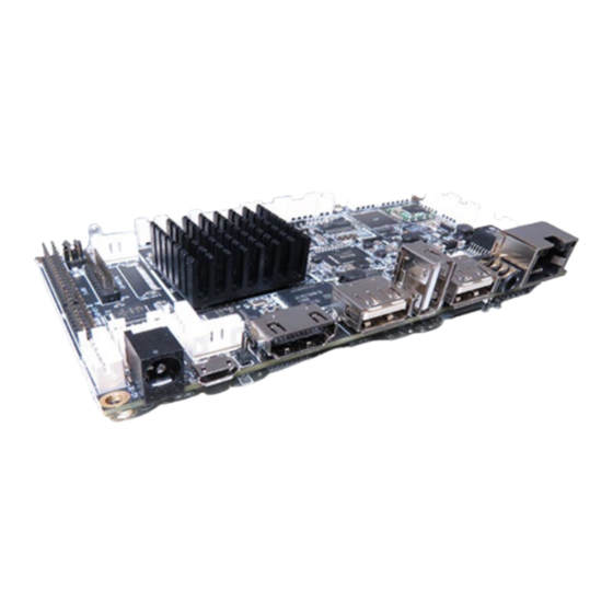
QDS-6100/6200 - User Guide, Rev. 1.0 4.2. Connector Panel Side (Rear) Figure 2: Connector Panel Side (Rear) Table 8: Connector Panel Side Connector List (Rear) Item Designation Description See Chapter 12 V DC Jack HDMI 2.0 Connector 10 / 100 LAN RJ45 Connector Line-out Audio Jack USB 2.0 Type A Connector USB OTG Micro-USB Connector... -
Page 22: Connector Panel Side (Front)
QDS-6100/6200 - User Guide, Rev. 1.0 4.3. Connector Panel Side (Front) Figure 3: Connector Panel Side (Front) Table 9: Connector Panel Side Connector List (Front) Item Designation Description RECOVER Reset Button Power LED Standby Button www.kontron.com // 22... -
Page 23: 5/ Connector Definitions
QDS-6100/6200 - User Guide, Rev. 1.0 5/ Connector Definitions The following defined terms are used within this user guide to give more information concerning the pin assignment and to describe the connector's signals. Defined Term Description Shows the pin numbers in the connector Signal The abbreviated name of the signal at the current pin The notation "XX#"... -
Page 24: 6/ I/O-Area Connectors
QDS-6100/6200 - User Guide, Rev. 1.0 6/ I/O-Area Connectors 6.1. Power Connector The QDS-6100/6200 has a DC jack on the external I/O connector panel. It must be used to supply the board with +12 VDC (±5 %). Figure 4: DC Jack Table 10: Pin Assignment DC Jack Signal Description... -
Page 25: Hdmi Connector
QDS-6100/6200 - User Guide, Rev. 1.0 6.2. HDMI Connector The HDMI connector is based on standard HDMI type A and compliant with HDMI 2.0. Figure 5: HDMI Connector Table 11: Pin Assignment HDMI Connector Signal Description Note TMDS Data2+ HDMI Lane 2 differential pair (+) Ground TMDS Data2- - HDMI Lane 2 differential pair (-) -
Page 26: Ethernet Connector
QDS-6100/6200 - User Guide, Rev. 1.0 6.3. Ethernet Connector The QDS-6100/6200 supports one channel of 10/100 Mbit Ethernet. Figure 6: Ethernet Connector LED status: LED status: Off - Link is down Green - 100 Mbit/s link established Flashing Green - Link is up and active Off - 10 Mbit/s link established Steady Green - Link is up, no activity 8 7 6 5 4 3 2 1... -
Page 27: Usb Connectors (I/O Area)
QDS-6100/6200 - User Guide, Rev. 1.0 6.4. USB Connectors (I/O Area) The external I/O connector panel supports three USB 2.0 connectors and one USB 2.0 OTG connector. USB 2.0 OTG ports can be configured to operate in host mode or device mode via the Jumper OTG based on the desired functionality. -
Page 28: Audio Phone Jack
QDS-6100/6200 - User Guide, Rev. 1.0 6.5. Audio Phone Jack The external I/O connector panel supports one 3.5 mm single-port audio phone jack for headset. The audio output signals are shared with those of the speaker connector. Figure 9: Audio Phone Jack Table 15: Pin Assignment Audio Phone Jack Signal Description... -
Page 29: Micro Sd Card Cage
QDS-6100/6200 - User Guide, Rev. 1.0 6.6. Micro SD Card Cage The external I/O connector panel supports one micro SD card cage for data logging and file storage. Figure 10: Micro SD Card Cage Table 16: Pin Assignment Micro SD Card Cage Signal Description Note... -
Page 30: 7/ Internal Connectors
QDS-6100/6200 - User Guide, Rev. 1.0 7/ Internal Connectors 7.1. Power Connector Power connector must be used to supply the board with +12 VDC (±5 %). 7.1.1. Power Input Wafer (DC) The 1x4-pin 2.0 mm pitch power input wafer provides +12 V DC to the board. Figure 11: Power Input Wafer (DC) Table 17: Pin Assignment (DC) Signal... -
Page 31: Usb Connectors (Internal) (3-Usb)
QDS-6100/6200 - User Guide, Rev. 1.0 7.2. USB Connectors (Internal) (3-USB) The QDS-6100/6200 has one 2x6-pin 2.0 mm pitch USB port pin header which supports three USB 2.0 ports. Figure 13: USB 2.0 Pin Header (3-USB) Table 19: Pin Assignment (3-USB) Signal Description Note... -
Page 32: Microphone Input Wafer (Mic)
QDS-6100/6200 - User Guide, Rev. 1.0 7.4. Microphone Input Wafer (MIC) The microphone input wafer provides microphone (Mic-In) signals through the 2-pin 2.0 mm pitch wafer MIC. Figure 15: Microphone Input Wafer (MIC) Table 21: Pin Assignment (MIC) Signal Description Note MIC+ Microphone input signal (+) -
Page 33: Lvds Panel Connector (2-Lvds)
QDS-6100/6200 - User Guide, Rev. 1.0 7.6. LVDS Panel Connector (2-LVDS) The 30-pole 2.0 mm pitch connector provides 6/8-bit, 1/2-channel LVDS panel connection. Figure 17: LVDS Panel Connector (2-LVDS) Table 24: Pin Assignment (2-LVDS) Signal Description Note VDD* +3.3 V / +5 V / +12 V panel power supply VDD* +3.3 V / +5 V / +12 V panel power supply VDD*... -
Page 34: Panel Backlight Power Output Wafer (Backlight)
QDS-6100/6200 - User Guide, Rev. 1.0 Signal Description Note 1CKP LVDS Channel 1 clock differential pair (+) LVDS Channel 1 Data 3 differential pair (-) LVDS Channel 1 Data 3 differential pair (+) * Panel Power can be selected by Jumper 12V 5V 3.3V. 7.7. -
Page 35: Gpio Wafer (Io0)
QDS-6100/6200 - User Guide, Rev. 1.0 7.8. GPIO Wafer (IO0) The 8-pin 2.0 mm pitch wafer GPIO supports 6-bit general purpose input / output signals to provide powering-on function of the connected devices. Figure 19: GPIO Wafer (IO0) Table 26: Pin Assignment (IO0) Signal Description Note... -
Page 36: Touch Panel Wafer (Tp)
QDS-6100/6200 - User Guide, Rev. 1.0 7.10. Touch Panel Wafer (TP) The 6-pin 2.0 mm pitch touch panel wafer TP supports touch panel control. Figure 21: Touch Panel Wafer (TP) Table 28: Pin Assignment (TP) Signal Description Note 3.3V 3.3 V power supply TP-INT Touch panel interrupt line TP-RST... -
Page 37: Wan Data Wafer (Wan)
QDS-6100/6200 - User Guide, Rev. 1.0 7.12. WAN Data Wafer (WAN) The 4-pin 2.0 mm pitch WAN data wafer is intended to relocate Ethernet connector (Figure 2, pos. 3) to an appropriate location on the chassis. It supports 10 Mbyte only. Figure 23: WAN Data Wafer (WAN) Table 30: Pin Assignment (WAN) Signal... -
Page 38: Switches And Jumpers
QDS-6100/6200 - User Guide, Rev. 1.0 7.13. Switches and Jumpers The product has several jumpers which must be properly configured to ensure correct operation. Figure 24: Jumper Connector For a three-pin jumper (see Figure 24), the jumper setting is designated ‘‘1-2’’ when the jumper connects pins 1 and 2. The jumper setting is designated ‘‘2-3’’... -
Page 39: Otg Control (Otg)
QDS-6100/6200 - User Guide, Rev. 1.0 7.13.2. OTG Control (OTG) The 2-pin 2.0 mm pitch "OTG Control" jumper OTG can be used to select mode in which the USB OTG connector operates. Figure 26: OTG Control (OTG) Table 32: Pin Assignment OTG Control (OTG) Jumper 1 Position Description Pin 1-2... -
Page 40: About Kontron
QDS-6100/6200 - - User Guide, Rev. 1.0 About Kontron Kontron is a global leader in Embedded Computing Technology (ECT). As a part of technology group S&T, Kontron offers a combined portfolio of secure hardware, middleware and services for Internet of Things (IoT) and Industry 4.0 applications.
Need help?
Do you have a question about the Kontron QDS-6100 and is the answer not in the manual?
Questions and answers