Table of Contents
Advertisement
Quick Links
Advertisement
Table of Contents

Subscribe to Our Youtube Channel
Related Manuals for S&T kontron pITX-iMX8M


Summary of Contents for S&T kontron pITX-iMX8M
- Page 1 USER GUIDE pITX-iMX8M User Guide Rev. 1.4 Doc-ID: 1064-7940...
- Page 2 pITX-iMX8M – User Guide Rev. 1.4 This page has been intentionally left blank...
- Page 3 pITX-iMX8M – User Guide Rev. 1.4 PITX-IMX8M – USER GUIDE Disclaimer Kontron would like to point out that the information contained in this manual may be subject to alteration, particularly as a result of the constant upgrading of Kontron products. This document does not entail any guarantee on the part of Kontron with respect to technical processes described in the manual or any product characteristics set out in the manual.
- Page 4 pITX-iMX8M – User Guide Rev. 1.4 Intended Use THIS DEVICE AND ASSOCIATED SOFTWARE ARE NOT DESIGNED, MANUFACTURED OR INTENDED FOR USE OR RESALE FOR THE OPERATION OF NUCLEAR FACILITIES, THE NAVIGATION, CONTROL OR COMMUNICATION SYSTEMS FOR AIRCRAFT OR OTHER TRANSPORTATION, AIR TRAFFIC CONTROL, LIFE SUPPORT OR LIFE SUSTAINING APPLICATIONS, WEAPONS SYSTEMS, OR ANY OTHER APPLICATION IN A HAZARDOUS ENVIRONMENT, OR REQUIRING FAIL-SAFE PERFORMANCE, OR IN WHICH THE FAILURE OF PRODUCTS COULD LEAD DIRECTLY TO DEATH, PERSONAL INJURY, OR SEVERE PHYSICAL OR ENVIRONMENTAL DAMAGE (COLLECTIVELY, "HIGH RISK APPLICATIONS").
- Page 5 pITX-iMX8M – User Guide Rev. 1.4 Revision History Revision Brief Description of Changes Date of Issue Author Initial Issue 2021-February-17 Jumper J29 and J18 in Figure 4: Front Side corrected 2021-February-22 Word2016 issues 2021-March-25 Internal audio header (J9) in chapter 6.18 added, new Table 8: Switch 2021-July-05 SW1 and Table 9: Switch SW2Switch SW1/2 LVDS updates in Table 4 and Table 7...
-
Page 6: Symbols
pITX-iMX8M – User Guide Rev. 1.4 Symbols The following symbols may be used in this manual DANGER indicates a hazardous situation which, if not avoided, will result in death or serious injury. WARNING indicates a hazardous situation which, if not avoided, could result in death or serious injury. -
Page 7: For Your Safety
pITX-iMX8M – User Guide Rev. 1.4 For Your Safety Your new Kontron product was developed and tested carefully to provide all features necessary to ensure its compliance with electrical safety requirements. It was also designed for a long fault-free life. However, the life expectancy of your product can be drastically reduced by improper treatment during unpacking and installation. -
Page 8: Lithium Battery Precautions
pITX-iMX8M – User Guide Rev. 1.4 Lithium Battery Precautions If your product is equipped with a lithium battery, take the following precautions when replacing the battery. Danger of explosion if the battery is replaced incorrectly. Replace only with same or equivalent battery type recommended by the manufacturer. ... -
Page 9: Table Of Contents
pITX-iMX8M – User Guide Rev. 1.4 Table of Contents Symbols............................................6 For Your Safety .......................................... 7 High Voltage Safety Instructions ..................................7 Special Handling and Unpacking Instruction ..............................7 Lithium Battery Precautions ....................................8 General Instructions on Usage ................................... 8 Quality and Environmental Management .............................. -
Page 10: List Of Tables
pITX-iMX8M – User Guide Rev. 1.4 6.8. Pigtail Battery Header (J22) ..................................42 6.9. GPIO Connector (internal, J17) .................................. 42 6.10. Jumper LVDS Panel Voltage (J18) ................................43 6.11. Jumper LVDS Backlight Voltage (J29) ..............................43 6.12. Switches .......................................... 44 6.12.1. -
Page 11: List Of Figures
pITX-iMX8M – User Guide Rev. 1.4 Table 5: Environmental Conditions ................................22 Table 6: Power Consumption .................................... 25 Table 7: Jumpers and Connectors ................................... 26 Table 8: Switch SW1 ......................................27 Table 9: Switch SW2 ......................................27 Table 10: Processor Support ..................................... 33 Table 11: Pin Assignment MicroSIM Combo Socket .......................... - Page 12 pITX-iMX8M – User Guide Rev. 1.4 Figure 11: Combo Connector for MicroSD and MicroSIM ........................35 Figure 12: Ethernet Connector RJ-45 Jack with Integrated Magnetic ....................36 Figure 13: USB 2.0/3.0 socket ................................... 37 Figure 14: USB Internal Connector .................................. 39 Figure 15: USB OTG Connector ..................................
-
Page 13: 1/ Introduction
pITX-iMX8M – User Guide Rev. 1.4 1/ Introduction This manual describes the pico-ITX board with five processors from NXP: i.MX8M QuadLite with 1.5 GHz, i.MX8M Dual with 1.3 GHz and 1.5 GHz, i.MX8M Quad with 1.3 GHz and 1.5 GHz. This board will also be denoted pITX-iMX8M within this Users Guide. -
Page 14: 2/ Description
pITX-iMX8M – User Guide Rev. 1.4 2/ Description The board is based on the NXP´s i.MX8M processor with either dual or quad core ARM. It is mechanically compliant to the Pico-ITX (pITX) specification. Board key features are: 32-bit LPDDR4 3200 MT/s memory (up to 4 GB), ... -
Page 15: Configurations
pITX-iMX8M – User Guide Rev. 1.4 2.1. Configurations Kontron offers the pITX-iMX8M in five different configurations. Table 1: Component Main Data Product Number Article Description 44011-0208-13-2 pITX-iMX8M pITX- iMX8M with Dual Core Industrial NXP i.MX8 M Dual Core Cortex®-A53 1.3 GHz with GPU, VPU and HDR10 encoding, industrial temperature range, 2 GByte LPDDR4, 8 GByte eMMC (pSLC), HDMI and LVDS... -
Page 16: Scope Of Delivery
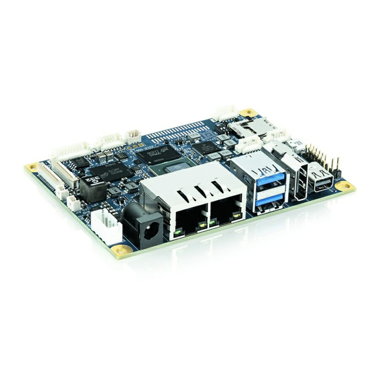
pITX-iMX8M – User Guide Rev. 1.4 Figure 1: pITX-iMX8M Board 2.2. Scope of Delivery Table 2: Scope of Delivery pITX-iMX8M Part Description Module pITX-iMX8M Miscellaneous Quick Installation Guide Table 3: Scope of pITX-iMX8M Kit Part Part No. Description Module pITX-iMX8M Power Supply 1067-1755 12 V Power Supply: SCM PSU AC/DC 60 W 12 V KYCON (0-... -
Page 17: 3/ Installation Procedure
pITX-iMX8M – User Guide Rev. 1.4 3/ Installation procedure 3.1. Installing the Board ESD Sensitive Device! Electrostatic discharge (ESD) can damage equipment and impair electrical circuitry. • Wear ESD-protective clothing and shoes • Wear an ESD-preventive wrist strap attached to a good earth ground •... -
Page 18: Safety Requirements According Iec 62368
pITX-iMX8M – User Guide Rev. 1.4 Connect and turn on PSU Connect PSU to the board by a +12 V DC 2.5mm 4-pin wafer connector or alternatively connect an external +12 V DC power adapter to the rear DC jack. Figure 2: Power Jack (left) and Internal Connector(right) U-Boot Setup Enter the U-Boot setup, more information in Chapter 7/. -
Page 19: Lithium Battery Precautions
pITX-iMX8M – User Guide Rev. 1.4 3.3. Lithium battery precautions Danger of explosion if the lithium battery is incorrectly replaced. • Replace only with the same or equivalent type recommended by the manufacturer • Dispose of used batteries according to the manufacturer’s instructions VORSICHT! Explosionsgefahr bei unsachgemäßem Austausch der Batterie. -
Page 20: 4/ System Specifications
pITX-iMX8M – User Guide Rev. 1.4 4/ System specifications 4.1. Component Main Data The table below summarizes the features of the pITX-iMX8M embedded motherboard. Table 4: Component Main Data Motherboard pITX-iMX8M Form factor Pico-ITX (100 mm by 72 mm by 1.6 mm/Length x Width x Thickness) Mechanical 100 mm x 72 mm x 41 mm (Length x Width x Height) Dimensions with... - Page 21 pITX-iMX8M – User Guide Rev. 1.4 1x USB 2.0 OTG microUSB type A/B 1x Dual-stacked USB3.0 at rear I/O 1x USB2.0 from internal headers 1x USB 3.0 from M.2 B-Key half-size connector Power 1x Locking barrel-type DC Power Jack 1x Internal 4-pin Power connector Display The pITX-IMX8M utilizes the iMX8 M HDMI 2.0a and MIPI-DSI display interfaces.
-
Page 22: Environmental Conditions
pITX-iMX8M – User Guide Rev. 1.4 4.2. Environmental Conditions Table 5: Environmental Conditions Storage IEC 60068-2-1 60068-2-2 Temperature -40°C to +85°C Operating IEC 60068-2-1 60068-2-2 Temperature -40°C to +85°C for Industrial variants (44011-xxxx-13-x) 0°C to +60°C for Commercial variants (44011-xxxx-15-x) Note: The pITX-IMX8M requires a cooling solution for proper operation. -
Page 23: Block Diagram
pITX-iMX8M – User Guide Rev. 1.4 4.3. Block Diagram Figure 3: Block Diagram www.kontron.com // 23... - Page 24 pITX-iMX8M – User Guide Rev. 1.4 www.kontron.com // 24...
-
Page 25: Power Consumption
pITX-iMX8M – User Guide Rev. 1.4 4.4. Power Consumption The pITX-IMX8M power consumption depends on variant used and load profile. Table 6: Power Consumption Power Figures SBC 44011-0208- 44011- 44011-0216- 44011-0416- 44011-0416- 13-2 0408-13-4 15-2 15-4lit 15-4 iMX8 M Industrial + Industrial + Commercial Commercial... -
Page 26: 5/ Jumpers, Switches And Connectors
pITX-iMX8M – User Guide Rev. 1.4 5/ Jumpers, Switches and Connectors 5.1. Hardware Configuration Setting This chapter gives the definitions and shows the positions of jumpers, headers and connectors. All of the configuration jumpers on the board are in the proper position. The default settings shipped from factory are marked with an asterisk (*). -
Page 27: Table 8: Switch Sw1
pITX-iMX8M – User Guide Rev. 1.4 Jumpers Function Remark SPDIF (J10) SPDIF header Header Type: WTB 3-Pin header, 1.25 mm pitch Possible Source: Molex Picoblade™ 53047-0310 Camera (J5, J6) Camera connector Header Type: FCP 24-Pin 0.5 pitch Possible Source: Molex 52559-2452 Battery (J22) Battery pigtail header Header Type: WTB 2-Pin header, 1.25 mm pitch... -
Page 28: Mainboard Placement And I/O Locations
pITX-iMX8M – User Guide Rev. 1.4 5.2. Mainboard Placement and I/O Locations Figure 4: Front Side 10 USB OTG (J28) 11 GPIO connector (J17) SPI/I2C header (J26) 12 Internal DC Power connector (J16) Internal Audio Codec (J9) 13 SPDIF header (J10) LVDS Voltage Jumper (J18) 14 RTC Pigtail Battery Connector (J22) Fan connector (J8) -
Page 29: Figure 5: Interfaces
pITX-iMX8M – User Guide Rev. 1.4 Figure 5: Interfaces 20 DC Power Jack 21 2x Ethernet 22 2x USB 3.0 23 HDMI 24 Mini DP www.kontron.com // 29... -
Page 30: Figure 6: Front View Jumpers/Switches
pITX-iMX8M – User Guide Rev. 1.4 Figure 6: Front View Jumpers/Switches 25 Switch MicroSD (SW2) 26 Switch Boot Select (SW1) 27 External ON/OFF (J24) 28 External Reset (J23) www.kontron.com // 30... -
Page 31: Interfaces Rear Side
pITX-iMX8M – User Guide Rev. 1.4 5.2.1. Interfaces Rear Side Figure 7: Interfaces Rear Side 29 M.2 Socket Key B 30 USB 2.0 P4 www.kontron.com // 31... -
Page 32: Cooler Solutions
pITX-iMX8M – User Guide Rev. 1.4 5.3. Cooler Solutions pITX-iMX8M should only operated with a suitable heat sink. Allow to cool down after operation. 5.3.1. Passive Cooler (1064-7069) Figure 8: Passive Cooler 5.3.2. Active Cooler (1064-8396) Figure 9: Active Cooler www.kontron.com // 32... -
Page 33: 6/ Hardware Specifications
pITX-iMX8M – User Guide Rev. 1.4 6/ Hardware Specifications 6.1. Processor Support The i.MX 8M family of applications processors based on Arm® Cortex®-A53 and Cortex-M4 cores provide audio, voice and video processing for applications that scale from commercial home audio to industrial building automation and mobile computers. -
Page 34: System Memory Support
pITX-iMX8M – User Guide Rev. 1.4 Figure 10: Block Diagram i.MX8M processor (Source: NXP) 6.2. System Memory Support The pITX-iMX8M board supports a 32-bit DRAM interface LPDDR4 memory interface. The integrated memory controller can support memory speeds up to 3200 MT/s. Maximum memory supported is 4 GB. If using 32 Bit OS, less than 4 GB are displayed in the system (Shared Video Memory/PCI resources are subtracted). -
Page 35: Microsd And Microsim (J12)
pITX-iMX8M – User Guide Rev. 1.4 6.3. MicroSD and MicroSIM (J12) The pITX-iMX8M board supports micro SD cards via micro SD/micro SIM combo connector. The micro SD card interface supports the following transfer modes: SD 1-bit SD 4-bit ... -
Page 36: Ethernet Connectors (I/O Area, J4)
pITX-iMX8M – User Guide Rev. 1.4 Function Direction Description SDIO_DAT1 In/Out SDIO_CD# SD card detect G1-G8 Ground 6.4. Ethernet Connectors (I/O area, J4) The pITX-iMX8M supports two channels of 10/100/1000 Mbit/s Ethernet (ETH0 to ETH1). In order to achieve the specified performance of the Ethernet port, Category 5 twisted pair cables must be used with 10/100 MByte/s and Category 5E, 6 or 6E with 1 Gbit/s LAN networks. -
Page 37: Eth0 Leds
pITX-iMX8M – User Guide Rev. 1.4 6.4.1. ETH0 LEDs Table 13: ETH0 LED Signal Description Left RJ45 LEDs Function Green Off = no receive or transmit activities On = receive or transmit activity Yellow Off = no link, 10/100Base-T Link On = 1000Base-T Link 6.4.2. -
Page 38: Table 16: Signal Description
pITX-iMX8M – User Guide Rev. 1.4 Connector Pin Direction Description GND_BOT GROUND Ground USB_BOT_SSRX- INPUT USB3 HUB P2 differential USB 3.0 receive data pairs. USB_BOT_SSRX+ INPUT GND_DRAIN_BOT GROUND Ground USB_BOT_SSTX- OUTPUT USB3 HUB P2 differential USB 3.0 transmit data pairs. USB_BOT_SSTX+ OUTPUT VBUS_TOP... -
Page 39: Usb Internal (J2)
pITX-iMX8M – User Guide Rev. 1.4 6.5.2. USB internal (J2) Figure 14: USB Internal Connector Table 17: USB Internal Connection Function Direction Description Ground USB3_P4_D+ In/Out USB3_P4_D- In/Out V_5V0_USB Power VBUS +5.0V power distribution 500 mA max 6.5.3. USB OTG (J28) Figure 15: USB OTG Connector Table 18: USB OTG Connection Function... -
Page 40: Fan Connector (Internal, J8)
pITX-iMX8M – User Guide Rev. 1.4 6.6. Fan Connector (internal, J8) The fan can be used to actively cool the heatsink mounted on the board. The fan rotation speed can be monitored and the fan speed controlled by the temperature of the PCB (near SoC). Figure 16: 3-pin Fan Connector Table 19: Fan Header Mapping Function... -
Page 41: Dc Power Jack Connector (12 Vin Ext., J15)
pITX-iMX8M – User Guide Rev. 1.4 6.7.1. DC Power Jack Connector (12 Vin Ext., J15) The pITX-iMX8M operates with a 12 V DC +/- 10% power supply. Figure 17: Power Jack Connector Table 21: Power Jack Connector Function Direction VIN 12VDC RTN_12V Ground RTN_12V... -
Page 42: Pigtail Battery Header (J22)
pITX-iMX8M – User Guide Rev. 1.4 6.8. Pigtail Battery Header (J22) The 2-pin header has a 1.25 mm pitch. Figure 19: Pigtail Battery Header Table 23: Pin Assignment Signal V_BAT 6.9. GPIO Connector (internal, J17) Figure 20: GPIO Connector Table 24: GPIO Connector Function Direction Description... -
Page 43: Jumper Lvds Panel Voltage (J18)
pITX-iMX8M – User Guide Rev. 1.4 6.10. Jumper LVDS Panel Voltage (J18) Figure 21: LVDS Panel Voltage Table 25: LVDS Panel Voltage Function Direction V_5V_S0 Power V_5V0_3V3_JP Power V_3V3_S0 Power Function: Pin 1-2: 5V LVDS Panel Voltage is 5.0 V Pin 2-3: 3.3V LVDS Panel Voltage (Default) 6.11. -
Page 44: Switches
pITX-iMX8M – User Guide Rev. 1.4 6.12. Switches 6.12.1. Boot Select (SW1) The Boot Select Switch SW 1 determines the iMX8M boot modes. Table 27: Boot Select Switch (SW1) SW1: 2-3 SW1: 1-4 iMX8M SCU iMX8M SCU Description Boot Mode 1 Boot Mode 0 Boot from fuse (default) Serial Downloader... -
Page 45: External Reset (J23)
pITX-iMX8M – User Guide Rev. 1.4 6.13.2. External Reset (J23) Table 31: External Reset Button Function Direction RESET# Ground 6.14. LVDS (Industrial Variant, internal, J11) Figure 23: LVDS Connector (optional) Table 32: LVDS Pin Assignment Function Direction Description V_12V_LVDS_BS Power +12V LVDS Backlight Circuit Supply V_12V_LVDS_BS Power... -
Page 46: Hdmi Connector (J7)
pITX-iMX8M – User Guide Rev. 1.4 Function Direction Description LVDS0_CK+ LVDS channel 0, clock, positive LVDS0_3- LVDS channel 0, lane 3, negative LVDS0_3+ LVDS channel 0, lane 3, positive Ground Ground LVDS1_0- LVDS channel 1, lane 0, negative LVDS1_0+ LVDS channel 1, lane 0, positive LVDS1_1- LVDS channel 1, lane 1, negative LVDS1_1+... -
Page 47: Mini Display Port (J14)
pITX-iMX8M – User Guide Rev. 1.4 Function Direction Description HDMI_D3_+ Ground TMDS Clock Channel HDMI_D3_- HDMI_CEC In/Out HDMI_AUX_- Optional usage as Audio Return Channel HDMI_DDC_SCL HDMI DDC Serial Clock HDMI_DDC_SDA In/Out HDMI DDC Serial Date Ground V_5V0_HDMI Power HDMI_AUX_+/HPD Hot plug detect, optional usage as Audio Return Channel 6.16. -
Page 48: Spdif Internal Audio Header (J10)
pITX-iMX8M – User Guide Rev. 1.4 Function Direction Description DP0 TX2+ DP0 AUX+ In/Out DP0 TX2- DP0 AUX- In/Out Ground DP Power Power Out +3.3V, 0.75A max 6.17. SPDIF Internal Audio Header (J10) Figure 26: SPDIF Internal Header with 3 pins Table 35: Pin Assignment Function Direction... -
Page 49: Internal Audio (J9)
pITX-iMX8M – User Guide Rev. 1.4 6.18. Internal audio (J9) Figure 27: Internal Audio Header with 6 pins Table 36: Pin Assignment Function Line-Out Right Audio GND Line-Out Left Line-In Right Microphone In Line-In Left 6.19. SPI/I2C3 (J26) Table 37: SPI/I2C Pin Assignment Function Direction Description... -
Page 50: Connector (B-Key) (J1)
pITX-iMX8M – User Guide Rev. 1.4 6.20. M.2 Connector (B-Key) (J1) Figure 28: M.2 Connector (B-Key) Table 38: Pin Assignment Signal/Function M.2 Signal M.2 Signal Signal/Function V_3V3_M2, +3.3V S0 M2_CONFIG_3, 3.3V CONFIG_3 filtered Pull-up to 3.3V S0 V_3V3_M2 3.3V (V_3V3_S0) M2_FULL_CARD_ FULL_CARD_POWER POWER_OFF# pulled... - Page 51 pITX-iMX8M – User Guide Rev. 1.4 Signal/Function M.2 Signal M.2 Signal Signal/Function DEVSLP (O) PETp1/USB3.0-Tx+/ USB3_SSTX_M2+ SSIC-TxP I2C2_SCL_1V8 GPIO_0 (I/O)(0/1.8V) I2C2_SDA_1V8 GPIO_1 (I/O)(0/1.8V) PERn0/SATA-B+ PCIE_M2_RX_+ GPIO_2 (I/O)(0/1.8V) PERp0/SATA-B- PCIE_M2_RX_- GPIO_3 (I/O)(0/1.8V) GPIO_4 (I/O)(0/1.8V) PETn0/SATA-A- PCIE_M2_TX_- M2_PERST# IMX8M PERST# (O) (0/3.3V) PETp0/SATA-A+ PCIE_M2_TX_+ GPIO1_IO09...
-
Page 52: Serial Com P1 (J25)
pITX-iMX8M – User Guide Rev. 1.4 6.21. Serial COM P1 (J25) Figure 29: Serial Wafer Socket COM P1 Table 39: Pin Assignment Signal Direction RS232_P1_TXD RS232_P1_RXD Ground 6.22. Serial COM P2 (J3) Figure 30: Serial Wafer Socket COM P2 Table 40: Pin Assignment Signal Direction RS232_P2_TXD... -
Page 53: Serial Com P3 (J19)
pITX-iMX8M – User Guide Rev. 1.4 Table 41: Pin Assignment (assembly option) Signal Direction RS232_P2_TXD RS232_P2_RXD Ground 6.23. Serial COM P3 (J19) Figure 31: Serial Wafer Socket COM P3 Table 42: Pin Assignment RS232 only Signal Direction RS232_P3_TXD RS232_P3_RXD RS232_P3_RTS# RS232_P3_CTS# Ground 6.24. - Page 54 pITX-iMX8M – User Guide Rev. 1.4 Signal Direction CSI1_RX0- CSI1_RX0+ CSI1_CK- CSI1_CK+ CSI1_RX1- CAM_XCLK_1V8_CAM1 CSI1_RX1+ V_1V8_S0_CSI1 Power V_1V5_CAM_CSI1 Power CSI_P1_PWDN_1V8 CSI_P1_RST_1V8# I2C1_SCL_1V8 V_2V8_CAM1_S0 I2C1_SDA_1V8 In/Out Ground www.kontron.com // 54...
-
Page 55: Table 44: Pin Assignment (J6)
pITX-iMX8M – User Guide Rev. 1.4 Table 44: Pin Assignment (J6) Signal Direction V_2V8_CAM2_S0 Power CSI2_RX0- CSI2_RX0+ CSI2_CK- CSI2_CK+ CSI2_RX1- CAM_XCLK_1V8_CAM1 CSI2_RX1+ V_1V8_S0_CSI1 Power V_1V5_CAM_CSI1 Power CSI_P2_PWDN_1V8 CSI_P2_RST_1V8# I2C3_SCL_1V8 V_2V8_CAM2_S0 Power I2C3_SDA_1V8 In/Out Ground www.kontron.com // 55... -
Page 56: Thermal Sensor (U24)
pITX-iMX8M – User Guide Rev. 1.4 6.25. Thermal Sensor (U24) The pITX-IMX8M monitors the PCB ambient temperature between iMX8 M, eMMC and LPDDR4 device with an LM75B temperature sensor. The iMX8 M I2C 1 interface connects to LM75B. The I2C 7-bit address is set to 0x4B. Figure 33: Sensor Location (red circle) pITX-iMX8M should only operated with a suitable heat sink. -
Page 57: 7/ Bootloader Operation
pITX-iMX8M – User Guide Rev. 1.4 7/ Bootloader Operation 7.1. Copyrights and Licensing of U-Boot U-Boot is free Software. It is copyrighted by Wolfgang Denk and many others who contributed code. U-Boot can be redistributed and modified under the terms of version 2 of the GNU General Public (GPL V2) License as published by the Free Software Foundation. -
Page 58: Bootloader Commands
U-Boot 2020.04-00181-gdf4caed7c3 (Dec 09 2020 - 14:52:15 +0100), Build: PITX-IMX8M-R11 CPU: i.MX8MQ rev2.1 1300 MHz (running at 800 MHz) CPU: Industrial temperature grade (-40C to 105C) at 56C Reset cause: POR Model: Kontron pITX-iMX8M DRAM: 4 GiB WDT: Started with servicing (60s timeout) MMC: FSL_SDHC: 0, FSL_SDHC: 1 Loading Environment from MMC... -
Page 59: Kontron Bootloader Command Extensions
pITX-iMX8M – User Guide Rev. 1.4 7.4. Kontron Bootloader Command Extensions Kontron’s implementation of U-Boot includes some enhancements to provide board specific functions. They are not part of standard U-Boot as maintained by DENX. The following table provides a complete listing of all Kontron command extensions on the PITX-iMX8M. -
Page 60: Bootloader Environment Update
pITX-iMX8M – User Guide Rev. 1.4 "editenv", "printenv" "saveenv". U-Boot standard environment variables are set up for the PITX-iMX8M module. Table 46: Standard Environment Variables Variable Value Description baudrate 115200 Serial line baudrate bootcmd run distro_bootcmd Try booting (in this order) from devices defined in the boot_targets variable: mmc0 (eMMC), mmc1 (SD card), usb0, dhcp bootdelay... -
Page 61: Kontron Bootloader Environment Extensions
pITX-iMX8M – User Guide Rev. 1.4 7.7. Kontron Bootloader Environment Extensions To support PITX-iMX8M board properly, Kontron adds some environment variables to the standard set of variables provided by mainline U-Boot. These variables are shown below. Table 47: Bootloader Environment Extensions Variable Value Description... -
Page 62: Sd Card And Emmc Devices
pITX-iMX8M – User Guide Rev. 1.4 7.8.2. SD Card and eMMC Devices eMMC and SD card are accessed using the "mmc" command Example: Load 256 blocks from eMMC => mmc dev 1 => mmc read ${loadaddr} 0 100 7.8.3. USB Storage Device USB storage devices are accessed using "usb"... -
Page 63: 8/ Technical Support
pITX-iMX8M – User Guide Rev. 1.4 8/ Technical Support For technical support contact our Support department: E-mail: support@kontron.com Phone: +49-821-4086-888 Make sure you have the following information available when you call: Product ID Number (PN), Serial Number (SN) The serial number can be found on the Type Label, located on the product’s rear side. - Page 64 pITX-iMX8M – User Guide Rev. 1.4 Fax: +49 (0) 821 4086 111 Email: service@kontron.com The goods for repair must be packed properly for shipping, considering shock and ESD protection. Goods returned to Kontron Europe GmbH in non-proper packaging will be considered as customer caused faults and cannot be accepted as warranty repairs.
-
Page 65: About Kontron - Member Of The S&T Group
About Kontron – Member of the S&T Group Kontron is a global leader in Embedded Computing Technology (ECT). As a part of technology group S&T, Kontron offers a combined portfolio of secure hardware, middleware and services for Internet of Things (IoT) and Industry 4.0 applications.
Need help?
Do you have a question about the kontron pITX-iMX8M and is the answer not in the manual?
Questions and answers