
Related Manuals for Recom RCM-4-TP-D

Summary of Contents for Recom RCM-4-TP-D
- Page 1 Grid-connected PV Inverter T h r e e P h a s e D u a l M P PT User Manual RCM-4-TP-D/RCM-5-TP-D/RCM-6-TP-D/RCM-8-TP-D/ RCM-10-TP-D/RCM-12-TP-D/RCM-15-TP-D/ RCM-17-TP-D/ RCM-20-TP/ RCM-25-TP-D RECOM TECHNOLOGIES...
-
Page 3: Table Of Contents
CONTENTS 1. Preface ........................5 1.1 Overview ....................... 5 1.2 Target Groups ....................5 2. Safety Instructions .................... 5 2.1 Safety Notes ....................5 2.2 Statement ..................... 5 2.3 Important Safety Matters ................6 2.4 Symbols Explanation ................... 7 3. Product Introduction .................. - Page 4 The products, services or features you purchase are subject to the commercial contracts and terms of RECOM TECHNOLOGIES. All or part of the products, services or features described in this document may not be within your purchasing or using scope.
-
Page 5: Preface
1. Preface 1.1 Overview This manual is an integral part of RECOM RCM 4~25-TP series three-phase inverters (hereinafter referred to as the inverters). It mainly introduces the assembly, installation, electrical connection, debugging, maintenance and troubleshooting of the products. Before installing and using inverters, please read this manual carefully, understand the safety information and be familiar with the functions and characteristics of inverters. -
Page 6: Important Safety Matters
2.2.2 Damages caused by incorrect storage, installation or use. 2.2.3 Damages caused by installation and use of equipment by non-professionals or untrained personnel. 2.2.4 Damages caused by failure to comply with the instructions and safety warnings in the products and documents. 2.2.5 Damages caused by running in an environment that doesn't meet the requirements which stated in the documents. -
Page 7: Symbols Explanation
2.4 Symbols Explanation This chapter mainly elaborates the symbols displayed on the inverter, nameplate and packing box. 2.4.1 Symbols on the Inverter Symbol Description Inverter status indicator. Inverter running indicator. Grounding symbol, the inverter casing needs to be properly grounded. 2.4.2 Symbol on the Inverter nameplate Symbol Description... - Page 8 2.4.3 Symbol on the Packing box Symbol Description Handle with care. This side up. Keep dry. Stacked layers.
-
Page 9: Product Introduction
3.1.3 Applicable grid type The applicable grid types for the RECOM RCM 4~25-TP-D series are TN-S, TN-C, TN-C-S, IT and TT. When applied to the TT grid, the voltage of N to PE should be less than 30V. See Figure 3-1 for details: 3.1.4 Storage conditions... -
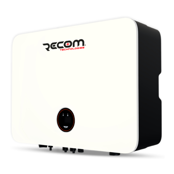
Page 10: Appearance Introduction
3.2 Appearance Introduction 3.2.1 Inverter front view, as shown in Figure 3-2: 550mm Logo Display Figure 3-2 Front view 3.2.2 Inverter side view, as shown in Figure 3-3: 175mm Name Plate Figure 3-3 Side view... - Page 11 3.2.3 Inverter bottom view, as shown in Figure 3-4: DC Switch (Optional) Com2 Port Back Rail (Optional) DC Input Terminal Com1 Port Figure 3-4 Bottom view 3.2.4 Inverter back view, as shown in Figure 3-5: Back Rail Vent Valve Figure 3-5 Inverter back view...
-
Page 12: Display Interface
3.3 Display Interface Figure 3-6 Display interface Item Indicator Status Description No input voltage detected or input voltage is too low. Slow flashing Inverter powered on, waiting for the grid connection. Power Indicator Quick flashing Inverter detected grid power and entered self-test status. Always on Normal, grid-connected and power generated. -
Page 13: Packing List
DRED version only (This connector already pre-installed inside the inverter). 4. Product Installation 4.1 Selection of Installation Location The RECOM RCM 4~25-TP-D series is designed with IP65 protection for indoor and outdoor installations. When selecting an inverter installation location, the following factors should be considered: 1) The wall on which the inverter is mounted must be strong and can withstand the weight of the inverter for a long time. - Page 14 Figure 4-1 Recommended installation Warning Do not put flammable and explosive articles around the inverter. 4.1.2 The requirements for inverter installation spacing are shown in Figure 4-2: 300mm 300mm 300mm Figure 4-2 Recommended installation space 4.1.3 The installation angle of the inverter is recommended as shown in Figure 4-3: Max 30°...
-
Page 15: Mounting The Inverter
4.2 Mounting the Inverter 4.2.1 Wall bracket installation Dimensions of wall bracket, see Figure 4-4: 300mm 150mm 150mm 150mm Figure 4-4 Dimensions of wall bracket 1) Use the wall bracket as the template to mark the position of 5 holes on the wall. See Figure 4-5 for details: Figure 4-5 Mark the hole position... - Page 16 2) Use an electrical driller with 10mm diameter bit to drill 5 holes on the wall and make sure hole depth is 80mm. Before drilling, make sure to avoid the buried water tube and electric wires Warning in the wall to avoid danger. 3) Insert the expansion tubes into the holes and tighten them, then fix the bracket onto the wall with expansion screws by using a cross screwdriver, as shown in Figure 4-6: Figure 4-6 Fix the wall bracket...
-
Page 17: Electrical Connection
Do not use other brands or other types of PV terminals other than the PV Attention terminal in the accessory package. RECOM TECHNOLOGIES has the right to refuse all damages caused by the mixed-use of terminals. Moisture and dust can damage the inverter, ensure the cable gland is securely Attention tightened during installation. - Page 18 3) Disassemble the connector in the accessory bag, as shown in Figure 4-9: Figure 4-9 4) Insert the DC cable through the DC connector nut into the metal terminal and press the terminal with a professional crimping plier (pull back the cable with some power to check if it’s tight enough), as shown in Figure 4-10: Cr i mpi n g P l i e r Figure 4-10...
- Page 19 Figure 4-12 4.3.2 Connection of AC output The RECOM RCM 4~25-TP-D series three phase inverter applies to the three-phase power grid with a voltage of 230/400V and a frequency of 50/60Hz. The recommended cable and AC breaker for the RECOM RCM 4-25TP-D series three phase...
- Page 20 2) According to the table above, select an appropriate copper cable, peel the insulation sleeve of AC cable off for 50mm, and peel off the end of 3L /PE / N wires for 8mm, as shown in Figure 4-14: Wire Diameter:13-18mm St r i p Len gt h: 8mm 50mm Figure 4-14...
- Page 21 5) Connect the AC connector to the inverter AC terminal, and rotate the AC connector buckle clockwise until its tight enough. As shown in figure 4-17: Figure 4-17 Connect the AC connector 4.3.3 External ground connection Connect the inverter and ground bar through PE wire to achieve the purpose of grounding protection.
-
Page 22: Monitoring Device Installation
Figure 4-18 Grounding terminal connection 4.4 Monitoring Device Installation RECOM RCM 4~25-TP-D series three phase inverter supports WiFi, GPRS and RS485 communication, you can choose according to your specific needs. Plug the WiFi or GPRS module into the COM1 port in the bottom of inverter by following the direction the side with indicator is up (as shown in Figure 4-19). -
Page 23: Rs485/Dred Connection
1.The GPRS version module does not need to be configured. 2.The WiFi version module needs to be configured to the router for the first Note installation, and if the router name or password changed, you need to configure it again. For details, please refer to the [QUICK INSTALLATION GUIDE] which attached in the accessory bag. - Page 24 (DRM). This function is for inverter that comply Port 3 with AS/NZS4777.2:2015 standard. 3.RECOM inverter is fully complied with all DRM. DRM3/7 The 6pin connector is used for DRM connection. 4.Support DRM command: DRM0, DRM5, DRM6, DRM7, DRM8.
- Page 25 4.5.3 Anti-reverse or power limit solution Anti-reverse or power limit solution, wiring instructions and configuration, please contact RECOM TECHNOLOGIES after-sales at info@recom-solar.com. 4.5.4 Connection steps: 1) Remove the CT/DRED plate in the bottom of the inverter with a cross screwdriver.
-
Page 26: System Layout Of Units Without Integrated Dc Switch
Insulator ring 20-25mm Port 1 Port 2 20-25mm Port 3 Screw cap Metal plate Sealing ring 3/6pin connector Figure 4-22 Figure 4-23 4.6 System Layout of Units without Integrated DC Switch Local standards or codes may require that PV systems are fitted with an external DC switch on the DC side. -
Page 27: Start And Stop
Inverter Grid DC Switch DC INPUT AC OUTPUT AC Breaker To grounding electrode Figure 4-24 5. Start and Stop 5.1 Start Inverter When starting the inverter, follow these steps: 1) Turn on the AC breaker first. 2) Turn on the DC switch in the bottom. If the PV string voltage higher than the inverter start-up voltage, the inverter will start. -
Page 28: General Operation
6. General Operation 6.1 Display Operation When the inverter is turned on, the following interfaces will be displayed on the OLED display, and you can check the information and modify the parameters of the inverter by short or long pressing the button. Please refer to the following display operation flow for details: Main Window Firmware Updating... -
Page 29: Auto-Test
6.2 Auto-Test This function is disabled by default, and only will be functional in the safety code of Italy. Short press the button several times until “Auto Test CEI 0-21” displays on the screen, press and hold the button 3 seconds to activate “Auto Test”. After the auto test finished, short press the button several times until the screen displays “Auto Test Record”, and hold the button 3 seconds to check the test result. -
Page 30: Troubleshooting
7. Troubleshooting 7.1 Fault Messages RECOM RCM 4~25-TP-D series three-phase inverter is designed in accordance with grid operation standard, and conform to the requirements of the safety and EMC. The inverter had passed a series of rigorous tests to ensure it runs sustainably and reliably before shipment. -
Page 31: Maintenance
Attention arbitrarily replace any internal components. For any maintenance need, please contact RECOM TECHNOLOGIES. Otherwise, RECOM TECHNOLOGIES shall not be held liable for any damage caused. Servicing of the device in accordance with the manual should never be Note undertaken in the absence of proper tools, test equipment or the latest revision of the manual which has been clearly and thoroughly understood. -
Page 32: Technical Parameters
8. Technical Parameters RCM- RCM- RCM- RCM- RCM- RCM- RCM- RCM- RCM- RCM- Model 4-TP-D 5-TP-D 6-TP-D 8-TP-D 10-TP-D 12-TP-D 15-TP-D 17-TP-D 20-TP-D 25-TP-D DC Input Start-up Voltage (V) Max. DC Input Voltage (V) 1,100 1,100 1,100 1,100 1,100 1,100 1,100 1,100 1,100... - Page 33 RCM- RCM- RCM- RCM- RCM- RCM- RCM- RCM- RCM- RCM- Model 4-TP-D 5-TP-D 6-TP-D 8-TP-D 10-TP-D 12-TP-D 15-TP-D 17-TP-D 20-TP-D 25-TP-D Efficiency Max. Efficiency 98.1% 98.1% 98.3% 98.3% 98.6% 98.6% 98.6% 98.6% 98.6% 98.6% European Efficiency 97.9% 97.9% 98.0% 98.0% 98.2% 98.2% 98.2%...
- Page 34 www.recom-solar.com...
Need help?
Do you have a question about the RCM-4-TP-D and is the answer not in the manual?
Questions and answers