
Subscribe to Our Youtube Channel
Related Manuals for Yamaha TRACER MTT850D


Summary of Contents for Yamaha TRACER MTT850D
- Page 1 Read this manual carefully before operating this vehicle. OWNER’S MANUAL MTT850D B1J-28199-E2...
- Page 2 For Europe Declaration of Conformity: Hereby, YAMAHA MOTOR ELECTRONICS Co., Ltd declares that the radio equipment type, IMMOBILIZER, 1RC-00 is in compliance with Directive 2014/53/EU. The full text of the EU declaration of conformity is available at the following internet address: https://global.yamaha-motor.com/eu_doc/...
- Page 3 EAU10103 Welcome to the Yamaha world of motorcycling! As the owner of the MTT850D, you are benefiting from Yamaha’s vast experience and newest technology regarding the design and manufacture of high-quality products, which have earned Yamaha a reputation for dependability.
- Page 4 Important manual information EAU10134 Particularly important information is distinguished in this manual by the following notations: This is the safety alert symbol. It is used to alert you to potential personal injury hazards. Obey all safety messages that follow this symbol to avoid possible injury or death.
- Page 5 Important manual information EAU10201 MTT850D OWNER’S MANUAL ©2020 by Yamaha Motor Co., Ltd. 1st edition, August 2019 All rights reserved. Any reprinting or unauthorized use without the written permission of Yamaha Motor Co., Ltd. is expressly prohibited. Printed in Japan.
-
Page 6: Table Of Contents
Table of contents Safety information......1-1 Storage compartment ....3-38 General maintenance and Windshield ........3-38 lubrication chart ......6-5 Description ........2-1 Adjusting the headlight beams ..3-38 Removing and installing the Left view ......... 2-1 Handlebar position .......3-39 panel..........6-9 Right view........2-2 Adjusting the front fork ....3-39 Checking the spark plugs..... - Page 7 Table of contents Checking and lubricating the Diagnostic connector...... 9-2 throttle grip and cable....6-26 Vehicle data recording ....9-2 Checking and lubricating the brake and shift pedals ....6-26 Index ..........10-1 Checking and lubricating the brake and clutch levers....6-27 Checking and lubricating the centerstand and sidestand ..6-27 Lubricating the swingarm pivots ...6-28 Checking the front fork....6-28...
-
Page 8: Safety Information
Safety information Never operate a motorcycle with- pears to be very effective in reduc- EAU1028C out proper training or instruction. ing the chance of this type of Take a training course. Beginners accident. Be a Responsible Owner should receive training from a cer- Therefore: As the vehicle’s owner, you are re- tified instructor. - Page 9 Safety information Many accidents involve inexperi- • Always signal before turning or Protective Apparel enced operators. In fact, many op- changing lanes. Make sure that The majority of fatalities from motorcy- erators who have been involved in other motorists can see you. cle accidents are the result of head in- ...
- Page 10 Safety information Do not run engine outdoors where Avoid Carbon Monoxide Poisoning When loading within this weight limit, All engine exhaust contains carbon engine exhaust can be drawn into keep the following in mind: Cargo and accessory weight monoxide, a deadly gas.
- Page 11 Yamaha accessories, which are avail- performed to your vehicle that change lightweight as possible and able only from a Yamaha dealer, have any of the vehicle’s design or operation should be kept to a minimum. been designed, tested, and approved characteristics can put you and others •...
- Page 12 Safety information Remove all loose items from the operator and may limit control ability, therefore, such accesso- motorcycle. Check that the fuel cock (if ries are not recommended. Use caution when adding electri- equipped) is in the off position and cal accessories.
-
Page 13: Description
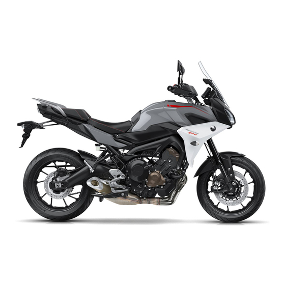
Description EAU10411 Left view 1. Windshield (page 3-38) 9. Shift pedal (page 3-26) 2. Battery (page 6-30) 10.Engine oil drain bolt (page 6-11) 3. Fuses (page 6-31) 11.Engine oil filter cartridge (page 6-11) 4. Storage compartment (page 3-38) 5. Tool kit (page 6-2) 6. -
Page 14: Right View
Description EAU10421 Right view 3,4,5 1. Rear brake fluid reservoir (page 6-21) 9. Engine oil level check window (page 6-11) 2. Fuel tank cap (page 3-30) 10.Engine oil filler cap (page 6-11) 3. Rebound damping force adjuster (page 3-39) 11.Brake pedal (page 3-27) 4. -
Page 15: Controls And Instruments
Description EAU10431 Controls and instruments 1. Clutch lever (page 3-25) 9. Grip warmer (page 3-14) 2. Left handlebar switches (page 3-3) 10.Main switch/steering lock (page 3-2) 3. Auxiliary DC jack (page 3-43) 4. Instrument panel (page 3-5, 3-11) 5. Front brake fluid reservoir (page 6-21) 6. -
Page 16: Instrument And Control Functions
When necessary, take the tire immobilizer system must be re- vehicle along with all three keys to a placed. Therefore, handle the keys Yamaha dealer to have them re-regis- carefully. Do not submerse in water. tered. Do not expose to high tempera- Do not use the key with the red bow for driving. -
Page 17: Main Switch/Steering Lock
Instrument and control functions EAU10474 EAU84031 EAU1068B Main switch/steering lock LOCK All electrical circuits are supplied with The steering is locked and all electrical power and the vehicle lights are turned systems are off. The key can be re- on. The engine can be started. The key moved. -
Page 18: Handlebar Switches
Instrument and control functions ECA20760 EAU66055 Handlebar switches NOTICE If the steering will not lock, try turning Using the hazard or turn signal lights Left the handlebars back to the right slight- for an extended length of time may cause the battery to discharge. To unlock the steering 1. - Page 19 Instrument and control functions Right EAU66040 EAU66010 Turn signal switch “ ” Hazard switch “ ” To signal a right-hand turn, push this With the key in the “ON” or “ ” posi- switch to “ ”. To signal a left-hand tion, use this switch to turn on the haz- turn, push this switch to “...
-
Page 20: Indicator Lights And Warning Lights
Instrument and control functions warmer display is selected or the EAU84271 EAU4939G Wheel switch “ ” Indicator lights and warning fuel tripmeter (F-TRIP) is dis- When the display is set to the main lights played. screen, use the wheel switch to scroll ... - Page 21 Yamaha dealer check the vehi- verts to conventional braking. If ei- cle. ther of the above occurs, or if the...
- Page 22 If the indicator light does not come on vehicle and all 3 keys to a Yamaha Yamaha dealer check vehicle. initially when the key is turned to “ON”,...
-
Page 23: Cruise Control System
Improper use of the cruise con- confirming the proper oil level, trol system may result in loss of have a Yamaha dealer check control, which could lead to an the vehicle. Do not continue to accident. Do not activate the... - Page 24 Instrument and control functions Activating and setting the cruise You can also manually increase your control system traveling speed using the throttle. After 1. Push the cruise control power you have accelerated, you can set a switch “ ” located on the left new cruising speed by pushing the handlebar.
- Page 25 Instrument and control functions Apply the front or rear brake. When traveling with a set cruising Squeeze the clutch lever. speed, if the cruise control system is Pushing the power switch while the Use the shift pedal. deactivated under the above condi- system is operating will turn the sys- Push the power switch to turn off the...
-
Page 26: Display
Instrument and control functions ing speed. If this occurs, acceler- EAU84301 Display ate to the desired traveling speed 12 : 00 The following items can be found on using the throttle. 1000 r/min the display. When the vehicle is traveling ... - Page 27 If all the fuel meter display segments hicle first powered continue counting after 9999.9 flash repeatedly, have a Yamaha deal- tachometer will sweep across the r/min has been reached. er check the related circuits. range and then return to zero.
- Page 28 “1”, “2” or “OFF”. (See page and the quick shift system will be un- 3. While the item is flashing, press 3-28.) available. Have a Yamaha dealer check and hold the wheel switch for one the vehicle. second. 3-13...
- Page 29 Instrument and control functions Air temperature display 2. Short push the wheel switch, and Warning icons This display indicates the air tempera- then rotate the wheel switch up or ture from –9 °C to 50 °C in 1 °C incre- down to change the setting while ments.
-
Page 30: Menu Screen
Return all settings to fac- warning icon will flash repeatedly. Maintenance Maintenance All Reset tory default settings. Have a Yamaha dealer check the vehi- Unit cle. Wallpaper MENU access and operation ECA26400 The following wheel switch operations Shift Indicator... - Page 31 Instrument and control functions 12 : 00 MENU The MENU screen can be ac- 12 : 00 Maintenance km/h km/h Maintenance Maintenance cessed by long pushing the wheel 0 km Unit switch, except when the grip INTERVAL 1 123456 km Wallpaper warmer display is selected or the INTERVAL 2...
- Page 32 Instrument and control functions 3. Select the units you want to use. 12 : 00 MENU km/h 12 : 00 Maintenance Unit km/h Unit Unit km or mile Wallpaper Shift Indicator km/L or L/100km km/L Display Setting Brightness 1. Photo sensor 2.
- Page 33 Instrument and control functions “Shift indicator” The shift indicator module contains the 12 : 00 12 : 00 Wallpaper Shift Indicator km/h km/h following items. Shift IND Setting Display Description NIGHT Shift IND Brightness Set the shift indicator pat- Tach IND Setting tern to “ON”, “Flash”, or Shift IND “OFF”...
- Page 34 Instrument and control functions 12 : 00 12 : 00 Shift Indicator Shift Indicator 12 : 00 Shift Indicator km/h km/h km/h 1000 r/min 1000 r/min Shift IND Setting Shift IND Setting Shift IND Setting Shift IND Brightness IND Mode IND Mode Tach IND Setting IND Start...
- Page 35 Instrument and control functions black or white (depending on wallpa- 3. Select ON to turn the tachometer up to the “Tach IND 2nd” setting per settings). When turned on, the mid color display mode on (or select value (or the red zone), will be dis- and mid-to-high r/min zones can be OFF to turn this function off).
- Page 36 Instrument and control functions 7. Set the orange color starting r/min “Peak Rev IND Setting” “Display Setting” by rotating and then short pushing This module allows you to turn the rev- This module allows you to set how the the wheel switch. All r/min above olution peak hold indicator on or off.
- Page 37 Instrument and control functions 12 : 00 MENU 12 : 00 12 : 00 Display Setting Display Setting km/h km/h km/h Maintenance DISPLAY-1 DISPLAY-1 Unit 1 - 1 A.TEMP 1 - 1 A.TEMP Wallpaper 1 - 2 C.TEMP 1 - 2 C.TEMP Shift Indicator Display Setting...
- Page 38 Instrument and control functions To set the grip warmer temperature levels 12 : 00 MENU 12 : 00 Grip Warmer Setting km/h km/h 1. From the MENU screen, select Maintenance Level 1 “Grip Warmer Setting”. Unit MIDDLE Level 5 Wallpaper HIGH Level 10 12 : 00...
- Page 39 Instrument and control functions 12 : 00 12 : 00 12 : 00 MENU Clock Clock km/h km/h km/h Shift Indicator Display Setting Brightness Grip Warmer Setting Clock Clock All Reset 2. When “Clock” is selected, the 4. The minutes figure will become 6.
-
Page 40: D-Mode (Drive Mode)
Instrument and control functions This mode allows the rider to enjoy EAU84420 EAU12822 D-mode (drive mode) Clutch lever smooth and sporty drivability from the D-mode is an electronically controlled low-speed range to the high-speed engine performance system with three range. mode selections: “STD”, “A”, and “B”. -
Page 41: Shift Pedal
Instrument and control functions EAU84321 EAU84330 EAU26826 Shift pedal Quick shift system Brake lever The quick shift system (QS) allows for The brake lever is located on the right full-throttle, clutch lever-less, electron- side of the handlebar. To apply the ically-assisted upshifts. -
Page 42: Brake Pedal
EAU12944 EAU63040 Brake pedal The ABS performs a self-diagno- The Yamaha ABS (Anti-lock Brake sis test each time the vehicle first System) features a dual electronic con- starts off after the key is turned to trol system, which acts on the front and “ON”... -
Page 43: Traction Control System
Instrument and control functions EAU84342 Traction control system The traction control system (TCS) helps maintain traction when acceler- ating on slippery surfaces, such as un- paved or wet roads. If sensors detect that the rear wheel is starting to slip (uncontrolled spinning), the traction control system assists by regulating engine power as needed until traction... - Page 44 Instrument and control functions Push the TCS switch “ The “ ” indicator light comes on ” to turn ECA16801 NOTICE when traction control has been turned traction control back on (TCS will off. Use only the specified tires. (See return to the previous setting).
-
Page 45: Fuel Tank Cap
Instrument and control functions 4. Have a Yamaha dealer check the EAU13076 Fuel tank cap vehicle and turn off the “ ” warning light. 12:00 1000 r/min km/h 1234.5 TRIP-1 1234.5 TRIP-2 MODE- TCS 1 In °C 25 1. Traction control system indicator light “... -
Page 46: Fuel
Instrument and control functions EAU13222 Fuel The fuel tank cap cannot be closed un- Make sure there is sufficient gasoline in less the key is in the lock. In addition, the tank. the key cannot be removed if the cap is EWA10882 WARNING not properly closed and locked. - Page 47 Use only unleaded gasoline. The use of leaded gasoline will cause severe Your Yamaha engine has been de- damage to internal engine parts, signed to use premium unleaded gas- such as the valves and piston rings, oline with a research octane number of as well as to the exhaust system.
-
Page 48: Fuel Tank Overflow Hose
Instrument and control functions EAU72972 EAU13434 ECA10702 Fuel tank overflow hose Catalytic converter NOTICE This model is equipped with a catalytic Use only unleaded gasoline. The use converter in the exhaust system. of leaded gasoline will cause unre- EWA10863 pairable damage to the catalytic WARNING converter. -
Page 49: Seats
Instrument and control functions EAU65801 Seats Passenger seat To remove the passenger seat 1. Insert the key into the seat lock, and then turn it counterclockwise. 1. Projection 1. Cap 2. Seat holder 2. Rider seat lock lever 2. Remove the key. To install the rider seat 1. -
Page 50: Adjusting The Rider Seat Height
Instrument and control functions EAU63051 Adjusting the rider seat height The rider seat height can be adjusted to one of two positions. At factory as- sembly the rider seat height is set to the low position. 1. Projection 1. Rider seat height position adjuster 2. - Page 51 Instrument and control functions 4. Insert the projection on the front of the rider seat into seat holder B as shown. 1. Projection 1. Rider seat height position adjuster 2. “H” position slot 2. Projection 3. Grommet 6. Install the passenger seat. 1.
-
Page 52: Helmet Holder
Instrument and control functions 5. Align the projection on the bottom 3. Place the helmet on the right side EAU63062 Helmet holder of the rider seat with the “L” posi- of the vehicle, and then install the The helmet holder is located under the tion slot, and then push the rear of seat. -
Page 53: Storage Compartment
Instrument and control functions EAU62550 EAU83932 EAU39612 Storage compartment Windshield Adjusting the headlight beams This model is equipped with an adjust- The headlight beam adjusting knobs able windshield. are used to raise or lower the height of the headlight beams. It may be neces- sary to adjust the headlight beams to increase visibility and help prevent blinding oncoming drivers when carry-... -
Page 54: Handlebar Position
EWA14671 each fork leg in direction (b). WARNING of two positions to suit the rider’s pref- erence. Have a Yamaha dealer adjust Always adjust the spring preload on the position of the handlebar. both fork legs equally, otherwise poor handling and loss of stability may result. - Page 55 Instrument and control functions Although a damping force adjust- er may click beyond the stated mi- Be sure to perform this adjustment on nimum settings, such adjustments the right front fork leg. are ineffective and may damage the suspension. Compression damping force The compression damping force is ad- justed on the left front fork leg only.
-
Page 56: Adjusting The Shock Absorber Assembly
Instrument and control functions Although a damping force adjust- EAU84350 Adjusting the shock absorber er may click beyond the stated mi- assembly nimum settings, such adjustments This shock absorber assembly is are ineffective and may damage equipped with a spring preload adjust- the suspension. - Page 57 Instrument and control functions Although a damping force adjust- direction (a). To decrease the rebound damping force and thereby soften the er may click beyond the stated mi- rebound damping, turn the adjusting nimum settings, such adjustments screw in direction (b). are ineffective and may damage the suspension.
-
Page 58: Auxiliary Dc Jack
EAU49454 Auxiliary DC jack worn-out shock absorber as- auxiliary DC jack. sembly yourself. Take the shock absorber assembly to a Yamaha dealer for any service. 1. Auxiliary DC jack cap 1. Auxiliary DC jack A 12-V accessory connected to the 5. -
Page 59: Auxiliary Dc Connector
EAU70641 EAU15306 Auxiliary DC connector Sidestand Yamaha dealer repair it if it does not This vehicle is equipped with an auxil- The sidestand is located on the left function properly. iary DC connector. Consult your side of the frame. -
Page 60: Ignition Circuit Cut-Off System
Instrument and control functions EAU57952 Ignition circuit cut-off system This system prevents in-gear engine starts unless the clutch lever is pulled and the sidestand is up. Also, it will stop the running engine should the sidestand be lowered while the trans- mission is in gear. - Page 61 The neutral switch may not be working. 6. Move the sidestand up. The motorcycle should not be ridden until 7. Pull the clutch lever. checked by a Yamaha dealer. 8. Shift transmission into gear. 9. Move the sidestand down. Does the engine stall? The sidestand switch may not be working.
-
Page 62: For Your Safety - Pre-Operation Checks
• If necessary, add recommended coolant to specified level. 6-14 Coolant • Check cooling system for leakage. • Check operation. • If soft or spongy, have Yamaha dealer bleed hydraulic system. • Check brake pads for wear. Front brake • Replace if necessary. 6-21, 6-21 •... - Page 63 • Make sure that operation is smooth. • Check throttle grip free play. Throttle grip 6-16, 6-26 • If necessary, have Yamaha dealer adjust throttle grip free play and lubricate ca- ble and grip housing. • Make sure that operation is smooth. Control cables 6-25 •...
- Page 64 • Tighten if necessary. Instruments, lights, signals • Check operation. — and switches • Correct if necessary. • Check operation of ignition circuit cut-off system. Sidestand switch 3-44 • If system is not working correctly, have Yamaha dealer check vehicle.
-
Page 65: Operation And Important Riding Points
To start the engine with a lean angle sensor. This sensor understand, ask your Yamaha dealer. the transmission in gear, the sidestand stops the engine in case of a vehi- EWA10272 must be up and the clutch lever pulled. -
Page 66: Shifting
If a warning or indicator light does not work as described above, have a the neutral position, do not Yamaha dealer check the vehicle. coast for long periods of time with the engine off, and do not 3. Shift the transmission into neutral. - Page 67 Operation and important riding points 2. Shift the transmission into first 3. When the engine is about to stall accident and injury. It could also gear. The neutral indicator light or runs roughly, pull the clutch le- cause engine or drive train dam- should go out.
-
Page 68: Tips For Reducing Fuel Consumption
Yamaha dealer check the vehi- to the correct operating clearances. gine. cle. During this period, prolonged full-throt- ... -
Page 69: Parking
Operation and important riding points EAU17214 Parking When parking, stop the engine, and then remove the key from the main switch. EWA10312 WARNING Since the engine and exhaust system can become very hot, park in a place where pedestri- ans or children are not likely to touch them and be burned. -
Page 70: Periodic Maintenance And Adjustment
To avoid possible burns, let tivities incorrectly may increase brake components cool before your risk of injury or death during touching them. service or while using the vehicle. If you are not familiar with vehicle ser- vice, have a Yamaha dealer perform service. -
Page 71: Tool Kit
However, a torque wrench and other tools are necessary to perform certain maintenance work correctly. If you do not have the tools or experi- ence required for a particular job, have your Yamaha dealer perform it for you. -
Page 72: Periodic Maintenance Charts
EAU71033 Periodic maintenance charts Items marked with an asterisk should be performed by your Yamaha dealer because these items require special tools, data, and technical skills. From 50000 km (30000 mi), repeat the maintenance intervals starting from 10000 km (6000 mi). - Page 73 Periodic maintenance and adjustment ODOMETER READING ANNUAL ITEM CHECK OR MAINTENANCE JOB 1000 km 10000 km 20000 km 30000 km 40000 km CHECK (600 mi) (6000 mi) (12000 mi) (18000 mi) (24000 mi) • Check control system for dam- Evaporative emis- √...
-
Page 74: General Maintenance And Lubrication Chart
• Perform dynamic inspection us- Diagnostic system √ √ √ √ √ √ ing Yamaha diagnostic tool. check • Check the error codes. 2 * Air filter element • Replace. Every 40000 km (24000 mi) • Check operation. √ √... - Page 75 Periodic maintenance and adjustment ODOMETER READING ANNUAL ITEM CHECK OR MAINTENANCE JOB 1000 km 10000 km 20000 km 30000 km 40000 km CHECK (600 mi) (6000 mi) (12000 mi) (18000 mi) (24000 mi) • Check operation and for exces- √ √...
- Page 76 Periodic maintenance and adjustment ODOMETER READING ANNUAL ITEM CHECK OR MAINTENANCE JOB 1000 km 10000 km 20000 km 30000 km 40000 km CHECK (600 mi) (6000 mi) (12000 mi) (18000 mi) (24000 mi) • Check operation and replace if √ √...
- Page 77 Periodic maintenance and adjustment ODOMETER READING ANNUAL ITEM CHECK OR MAINTENANCE JOB 1000 km 10000 km 20000 km 30000 km 40000 km CHECK (600 mi) (6000 mi) (12000 mi) (18000 mi) (24000 mi) • Check operation and free play. • Adjust the throttle cable free play Throttle grip hous- √...
-
Page 78: Removing And Installing The Panel
Periodic maintenance and adjustment EAU18752 Removing and installing the panel The panel shown needs to be removed to perform some of the maintenance jobs described in this chapter. Refer to this section each time the panel needs to be removed and installed. 1. -
Page 79: Checking The Spark Plugs
1/2 turn past finger tight. However, the Yamaha dealer. Since heat and depos- with a wire thickness gauge and, if spark plug should be tightened to the its will cause any spark plug to slowly necessary, adjusted to specification. -
Page 80: Canister
Periodic maintenance and adjustment To check the engine oil level EAU36112 EAU1990G Canister Engine oil 1. After warming up the engine, wait The engine oil level should be checked a few minutes for the oil level to regularly. In addition, the oil must be settle for an accurate reading. - Page 81 An oil filter wrench is available at a oil filler cap and add oil. Yamaha dealer. 5. Check the engine oil filler cap O- 5. Apply a thin coat of clean engine ring. Replace if damaged.
-
Page 82: Why Yamalube
9. After checking the engine oil filler EAU85450 Why Yamalube cap O-ring, install the filler cap. YAMALUBE oil is a Genuine YAMAHA Part born of the engineers’ passion Wipe off any spilled oil before starting and belief that engine oil is an impor- the engine. -
Page 83: Coolant
2. Maximum level mark soft tap water instead. Do not 3. Minimum level mark If genuine Yamaha coolant is not avail- use hard water or salt water 3. If the coolant is at or below the mi- since it is harmful to the engine. -
Page 84: Air Filter Element
The coolant must be changed at the in- maintenance and lubrication chart. necessary, have it corrected by a tervals specified in the periodic main- Have a Yamaha dealer replace the air Yamaha dealer. tenance and lubrication chart. Have a filter element. -
Page 85: Checking The Throttle Grip Free Play
3.0–5.0 mm (0.12–0.20 in) proper tire pressure may cause se- Periodically check the throttle grip free vere injury or death from loss of play and, if necessary, have a Yamaha control. The tire air pressure must be dealer adjust it. - Page 86 “broken combined weight of the rider, pas- wall is cracked, have a Yamaha dealer in” for it to develop its optimal senger, cargo, and any accessories. replace the tire immediately.
- Page 87 1. Tire air valve ed below have been approved for this atively poor grip on certain road 2. Tire air valve core model by Yamaha. surfaces until they have been 3. Tire air valve cap with seal “broken in”. Therefore, it is ad-...
-
Page 88: Cast Wheels
Measure the clutch lever free play as clutch does not operate correctly, have note the following points regarding the shown. a Yamaha dealer check the internal specified wheels. The clutch mechanism. wheel... -
Page 89: Checking The Brake Lever Free Play
Yamaha dealer. 1. No brake lever free play There should be no free play at the brake lever end. If there is free play, have a Yamaha dealer inspect the brake system. EWA14212 WARNING A soft or spongy feeling in the brake lever can indicate the presence of air in the hydraulic system. -
Page 90: Checking The Front And Rear Brake Pads
EAU22393 EAU40262 Checking the front and rear Checking the brake fluid level Yamaha dealer replace the brake pads brake pads Before riding, check that the brake fluid as a set. is above the minimum level mark. - Page 91 Periodic maintenance and adjustment Use only the specified brake flu- Rear brake fluid level goes down suddenly, have a Yamaha dealer check the cause before id; otherwise, the rubber seals may deteriorate, causing leak- further riding. age. Refill with the same type of brake fluid.
-
Page 92: Changing The Brake Fluid
EAU22762 Changing the brake fluid Drive chain slack adjust it as follows. NOTICE: Im- Have a Yamaha dealer change the The drive chain slack should be proper drive chain slack will brake fluid every 2 years. In addition, checked before each ride and adjusted... - Page 93 Periodic maintenance and adjustment 1. Axle nut 1. Drive chain slack adjusting bolt 1. Notch 2. Locknut 2. Alignment mark 3. Drive chain puller 3. Place the motorcycle on the cen- Using the alignment marks on the drive 5. Take the motorcycle off the cen- terstand.
-
Page 94: Cleaning And Lubricating The Drive Chain
If a cable is wet areas. Service the drive chain as damaged or does not move smoothly, follows. have a Yamaha dealer check or re- place it. WARNING! Damage to the ECA10584 NOTICE outer housing of cables may result... -
Page 95: Checking And Lubricating The Brake And Shift Pedals
In pedals should be checked before each addition, the cable should be lubricat- ride, and the pedal pivots should be lu- ed by a Yamaha dealer at the intervals bricated if necessary. specified in the periodic maintenance Brake pedal chart. -
Page 96: Checking And Lubricating The Brake And Clutch Levers
Clutch lever WARNING If the centerstand or sidestand does not move up and down smoothly, have a Yamaha dealer check or re- pair it. Otherwise, the centerstand or sidestand could contact the ground and distract the operator, resulting in a possible loss of control. -
Page 97: Lubricating The Swingarm Pivots
1. Place the vehicle on a level surfa- The swingarm pivots must be lubricat- ce and hold it in an upright posi- ed by a Yamaha dealer at the intervals tion. WARNING! To avoid injury, specified in the periodic maintenance securely support the vehicle so and lubrication chart. -
Page 98: Checking The Steering
Yamaha dealer check or re- tion chart. If there is play in the wheel ward and backward. If any free pair it. -
Page 99: Battery
Electrolyte is poisonous and 3. Fully charge the battery before installation. NOTICE: When in- Have a Yamaha dealer charge the bat- dangerous since it contains sul- tery as soon as possible if it seems to stalling the battery, be sure to furic acid, which causes severe have discharged. -
Page 100: Replacing The Fuses
Periodic maintenance and adjustment connect the positive lead before EAU63134 Replacing the fuses connecting the negative lead. The fuse boxes and individual fuses [ECA16842] are located under the rider seat (see 4. After installation, make sure that page 3-34) and behind panel A (see the battery leads are properly con- page 6-9). - Page 101 Periodic maintenance and adjustment avoid causing extensive dam- age to the electrical system and possibly a fire. [EWA15132] Specified fuses: Main fuse: 50.0 A Fuel injection system fuse: 20.0 A Specified fuses (fuse box 1): 1. Starter relay cover 1. Parking lighting fuse Radiator fan motor fuse: 2.
-
Page 102: Vehicle Lights
If a light does not come 1.0 A by removing the screw. Signaling system fuse: on, check the fuse and then have a 7.5 A Yamaha dealer check the vehicle. Ignition fuse: 15.0 A ABS control unit fuse: 7.5 A Seat heater fuse: 7.5 A... -
Page 103: Replacing The License Plate Light Bulb
Periodic maintenance and adjustment EAU58010 Replacing the license plate light bulb 1. Remove the license plate light unit by removing the nuts and collars, and then remove the license plate light bulb socket (together with the bulb) by pulling it out. 1. -
Page 104: Troubleshooting
The following troubleshooting charts represent quick and easy procedures for checking these vital systems your- self. However, should your motorcycle require any repair, take it to a Yamaha dealer, whose skilled technicians have the necessary tools, experience, and know-how to service the motorcycle properly. -
Page 105: Troubleshooting Charts
Remove the spark plugs and check the electrodes. The engine does not start. Have a Yamaha dealer check the vehicle. Check the compression. 4. Compression The engine does not start. There is compression. - Page 106 Start the engine. If the engine overheats again, have a The coolant level Yamaha dealer check and repair the cooling system. is OK. If coolant is not available, tap water can be temporarily used instead, provided that it is changed to the recommended cool- ant as soon as possible.
-
Page 107: Motorcycle Care And Storage
Be performance and extend the useful life high-pressure washers sure to consult a Yamaha dealer for of many components. Washing, clean- steam-jet cleaners. Excessive advice on what products to use be- ing, and polishing will also give you a... - Page 108 Motorcycle care and storage chemicals such as, solvents, Washing plastic may scratch the wind- gasoline, rust removers, brake 1. Rinse off any degreaser and spray shield, so be sure to test all fluid, or antifreeze, etc. down the vehicle with a garden cleaning products before gen- hose.
-
Page 109: Storage
Motorcycle care and storage Do not use abrasive polishing will become slippery, which EAU83472 Storage could cause loss of control. compounds as they will wear Always store the vehicle in a cool, dry Thoroughly clean the surfaces away the paint. place. - Page 110 Motorcycle care and storage 1. Make all necessary repairs and b. Pour a teaspoonful of engine wheels a little once a month in or- perform any outstanding mainte- oil into the spark plug bore. der to prevent the tires from be- nance.
-
Page 111: Specifications
Specifications Dimensions: Fuel injection: Starting system: Electric starter Overall length: Throttle body: Engine oil: 2160 mm (85.0 in) ID mark: Overall width: Recommended brand: B1J1 00 850 mm (33.5 in) Drivetrain: Overall height: Gear ratio: 1375/1430 mm (54.1/56.3 in) 1st: Seat height: 2.667 (40/15) 850/865 mm (33.5/34.1 in) - Page 112 Specifications Loading: Auxiliary light: Maximum load: License plate light: 179 kg (395 lb) 5.0 W (Total weight of rider, passenger, cargo and accessories) Front brake: Type: Hydraulic dual disc brake Rear brake: Type: Hydraulic single disc brake Front suspension: Type: Telescopic fork Rear suspension: Type:...
-
Page 113: Consumer Information
These identification numbers are needed when registering the vehicle with the authorities in your area and when ordering spare parts from a Yamaha dealer. VEHICLE IDENTIFICATION NUMBER: 1. Vehicle identification number 1. Engine serial number The vehicle identification number is The engine serial number is stamped stamped into the steering head pipe. - Page 114 Yamaha dealer. cal analysis and development purpos- Although the sensors and recorded data will vary by model, the main data points are: ...
- Page 115 Consumer information Yamaha will not disclose this data to a third party except in the following cas- es. In addition, Yamaha may provide vehicle data to a contractor in order to outsource services related to the han- dling of vehicle data. Even in this case,...
- Page 116 Index Dimmer/Pass switch ......3-4 Immobilizer system .........3-1 Display, main screen ......3-11 Immobilizer system indicator light ..3-7 ABS............3-27 Display, menu screen ......3-15 Indicator lights and warning lights ..3-5 ABS warning light ........3-6 D-mode (drive mode) ......3-25 Air filter element ........6-15 Drive chain, cleaning and lubricating ...
- Page 117 Index Stop/Run/Start switch ......3-4 Storage ........... 7-3 Storage compartment ......3-38 Swingarm pivots, lubricating ....6-28 TCS switch ..........3-4 Throttle grip and cable, checking and lubricating........... 6-26 Throttle grip free play, checking... 6-16 Tires ............6-16 Tool kit............ 6-2 Traction control system......
- Page 120 Original instructions PRINTED IN JAPAN 2019.09-0.6×1 CR (E)
Need help?
Do you have a question about the TRACER MTT850D and is the answer not in the manual?
Questions and answers