Table of Contents
Advertisement
Quick Links
Advertisement
Table of Contents

Related Manuals for ComSonics PON-3


Summary of Contents for ComSonics PON-3
- Page 1 User's Guide to the PON-3 PON Power Meter PON-3 English Version...
- Page 2 User's Guide to the PON-3 PON Power Meter...
-
Page 3: Table Of Contents
CONTENTS PAGE Introduction ....... 1.1 Summary 1.2 Main Function and Specifications 1.3 Specification 2 Warranty . -
Page 4: Introduction
PON (Passive Optical Network) technologies. It is capable of -4.50 measuring all three signals (1310nm, 1490nm and 1550nm) that carry voice, data and video in a single fiber. T h e PON-3 can -15.00 measure not only 1490nm and 1550nm optical signal, but also accurately detect and measure the upstream burst at 1310nm sent from an ONU while the ONU is in the idle m o d e . -
Page 5: Main Function And Specifications
PON-3 / Introduction 1.1 Main Functions and Specifications Cost efficient and palm sized - designed for field testing Supports Pass/Fail measurements with visible indicators Easy-to-use interface with a large color TFT display and LED indicators for easy visibility. -
Page 6: Specification
PON-3 / Specification 1.2 Specifications: Connector Type FC/PC SC/PC (ST/PC optional) Measurement Range 1310nm 1490nm 1550nm (Continuous Data stream) -40dBm~+10dBm -40dBm~+10dBm -40dBm~+20dBm Burst measurement range -30dBm~+10dBm (1310nm bursted signal) 1310nm 1490nm 1550nm Spectral Passband 1480nm~1550nm 1260nm~1360nm 1539nm~1565nm Insertion Loss 1.5dB Accuracy ±0.5dB... -
Page 7: Warranty
ComSonics products are warranted against the defective components and workmanship for a period of one year from the date of delivery to the original customer. Any product found to be defective within the warranty period can be returned to a ComSonics authorized service center for repair, replacement and calibration. -
Page 8: Safety Information
PON-3 / Safety Information 3. Safety Information Warnings! Never look directly into optical outputs or a fiber while the equipment is ON. Invisible laser light will cause permanent damage to your eyes. Do not short-circuit the terminal of AC adapter / charger and the batteries. Excessive electrical current may cause personal injury due to fumes, electric shock, or equipment damage. -
Page 9: Discharged Batteries
PON-3 / Discharged batteries 3.1 Discharged batteries Remarks: 1) When the battery power is low, the warning indicator will blink. Replace the batteries or charge the batteries using the AC adapter. 2) Please make sure that you have turned the instrument OFF before charging the batteries, unplug the AC adapter when the batteries are fully charged. -
Page 10: Ac Operation
If the instrument is mainly used at one location, e.g. in a laboratory or test department, the AC adapter can be used for power instead of batteries. There is a 12V DC input jack on the left side of the PON-3 device. When the AC adapter is plugged in, the AC Indicator on the LCD will be displayed. -
Page 11: Preparing For Operation
Using the original packing material is your guarantee of protecting the instrument during transit. Checking the package contents The standard accessories of PON-3 are as follows: - PON-3 Device - FC and SC Adaptors - Calibration Certificate... -
Page 12: Operation
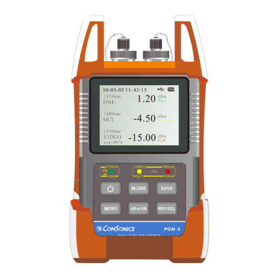
PON-3 / Operation 5. Operation Video/OLT 5.1 Layout The front panel is divided to two parts: 10-03-03 11: 43:15 1.20 Part I – LCD Display -4.50 -15.00 Part 1 Part II - Key Matrix and LED Indicators The device shows the test results on the LCD screen, as PON-3 well as the status by the LED’s. - Page 13 PON-3 / Operation 5.2 Key Functions Power Switch: Hold >2s: Switches unit on and off Press: Toggles Auto-off function off and on SAVE: Press and Hold to Save current data Menu mode: Left arrow MENU: Enter menu mode, press again to exit...
-
Page 14: Definitions
Maximum level for a Pass, Signal cannot be greater than this value Threshold2: Minimum level needed for a Pass. Below this level is either a warning condition. Threshold3: Lower limit for Fail. Below this level is a Fail condition. Limit2: Lower limit of the PON-3 measurement capability of the meter... -
Page 15: Quick Operation
PON-3 / Operation 5.4 Quick Operation 1. Connect the instrument to the optical link under test. 2. Press the Power key to turn on the instrument. 3. Press the MENU key to enter the menu mode. Select the “Threshold” option using the dBm/dB key as the down arrow and REF/SEL key to Select the option. -
Page 16: Detail Operation
PON-3 / Operation 5.5 Detailed Operation 5.5.1 Powering On the Instrument Press the Power key to turn on the instrument. It will automatically start making measurements. The auto-off feature defaults to ON and is shown in the bottom of the LCD screen. If you want to turn it off, press the Power key and release quickly (less than 2 seconds) to deactivate Auto shut down function. -
Page 17: Test Mode Switch
PON-3 / Operation 5.5.2 Test mode: In the test menu, press the Mode key to switch between the normal test mode and Pass/Fail indicator mode. 10-03-03 11: 43:15 1.Normal test mode Normal test mode does not use the threshold values and just displays the optical power measurements. -
Page 18: Threshold Setup
The user can select from 10 different Threshold settings that have been preset. The Threshold values are set up using the PC software and cannot be entered from the meter. A threshold name can also be assigned using the PC software. The PC software can be obtained from the ComSonics website, www.comsonics.com, under the resources download section. -
Page 19: Time Setup
PON-3 / Operation 5.5.4 Time Setup In the Menu mode, choose "Time" to setup up the data and time, see Fig. 4. 10-03-03 11: 43:15 Time Setup 08-10-25 15:02:03 Fig.4 Time Setup Menu In the time setup menu, the Save key becomes the left arrow key - use it to move the cursor. When the cursor moves to a number, the user can use ▲... - Page 20 PON-3 / Operation 5.5.5 dBm/dB Key for Unit Switching When the instrument is in the normal test mode, pressing dBm/dB can switch the units between dBm and dB. The dBm unit is the actual absolute power and dB unit is a power value relative to reference value. Refer to next section about “Reference value setup”.
-
Page 21: Reference Value Setup
PON-3 / Operation 5.5.6 Reference Value Setup In the test menu, press REF/SEL key for more than 2 seconds, then the LCD will display REF in red (see Fig. 5). This will set the current measurements as the Reference values. The test results after setting the reference are relative to the reference value which is useful to measure deltas. -
Page 22: Backlit Setup
PON-3 / Operation 5.5.7 Backlight Setup In the menu mode, select "Backlight" to enter to the setup menu for the backlight. See Fig. 7. 10-03-03 11: 43:15 Fig.7 Backlit Setup Menu In this menu, press the ▲ (Mode) key to brighten the backlight and the ▼ (dBm/dB) key to lower the backlight. After completing the setup, press REF/SEL key (less than 2 sec) to save the setting, and exit back to the menu mode. - Page 23 PON-3 / Operation 5.5.8 Memory Save Function Interface: On the main interface, the current record number is shown on the bottom left of the page. In the example shown on the right, the record number is “num: 0024” There is a 1,0000 record maximum that can be stored.
- Page 24 PON-3 / Operation At the data or "record” view (refer to Figure 10), the total number of records stored in the meter is shown at the top-left corner next to the wavelength columns. The values or word indicators under the header represent the measurements for each storage record.
-
Page 25: Remarks
PON-3 / Remarks 6. General Remarks 1.When battery power is low, the battery indicator will flash. Use the AC/DC adapter or charge the instrument/battery. 2.While charging, the charging indicator will be active on the LCD screen to show the battery charge status. -
Page 26: Recommendations
PON-3 /Recommendations 7. Recommendations: 1) Please use the dust-protection caps to prevent the connectors from contamination when the device is not in use. 2) Keep the optical connectors away from oil, dirt and other contamination to ensure the proper operation.
Need help?
Do you have a question about the PON-3 and is the answer not in the manual?
Questions and answers