
Subscribe to Our Youtube Channel
Related Manuals for ComSonics Companion


Summary of Contents for ComSonics Companion
- Page 1 CATV Digital / Analog Signal Level Meter with Active and Passive Ingress Testing USER GUIDE CSI Doc. 101453-001...
- Page 2 Fax: 1-540-432-9794, Email: tech-support@comsonics.com. Copyright All material in this manual is the property of ComSonics, Inc. and protected under the United States copyright law. No material shall be reproduced or used in any form or by any means (graphic, electronic, or mechanical, including photocopying,...
-
Page 3: Table Of Contents
Configuration Utility Installation Windows XP Configuration Utility Installation ..........34 Windows 7 Configuration Utility Installation ..........38 Test Companion to Computer Communications (XP and 7) ...... 41 Test Server Setup ................... 43 Test Server Placement Recommendation ..........45 Standard EIA Channel Table................47 Specifications .................... - Page 4 Companion Configuration and Charging Power Button Connector (Mini USB) 1 - 8 0 0 - 3 3 6 - 9 6 8 1...
-
Page 5: Introduction
Companion purchases or as a special order. Unpacking The Companion and its accessories are included in a shipping container designed to provide the maximum protection during shipment. Immediately upon receipt, inspect the container and contents for signs of physical damage. Notify the freight forwarder of any damage detected. -
Page 6: General Operation
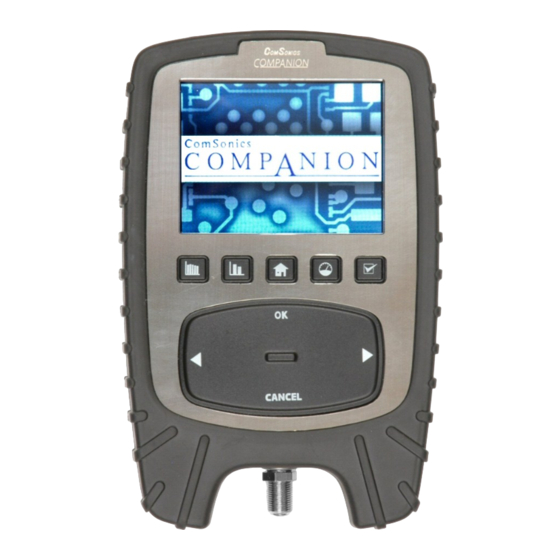
Companion General Operation The Companion front panel is equipped with five function buttons. Located below the function buttons are several cursor controls; OK, CANCEL, Left / Right arrows, and a touch rotary control. The power On / Off button is located on the upper right side of the case. -
Page 7: Power On, Home
Remaining Charge Remaining When a charger or PC cable is connected to an operating Companion, the battery symbol color changes to white and the segments cycle from left to right. w w w . c o m s o n i c s . c o m... -
Page 8: Favorite Channels
Companion Favorite Channels The screen shows five Favorite Channels in a vertical bar display combination. The Visual carrier level is displayed for analog channels and the digital multiplex power is displayed for digital channels. Digital channels are displayed with a graphic offset for ease of visual refer- ence. -
Page 9: Single Channel, Analog
Single Channel, Analog The screen shows a single channel in a vertical bar display. Based on the active configuration setting, the channel is displayed in the proper analog format. Scaling of the display is per- formed automatically. The analog V-A value is calculated as the difference between the video and the audio carrier levels. -
Page 10: Single Channel, Digital
Configuration Notice Applies to the Throughput mode on the next page. The Companion must be provisioned in the system with the throughput server address configured to complete the full Throughput test. If a non provisioned server address is set, the downstream and upstream levels are displayed but the test stops with a server error message. -
Page 11: Throughput
Press another function button to exit the Throughput mode. Note: The Companion must be provisioned in the system with the throughput server address configured to complete the full Throughput test. See page 54 for additional notes on the Throughput Test Sequence. -
Page 12: Reverse Path Analysis
Note: With Companion firmware 3.5 or greater, user adjustments made in the Reverse Path Analysis display are retained, even when the unit is powered off, with the exception of the Display Mode being reset to Normal when the unit is powered With Companion firmware 3.3 or less, user adjustments made in the Reverse... -
Page 13: X-Ray Reverse Ingress
The Companion X-Ray system enables the user to measure shielding integrity in the range of 100 dB (very good) to 20 dB (very poor). For easy status determination, each measurement includes a PASS or FAIL indication, based on the threshold value selected in the PC Configuration Utility. -
Page 14: Auto Test
Refer to page 20 for Auto Test Setup. If the active configuration setting does not have an associated auto test, the Companion displays a No Test File for Selected Config message . Press the Auto Test function button or select Auto Test on the HOME(2) screen to initiate the auto test routine. - Page 15 Auto Test - 2 IMPORTANT: Connect the Companion to the upstream path before starting Reverse Path. Example: drop cable side of customer ground block. Highlight the Reverse Path icon and press OK. If test results already exist with the same ID name, a confirmation window appears.
-
Page 16: Config(Uration) Select
The name of the active configuration setting is displayed on the HOME and HOME(2) screens. Note: Configuration Settings listed in a Companion can only be deleted by using the PC Configuration Utility. Refer to page 16 for information on creating configuration settings. -
Page 17: Upload Test Data
The Upload Test Data function transfers all stored test data from the Companion and then clears all test data from the Companion. The Companion must be provisioned to operate on the network (cable system) being tested and that a server/computer must be configured to receive and store... -
Page 18: Quick Guide
Example: HOUSE DROP is downloaded as HOUSE_DROP. IMPORTANT The Download Group function removes all stored configuration settings from the Companion and installs only the configuration settings in the current group. 1 - 8 0 0 - 3 3 6 - 9 6 8 1... -
Page 19: Overview
Configuration Utility Overview Utility Version 3.3 The Companion is shipped configured to the settings indicated as factory default value. Use the PC Configuration Utility Software to create custom configuration settings. The utility kit consists of an installation disk and a USB cable. The software requires a modern PC running MS Windows 2000, XP, Vista, or 7;... -
Page 20: Customize Settings
Run the Configuration Utility Double-click on the Companion Multiplan Config desktop icon to start the utility. From the All Programs list, move the pointer to ComSonics, Inc > Companion Multiplan Config and left click. The Settings screen initially displays the default configuration settings. After the initial use, the last used configuration setting is automatically loaded on startup. -
Page 21: Configuration Items
The Throughput Screen section has settings for pass / fail criteria and the downstream home channel. If ‘none’ is set or the specified home frequency is not found, the Companion performs a search for a downstream data channel. The Units of Measure section allows selection of dBmV or dBµV. - Page 22 PASS / FAIL indication. This mode performs the complete throughput measurement function. This mode is active with a valid IP address in the Throughput Server box and the Companion is properly provisioned for the system. The Companion displays the downstream and upstream levels;...
-
Page 23: Channel Setup Screens
The ID order is fixed and cannot be edited. Duplicate channel frequencies are not allowed. After download, channels are in order of frequency in the Companion. w w w . c o m s o n i c s . c o m... -
Page 24: Auto Test Setup
Companion firmware 3.2 or greater.) Click the Calculate Time button for an estimate of the Total Test Duration the Companion will require to perform the selected tests. If the test criteria is changed, click the Calculate Time button to update the time estimate. - Page 25 (if one exists) from the Companion. The Auto Test data results, stored in the Companion, remain intact until the utility’s Retrieve Auto Tests Results from Unit or the Companion’s Upload Test Data function is used. See next section.
-
Page 26: Group Download
Companion Group Download - 1 (The Group Download function requires Companion firmware 2.6 or greater.) Configuration settings can be downloaded one at a time from the Settings screen or in groups from the Group Download screen. To utilize the group download function, first use the Settings screen to create and save several custom configuration setting files. - Page 27 The first step of the group download process is to erase all configuration settings from the Config Select list in the Companion. To individually add or delete configuration settings in the Companion, use the functions on the Settings screen. Select a group name and use the Download Group button.
-
Page 28: Miscellaneous Detail
Firmware 2.5 or lower: Installs the currently displayed configuration setting to the Companion. The new configuration setting replaces the previous one. The Companion power must be cycled to activate the new configuration setting. Save Settings to File Use a meaningful name and store custom configuration settings. - Page 29 Note: During installation, a shortcut icon is created on the PC desktop to aid in locating the retrieved test results. Data files are named by the alphanumeric characters entered on the Companion prior to performing an auto test. Channel Test data files are identified by xxxxxxx.csv.
-
Page 30: Download Firmware
Access the ComSonics home page at http://www.comsonics.com. Click on the Downloads tab. On the Downloads page click on Updates. Click on the Companion Firmware update file name. Select the Save option in the File Download window. Use the browse function from the Save As window to place the firmware update file in a desired location on your computer. - Page 31 Download Firmware - 2 Open the Companion Configuration Utility. Power on the Companion and connect the USB configuration cable. Under the Tools menu, select the Download Firmware. The Open window appears. Browse to the location of the saved firmware file. Click on the firmware file to select it.
-
Page 32: Download Modem Firmware
Download Firmware. File System Integrity Check Use this function to routinely test the unit’s file system. Connect the Companion, and select File System Integrity Check under the Tools menu. If a no response message appears, see the section on Select Port. -
Page 33: Select Port
Your Firmware Version does not support this feature. Unplug the USB cable from the Companion and then reconnect the cable to establish the initial connection between the Companion and the computer. On the Settings screen, click the Refresh button to test operation. -
Page 34: Update Calibration File
Companion Update Calibration File - 1 The Configuration Utility features a function to field update a Companion from a factory calibration file of V1.x to a calibration file V2.x_Updated. Companion calibration V1.x is based on the Standard EIA channel set. - Page 35 Update Calibration File - 2 The uploaded file is converted to a V2.x format and downloaded to the unit. Click Close when the download is complete. To complete the calibration file update process, turn the unit off and then on, and press a measurement function button.
-
Page 36: Warning Messages, Download
2.0 Updated in order to be compatible with Companion Configuration Utility version 3.0 or higher. The calibration version is listed on the first information screen in the Companion. Refer to page 3 on accessing the information screens. Refer to page 30 on calibration file updating. -
Page 37: Battery Replacement
A fresh battery pack must be fully charged before use. Charge the new battery pack overnight. The Companion must be powered off to fully charge the battery. Continuous operation of the unit while connected to a charger is not possible as the battery will become depleted. -
Page 38: Windows Xp Configuration Utility Installation
Companion Win XP Configuration Utility Installation - 1 Important: Install the Utility Software before connecting the Companion. See page 38 for Windows 7. Place the installation disk into the drive. The installation automatically starts. Follow the on-screen instructions. If the auto-start function is turned off, follow the instructions below to manually install the program. - Page 39 Note the update message: Use Windows Updates to check for any critical updates to the .NET Framework. Double click the Companion Multiplan Config desktop icon and the Companion splash screen appears briefly. The Companion Settings window appears.
- Page 40 Companion Win XP Configuration Utility Installation - 3 Important: Install the Utility Software before connecting the Companion. Connect the Companion Plug the standard USB connector of the configuration cable into an available USB port on the computer. Plug the mini-USB connector end into the configuration port on the Companion.
- Page 41 New Hardware Wizard window. If the Cannot Start this Hardware message appears, click Finish, unplug the USB cable from the Companion, and then reconnect the cable to complete the hardware installation. Continue on page 41. w w w . c o m s o n i c s . c o m...
-
Page 42: Windows 7 Configuration Utility Installation
Companion Win 7 Configuration Utility Installation - 1 Important: Install the Utility Software before connecting the Companion. See page 34 for Windows XP. Place the installation disk into the drive. The installation automatically starts. Follow the on-screen instructions. If the auto-start function is turned off, follow the instructions below to manually install the program. - Page 43 Win 7 Configuration Utility Installation - 2 Click Next in the Confirm Installation window. If a version of the Configuration Utility exists, an ‘unable to install’ error message appears. Uninstall the current utility version under Control Panel > Programs and Features. Installation progress is shown.
- Page 44 Plug the standard USB connector of the configuration cable into an available USB port on the computer. Plug the mini-USB connector end into the configuration port on the Companion. The Companion must be powered on for communications to the PC. Refer to the illustration on page iii.
-
Page 45: Test Companion To Computer Communications (Xp And 7)
Your Firmware Version does not support this feature. Unplug the USB cable from the Companion and then reconnect the cable to establish the initial connection between the Companion and the computer. On the Settings screen, click the Refresh button to test operation. - Page 46 Win XP: Control Panel > System > Hardware tab > Device Manager Win 7: Control Panel > Device Manager Select View and Devices by type. Click on Ports (COM&LPT). The Companion appears as Gadget Serial (COMx). Note the COM port number. It is used in the Configuration Utility port selection.
-
Page 47: Test Server Setup
A user supplied static IP address, Gateway, and Primary and Alternate DNS servers (if in use) are required for operation of the Companion Throughput test. This information is needed to configure the Network Storage Link. Note: Off-the-shelf versions of the Linksys Network Storage Link will not ... - Page 48 Test Server Setup - 2 NOTE: If a SSH client is not available, a freeware program such as PuTTY may be used. The PuTTY application is provided on the Companion CD. It may be downloaded from the official PuTTY website: http://www.chiark.greenend.ogr.uk/~sgtatham/putty/download.html...
-
Page 49: Test Server Placement Recommendation
Test Server Setup - 3 12. The script prompts to change the domain name. a. The default domain name is shown in brackets. b. This entry does not need to be changed for operation of the NSLU2. c. You may change the domain name or press Enter to accept the default. 13. - Page 50 Companion Blank Page 1 - 8 0 0 - 3 3 6 - 9 6 8 1...
-
Page 51: Standard Eia Channel Table
Standard EIA Channel Table North American Standard shown here for example. (Additional basic channel formats can be found by using the Restore Factory Settings button.) Important Notice Channels 136 through 152 are only available in Companions with factory installed V2.x calibration file. -
Page 52: Specifications
Companion Specifications Analog Television 54 to 963 MHz (USA)*; 88 to 963 MHz (Euro) Signal Level Range -30 to +30 dBmV (30 to 90 dBµV) Auto Level Range 5 dB steps, max 20 dB Video Signal Level ±2.0 dB accuracy Audio Signal Level ±2.0 dB accuracy... -
Page 53: Companion Package / Accessories
Companion Signal Level Meter 101550-001 Euro Companion AC Charger 100-240VAC 101456-001 (North America plug type, Euro adapter) Companion Carry Case 101461-001 Companion Configuration Utility Software Kit 101458-001 (software and cable) Configuration Cable only CC-945 (PC - USB to mini USB) Companion Battery 101457-001... -
Page 54: Limited Warranty
Software: ComSonics warrants to the Customer that the Workstation Application software will perform in substantial conformance to program specifications for a period of ninety (90) days from the date of original shipment. ComSonics warrants the media containing software against failure during the warranty period. - Page 55 (including negligence) or any other theory, even if ComSonics has been advised of the possibility of such damages. ComSonics entire liability shall be limited to replace- ment, repair, or refund of the purchase price paid, at ComSonics’...
-
Page 56: Software License Agreement
Carefully read the following terms and conditions before using this product. It contains software, the use of which is licensed by ComSonics, Inc. to you, the original end user, for your use only as set forth below. If you do not agree to the terms and conditions of this agreement, do not use the software. - Page 57 Entire Agreement: This License Agreement and the accompanying Limited Warranty set forth in the entire agreement between you and ComSonics, supersedes all prior agreements, whether written or oral, with respect to the Software, and may be amended only in a writing signed by both parties.
-
Page 58: Notes On Throughput Test Sequence
Displays ‘PASS’ or ‘FAIL’ and ‘Press OK to Rerun Test’ Throughput Server Options Two options for server hardware: 1. Optional ComSonics supplied Linksys Network Storage Link unit Server software is preloaded at ComSonics Network settings are configured by the user ... - Page 59 w w w . c o m s o n i c s . c o m...
- Page 60 Harrisonburg, Virginia 22801 USA Phone: (540) 434-5965 USA Toll Free: (800) 336-9681 Fax: (540) 434-9847 Email: info@comsonics.com Internet: www.comsonics.com © 2007-2012 ComSonics, Inc. All Rights Reserved Document 101453-001 Rev. L Configuration Utility V3.3 Multiplan, FW 3.5, Modem FW 12 2012-09-05 sh...
Need help?
Do you have a question about the Companion and is the answer not in the manual?
Questions and answers