Table of Contents
Advertisement
Quick Links
Advertisement
Table of Contents

Related Manuals for Exhausto VEX5000 Series


Summary of Contents for Exhausto VEX5000 Series
- Page 1 VEX5000 R A N G E M O D U L E S VEX5000 Assembly, installation and maintenance instructions Original instructions EXHAUSTO A/S Tel.: +45 65 66 12 34 Odensevej 76 Fax: +45 65 66 11 10 5550 Langeskov, exhausto@exhausto.dk Denmark www.exhausto.dk...
-
Page 2: Table Of Contents
3005831-2019-04-01.fm 1. Introduction 1.1 Use ........................6 1.2 Unit configurations ....................6 2. Handling and transport 2.1 Transport and delivery ..................7 2.1.1 Once the VEX has arrived at the assembly site ........... 7 2.1.2 Extent of the delivery ..................7 2.1.3 Weight ...................... - Page 3 3005831-2019-04-01.fm 6. Startup 6.1 Start-up procedure..................... 29 6.1.1 Fans start-up ....................29 7. After commissioning 7.1 After 2–3 weeks of operation ................31 8. Maintenance 8.1 Replacement of filters ..................32 8.2 Filter design......................33 8.3 Cleaning......................33 9. Technical specifications 10.
- Page 4 Failure to observe instructions marked with a danger symbol may result in personal injury and/or damage to the unit. Instruction manual This instruction manual is for use with EXHAUSTO VEX type air handling units. Please application refer to the product instructions regarding accessories and extra equipment.
- Page 5 3005831-2019-04-01.fm Information plate The sections’ information plate can be read. • VEX size and designation for the section. • Production number and production year. • Maximum and minimum short-circuit current. • Supply voltage and the maximum current consumption. • Section number and the total number of sections for the air handling unit •...
-
Page 6: Introduction
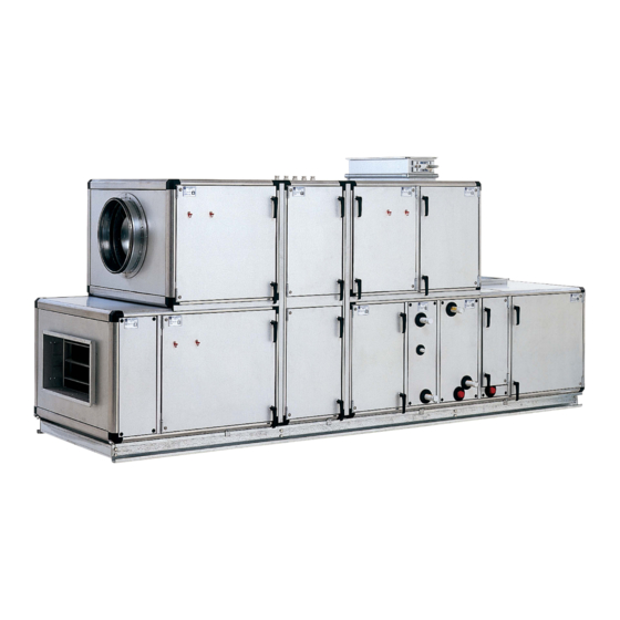
Introduction 3005831-2019-04-01.fm 1. Introduction 1.1 Use VEX5000 covers a wide capacity range, from 4,500 to 50,000 m³/h, with nine different unit sizes (VEX5020 - VEX5200), which means it is ideal for comfort ventilation in many types of buildings - from schools, institutions and offices, to hotels, hospitals and industrial premises. -
Page 7: Handling And Transport
Handling and transport 3005831-2019-04-01.fm 2. Handling and transport 2.1 Transport and delivery 2.1.1 Once the VEX has arrived at the assembly site • Check the air handling unit and any supplied accessories for any transport damage immediately on arrival at the assembly site. •... -
Page 8: Weight
Handling and transport 3005831-2019-04-01.fm Optional – can be • Water trap supplied as loose The crossflow heat exchanger and cooling coils are supplied with a water trap for parts connection to an external drain. • Flexible connections External connections for connection to duct system of the inlet and outlet openings are supplied with assembly rails. -
Page 9: Storage
Handling and transport 3005831-2019-04-01.fm Single section Single sections are equipped with transport feet and lifting eyes in the top corners. The lifting eyes may only be used on sections weighing less than 1500 Assembled air When lifting the assembled unit on a base, use a lifting beam. handling unit •... -
Page 10: Mechanical Assembly
Mechanical assembly 3005831-2019-04-01.fm 3. Mechanical assembly The VEX5000 air handling unit must be installed on a stable surface with a strong foundation. Setting up of the air handling unit 1. Set up the air handling unit. 2. Remove the fan unit’s transport safety fitting, if this is fitted. 3. -
Page 11: Setting Up The Base
Mechanical assembly 3005831-2019-04-01.fm 3.1.2 Setting up the base Place the base on a suitable installation site that has a foundation and which has been prepared. If the base is separated, assemble the cross members using mounting tabs. 1. Fit a levelling screw under each tab joint. 2. - Page 12 Mechanical assembly 3005831-2019-04-01.fm 4. Remove the lifting eyes once the section is positioned on the base or on an underlying section. 5. Fit the plastic covers and plug the holes. Sealing strip 6. Stick the sealing strip onto the contact surface along the inner edge on the section before positioning the adjacent section.
- Page 13 Mechanical assembly 3005831-2019-04-01.fm To access the inside of the air handling unit, do so through the inspection doors or by removing a side panel. If necessary, pull out functional parts that are in the way. Fit screws in the fitting and tighten in a cross pattern, using a 6 mm hex key until there is a gap of approx.
-
Page 14: Fitting Roof (Outdoor Air Handling Units)
Mechanical assembly 3005831-2019-04-01.fm 3.2 Fitting roof (outdoor air handling units) 3.2.1 Preparation The roof is built up of a number of pre-fabricated roofing panels, of various lengths between 280-560 mm. The roofing panels come in different sizes - but calculated to match the roof-size. It is recommended that the roofing panels are laid loosely before they are secured, to ensure that all of the panels are positioned correctly. -
Page 15: Fitting Of Roof
Mechanical assembly 3005831-2019-04-01.fm 3.2.2 Fitting of roof 1. Seal between the sections. 2. Stick the sealing strips on the top of the air handling unit on all of the outsides (A). 3. Lay the U profile along (in the middle) the air handling unit as a roof ridge, to achieve a fall toward the sides. - Page 16 Mechanical assembly 3005831-2019-04-01.fm 1. Start with the 2-part roofing panel 2. Assemble the 2-part roofing panel using the mounting tab. 3. Fit the assembled plates on the rotor. 4. Seal the plate joint. 5. Fit the four end piece corners. 6.
-
Page 17: Baffel Plate
Mechanical assembly 3005831-2019-04-01.fm 3.2.3 Baffel plate For fans with free outflow without duct connection, fit baffel plate on the outflow ends. Keep the baffel plate at the correct distance using 6 or 8 braces. 1. Bend the braces in the square holes so that they align with the holes in the baffel plate. -
Page 18: Fans
Mechanical assembly 3005831-2019-04-01.fm 3.3 Fans Important: If there is not a duct on the pressure side of the fan, a protective net must be fitted. 3.3.1 Transport safety fitting The transport safety fitting is marked with a yellow label. The fan unit can be equipped with a transport safety fitting, which locks the vibration damping for the unit. - Page 19 Mechanical assembly 3005831-2019-04-01.fm 3.3.2 Airflow determination The airflow can be determined on the basis of the pressure difference across the fan (∆P) and the fan’s calculation constant (K). Example: Plenum fan Pressure difference is calculated in Pascal(Pa) and using the equation shown below, the airflow (q) is determined in m P x K = q Example: The airflow is calculated for a fan of the type ER/RH63C.
-
Page 20: Handles On Doors
Mechanical assembly 3005831-2019-04-01.fm 3.4 Handles on doors The handles can be supplied loose to avoid damage during transport and are supplied as loose parts in packaging. A set of handles consists of 1 handle with lock and key, and one handle without a lock. The lockable handle must be fitted at a suitable height. Exercise caution with the handle when opening the door. -
Page 21: Filter Monitor (Optional)
Mechanical assembly 3005831-2019-04-01.fm 3.6 Filter monitor (optional) Filter condition The condition of the filter is determined by the pressure drop measured across the filter. You may choose between two types of gauges. U pipe manometer Magnehelic pressure gauge 3.6.1 Filling with liquid 1. -
Page 22: Rotary Heat Exchanger
The LON module can also be retrofitted as a LonWorks kit. ® EXHAUSTO provides a LonWorks kit, which consists of a module and visit by a technician, who will fit and configure the control system. Contact EXHAUSTO for more information. 22/64... -
Page 23: Pipe System
Pipe system 3005831-2019-04-01.fm 4. Pipe system The plumbing work must be carried out by an authorised plumber. The pipe system that connects the cooling and heating coils and exchanger must be equipped with a pump, regulating and monitoring equipment. The pipe system must be protected from frost damage via a built-in control system, which opens the valve for water flow, stops the fan and closes the damper against outdoor air if there is a risk of frost damage. -
Page 24: Circuit For Heating Coil
Min. 60 kPa diff. pressure Extra pump activated by low diff. pressure Supply Max. 5 m Filter* Shut-off valve* Motor valve Thermometer 4.0.3 Circuit for liquid coupled heat exchanger Motor valve Temperature sensor Expansion tank* *Not supplied by EXHAUSTO. 24/64... -
Page 25: Condensation Outlet
Pipe system 3005831-2019-04-01.fm 4.1 Condensation outlet 4.1.1 Establishment of condensation outlet The connection must be made by an authorised plumber. The execution of the condensation outlet must take into consideration that the doors must be able to be opened, and that inspection, servicing and operation of the air handling unit should be unhindered. -
Page 26: Electrical Installation
An isolation switch must be installed immediately preceding the air handling unit in accordance with EN60204-1. NB: The isolation switch is not supplied by EXHAUSTO. In Denmark, the DS/HD 60364 series and DS/EN 60204-1 must be complied with. In the EU, the directive relating to machine safety –... -
Page 27: Running Of Cable Through Panels
Electrical installation 3005831-2019-04-01.fm NB: The connection of the power supply is done in connection with the start-up of the air handling unit. See the section “Start-up”. 5.3 Running of cable through panels Cables routes running through the panels in the air handling unit housing must be airtight and made safe against damage from sharp panel edges. - Page 28 ® Note: The procedure assumes that a LON module has been installed. Contact EXHAUSTO for more information retrofitting. ® Setting up of LON communication is carried out after start-up and requires a log in as the Installer. For more information about setting up communication, see EXcon instruction manual - VEX5000 Control System.
-
Page 29: Startup
9. Check again that the damper shuts out the air. 10.Switch on the fans. Note Air handling units with control systems from EXHAUSTO use approx. three minutes to start up: • Approx. 30 seconds after the voltage is switched on, logging can take place using a browser or the handheld terminal. - Page 30 Startup 3005831-2019-04-01.fm 11. Check that the level of vibration is normal. The level should not exceed 7 mm/s, measured at two points with 90° offset ® externally on the fan pipe (ZerAx fans) or inlet funnel (plenum fans) and the free ends of the motor.
-
Page 31: After Commissioning
After commissioning 3005831-2019-04-01.fm 7. After commissioning 7.1 After 2–3 weeks of operation Check the rotor’s belt and remove any shavings which have blown out from the fins. It is quite normal to find shavings after start-up. Trin Handling Check for shavings in the bottom of the rotor section. Shavings can come from the belt or from the manufacture of the rotor. -
Page 32: Maintenance
3005831-2019-04-01.fm 8. Maintenance The VEX5000 series has been designed to not require any maintenance. The air handling unit shall be cleaned and the filters replaced when they are worn out. This is important because it ensures the air handling unit retains its efficiency and that there is a good hygienic indoor climate. -
Page 33: Filter Design
Maintenance 3005831-2019-04-01.fm 8.2 Filter design See below for an overview of the filter design and filter size that apply to VEX sizes. To order filters, contact EXHAUSTO. Filter without base tray Filter with base tray 8.3 Cleaning Disconnect power via the isolation switch before cleaning. The doors may only be opened after the air handling unit has stopped. -
Page 34: Technical Specifications
Technical specifications 3005831-2019-04-01.fm 9. Technical specifications 5020 5050 5080 5090 5100 5130 5160 5180 5200 Air handling unit data Max. airflows /h 4500 10,800 16,200 21,500 20,000 32,000 40,000 45,000 50,000 Damper Protection class DS/EN 1751, class 2, 3 or 4 Filter types G2, G4, M5, F7 or F9 Crossflow heat exchanger... -
Page 35: Technical Electrical Connections (Excon Control System)
The subsequent installation of components requires a reconfiguration of the control system and requires another pin allocation than that shown. Contact EXHAUSTO for more information. EXcon Master The figure shown below is found in the web user interface under Service > Master >... - Page 36 Technical electrical connections (EXcon control 3005831-2019-04-01.fm Fan IO 1 (supply The figure shown below is found in the web user interface under Service > Fan IO> air) Fan-IO 1 >Connection EXcon Fan-IO 1. Fan IO 2 (extract The figure shown below is found in the web user interface under Service > Fan IO> air) Fan-IO 2 >Connection EXcon Fan-IO 2.
-
Page 37: Connection Diagrams
Technical electrical connections (EXcon control 3005831-2019-04-01.fm 10.2Connection diagrams 10.2.1 Terminal block (50A & 100A) (32A) 3x400VAC +Neutral 3x400VAC +Neutral PE,L1,L2,L3,N PE,L1,L2,L3,N 37/64... -
Page 38: Rotary Heat Exchangers
Technical electrical connections (EXcon control 3005831-2019-04-01.fm 10.2.2 Rotary heat exchangers Blue Brown Black Green Black Blue Black Brown Brown White Yellow Green Fig 10.2.2.1 Main supply – rotary heat exchangers 38/64... - Page 39 Technical electrical connections (EXcon control 3005831-2019-04-01.fm Temp. water-based heating Frost sensor Temp. room 0-10V 0-10V VAV extract air CO2-sensor 0-10V VAV supply air Extended operation Cooling error Fire alarm External start/stop Fire thermostat Fig 10.2.2.2 Master input – rotary heat exchangers 39/64...
- Page 40 Technical electrical connections (EXcon control 3005831-2019-04-01.fm Operation relay B alarm A alarm Recirculation damper Circ. pump cooling Circ.pump heating 0-10V 0VAC Heating 24VAC 0-10V Cooling 0VAC 24VAC Fig 10.2.2.3Master output – rotary heat exchangers 40/64...
- Page 41 Technical electrical connections (EXcon control 3005831-2019-04-01.fm -P2+ filter -P1+ fan CAV -P2- filter -P1- fan CAV 24VDC 24V on/off 24V on/off Motor damper, outdoor air spring return Temp 2 Extract air temperature Supply air temperature duct sensor Temp 1 Green Alarm relay Yellow Alarm relay...
- Page 42 Technical electrical connections (EXcon control 3005831-2019-04-01.fm -P2+ filter -P1+ fan CAV -P2- filter -P1- fan CAV 24VDC 24V on/off White Motor damper, exhaust air On/Off Black 24V on/off Temp 2 Outdoor air temp. Temp 1 Exhaust air temp. Green Alarm relay Yellow Alarm relay Blue...
- Page 43 Technical electrical connections (EXcon control 3005831-2019-04-01.fm Fig 10.2.2.6 Internal connections – rotary heat exchangers 43/64...
-
Page 44: Crossflow Heat Exchangers
Technical electrical connections (EXcon control 3005831-2019-04-01.fm 10.2.3 Crossflow heat exchangers Blue Brown Black Green Black Fig 10.2.3.1 Main supply – Crossflow heat exchangers 44/64... - Page 45 Technical electrical connections (EXcon control 3005831-2019-04-01.fm Temp. water-based heating Frost sensor Temp. room 0-10V 0-10V VAV extract air CO2 sensor 0-10V VAV supply air Extended operation Cooling error Fire alarm External start/stop Fire thermostat Fig 10.2.3.2Master input – Crossflow heat exchangers 45/64...
- Page 46 Technical electrical connections (EXcon control 3005831-2019-04-01.fm Operation relay B alarm A alarm Recirculation damper Circ. pump cooling Circ.pump heating Bypass 0-10V damper 0VAC 24VAC 0-10V 0VAC Heating 24VAC 0-10V Cooling 0VAC 24VAC Fig 10.2.3.3Master output – crossflow heat exchangers 46/64...
- Page 47 Technical electrical connections (EXcon control 3005831-2019-04-01.fm -P2+ filter -P1+ fan CAV -P2- filter -P1- fan CAV 24 VDC 24 V on/off 24 V 24 V on/off Motor damper, outdoor air spring return Temp 2 Extract air temperature Supply air temperature duct sensor Temp 1 Green...
- Page 48 Technical electrical connections (EXcon control 3005831-2019-04-01.fm -P2+ filter -P1+ fan CAV -P2- filter -P1- fan CAV 24VDC 24V on/off White Motor damper, exhaust air On/Off Black 24V on/off Temp 2 Outdoor air temperature Temp 1 Exhaust air temperature Green Alarm relay Yellow Alarm relay Blue...
- Page 49 Technical electrical connections (EXcon control 3005831-2019-04-01.fm Fig 10.2.3.6 Internal connections – crossflow heat exchangers 49/64...
-
Page 50: Liquid Coupled Single String
Technical electrical connections (EXcon control 3005831-2019-04-01.fm 10.2.4 Liquid coupled single string Blue Brown Black Green Black Fig 10.2.4.1 Main supply – liquid coupled single string 50/64... - Page 51 Technical electrical connections (EXcon control 3005831-2019-04-01.fm Temp. water-based heating Frost sensor Temp. room 0-10V 0-10V VAV extract air CO2-sensor 0-10V VAV supply air Extended operation Cooling error Fire alarm External start/stop Fire thermostat Fig 10.2.4.2 Master input – liquid coupled single string 51/64...
- Page 52 Technical electrical connections (EXcon control 3005831-2019-04-01.fm Operation relay B alarm A alarm Recirculation damper Circ. pump cooling Circ.pump heating 0-10V 0VAC Heating 24VAC 0-10V Cooling 0VAC 24VAC Fig 10.2.4.3 Master output – liquid coupled single string 52/64...
- Page 53 Technical electrical connections (EXcon control 3005831-2019-04-01.fm -P2+ filter -P1+ fan CAV -P2- filter -P1- fan CAV 24VDC 24V on/off 24V on/off Motor damper, outdoor air spring return Extract air temp. Temp 2 * Only for supply air fan -T1, outdoor air sensor Supply air temp.
- Page 54 Technical electrical connections (EXcon control 3005831-2019-04-01.fm -P2+ filter -P1+ fan CAV -P2- filter -P1- fan CAV 24VDC 24V on/off Motor damper, White exhaust air On/Off Black 24V on/off Outdoor air temp. Temp 2 * Only for extract air fan -T3 extract air temp. Exhaust air temp Temp 1 Green...
- Page 55 Technical electrical connections (EXcon control 3005831-2019-04-01.fm Fig 10.2.4.6 Internal connections – liquid coupled single string 55/64...
-
Page 56: Electric Heating Coil
Technical electrical connections (EXcon control 3005831-2019-04-01.fm 10.2.5 Electric heating coil 56/64... -
Page 57: Serial Modbus Cable
Technical electrical connections (EXcon control 3005831-2019-04-01.fm 10.2.6 Serial Modbus cable RJ12 / 6 9 pol. D-sub hun RS485 B RS485 A 10.2.7 Rotor control Fig 10.2.7.1 VEX5010-5100 Fig 10.2.7.2 VEX5130-5200 10.3External connections 57/64... -
Page 58: Digital Inputs
Technical electrical connections (EXcon control 3005831-2019-04-01.fm 10.3.1 Digital inputs Master Din1 (fire thermostat) • Potential free contact, which trips in case of fire. • Fire thermostat • Smoke detector • Fire thermostat Master Din3 (external start/stop) • Potential free contact, which trips in case of stop. •... -
Page 59: Analogue Outputs
Technical electrical connections (EXcon control 3005831-2019-04-01.fm 10.3.3 Analogue outputs Master Aou1 (cooling) • 0–10 V Master Aou2 (heating) • 0–10 V Master Aou3 (heat recovery) • 0–10 V • Bypass damper motor 24 VAC (at 0 V the bypass is fully open) 10.3.4 Digital outputs Master Dout1 (heating relay) •... -
Page 60: Flow Diagrams
Flow diagrams 3005831-2019-04-01.fm 11.Flow diagrams Depending on the installed equipment level, there will be a difference between the actual and shown flow for the different air handling unit variants. VAV1 Outdoor air Supply air Rotor VAV2 Exhaust air Extract air Fig 11.1 Example of an air handling unit with rotary heat exchanger, water heating and cooling VAV1 Exhaust air... - Page 61 Flow diagrams 3005831-2019-04-01.fm Abbreviation Component Description Water: Fire thermostat BT70 Fire thermostat for supply air max. 70°C, positioned in the air handling unit Fire thermostat BT40 Fire thermostat for extract air max. 40°C, positioned in the air handling unit Constant airflow Pressure transducer for constant airflow regulation fitted internally sensor in room or duct Optional, supplied loose...
- Page 62 Spare parts 3005831-2019-04-01.fm 12.Spare parts Contact EXHAUSTO to order spare parts. Component Type Comments Spare V-belts for rotors Recovery valve, 3-way, VXP459.15-2,5 KVS 2.5, 1/2" incl. 1 set ALG143 Recovery valve, 3-way, VXP459.20-4 KVS 4.00, 1/2" incl. qty. 3 ALG15. ALG153 Recovery valve, 3-way, VXP459.25-6,3...
- Page 63 Spare parts 3005831-2019-04-01.fm 63/64...
Need help?
Do you have a question about the VEX5000 Series and is the answer not in the manual?
Questions and answers