
Related Manuals for Velleman WFS210


Summary of Contents for Velleman WFS210
- Page 1 WFS210 2CH WLAN DIGITAL STORAGE OSCILLOSCOPE WFS210 help manual for use with the PC & tablet © 2014 Velleman NV...
-
Page 2: Table Of Contents
3 Indications ........................... 9 4 Software controls ........................... 9 5 Trigger level ........................... 11 Part V Tablet application 1 WFS210 application ........................... 12 2 Measuring with Apple / Android ........................... 13 3 Gestures for tablet ........................... 14 Part VI Oscilloscope Terms 1 - A - ........................... - Page 3 Contents 14 - T - ........................... 19 15 - V - ........................... 19 16 - W - ........................... 20 © 2014 Velleman NV...
- Page 4 18 000 different products of 50 b rands. The distrib ution network includes more than 1700 distrib utors in well over 85 countries. Velleman® nv has b uilt up an excellent service reputation towards retailers. To meet the ever increasing growth, Velleman® nv expanded with new offices and showrooms as well as a new warehouse of 35 000m³...
-
Page 5: Part I Introduction
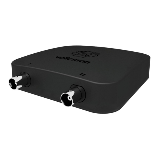
WFS210 2CH wlan Digital Storage Oscilloscope The Velleman WFS210 is the world’s first Wlan dual channel digital storage oscilloscope geared towards tablet computers, it's a compACt, portable, battery powered, fully featured two channel oscilloscope. As opposed to traditional oscilloscopes, it does not feature a screen. -
Page 6: Part Ii General Information
Cisco in the U.S. and other countries and is used under license. Android is a trademark of Google Inc. Windows is a registered trademark of Microsof t Corporation in the United States and other countries. © 2014 Velleman NV... -
Page 7: Safety & Warnings
Unsafe devices are: Equipment directly connected to mains (e.g. old TV sets) Equipment that contains components that are directly connected to mains (dimmers…). It is advisable, when measuring on above equipment, to use a isolation transformer. © 2014 Velleman NV... -
Page 8: Measuring Probe
(e.g. our PROBE60S type). When using the measuring probe in the X10 position, the measuring impedance will increase to 10Mohm, thereby reducing the measuring instrument's charge on the coupling. IMPORTANT: X10 measuring probes should be calibrated. © 2014 Velleman NV... -
Page 9: Probe Compensation
5. If the oscilloscope has a built-in calibration routine, run this routine for increased accuracy. 6. Repeat as necessary. © 2014 Velleman NV... -
Page 10: Part Iii Digital Storage Oscilloscope
Power on/off. USB / Charger connected. Caution: Probe ground and charger ground at different voltage level. Never use the WFS210 with a USB connection when the signal source is powered trough USB Battery full Battery charging © 2014 Velleman NV... -
Page 11: Connections
2. BNC inpuit connector channel 2 3. Power on/off 4. USB/charger connection 5. Reset SSID WLAN 6. Probe compensation testpoint Charging the battery It is recommended to charge the battery completely before using the oscilloscope for the first time. © 2014 Velleman NV... -
Page 12: Part Iv Pc Application
Connect: Connect the software application htrough USB or WLAN with the scope module Exit: Terminates the program Tools menu WLAN settings ==> SSID : Change the name of the WLAN network Help menu About: Displays information about the program version © 2014 Velleman NV... -
Page 13: Indications
Voltage/division measurement channel 2 Time base measurement Software controls Connect: Connect the software application with the WFS210 via USB or WLAN. Autorange: Automatic setup for the volts/div, time/div, and trigger level to produce a stable waveform of usable size. Time base: Selects the time setting for the beam to sweep one major division on the screen. - Page 14 The calculated power can be displayed for loads of 2, 4, 8, 16 or 32 Ohm. To choose the different loads, first highlight the power readout and then press the right cursor key. © 2014 Velleman NV...
-
Page 15: Trigger Level
PC application Trigger level TRIGGER Level : Selects the signal level at which the sweep is triggered. © 2014 Velleman NV... -
Page 16: Part V Tablet Application
PC application Tablet application WFS210 application ios / Android™ Search for the WFS210 application. © 2014 Velleman NV... -
Page 17: Measuring With Apple / Android
Tablet application Measuring with Apple / Android 1. Power on the WFS210 oscilloscope. 2. Slow blinking = creation of an access point successful. 3. Connect your tablet with the WLAN access point. Apple Android © 2014 Velleman NV... -
Page 18: Gestures For Tablet
4. Connect the Oscilloscope to a signal source. 5. Tap on the WFS210 app to open it. 6. The LED lights when the applications have been successfully connected to the WFS210 scope. 7. The scope is now ready for use. -
Page 19: Part Vi Oscilloscope Terms
CHANNEL This is the input circuit consisting a vertical attenuator, vertical amplifier and an input coupling network. CIRCUIT LOADING The unintentional interaction of the probe and oscilloscope with the circuit being tested which distorts a signal. © 2014 Velleman NV... - Page 20 The higher the resolution, the more levels are available and the more accurate the input signal can be reconstructed. DISTORTION Undesired alteration of a signal due to external causes such as overloaded circuits, badly designed circuits, etc… © 2014 Velleman NV...
- Page 21 AC and DC component of the signal are passed. Low frequency signals (<20Hz) should always be displayed using DC coupling. Should AC coupling be used, the internal coupling capacitor will interfere with the signal and the displayed signal will not be correct. © 2014 Velleman NV...
- Page 22 RIPPLE Unwanted periodic variation of a DC voltage. RISE TIME The time taken for the leading edge of a pulse to rise from its low to its high values, typically measured from 10% to 90%. © 2014 Velleman NV...
- Page 23 6.15 - V - VERTICAL SENSITIVITY An indication of how much the vertical amplifier can amplify a weak signal. Vertical sensitivity is usually measured in millivolts (mV) per division. VOLT The unit of electric potential difference. © 2014 Velleman NV...
- Page 24 WAVEFORM A graphic representation of a voltage varying over time. WAVEFORM POINT A digital value that represents the voltage of a signal at a specific point in time. © 2014 Velleman NV...
- Page 25 Legen Heirweg 33, B-9890 GAVERE, Belgium (Europe) Phone number: +32 (0)9 384 36 11 Fax (Velleman): +32 (0)9 389 93 35 web: www.vellemanprojects.eu Copyright Velleman©. Misprinting and modifi cations in images and text reserved.
Need help?
Do you have a question about the WFS210 and is the answer not in the manual?
Questions and answers