
Related Manuals for Niigata seiki LEVELNIC DL-S3L


Summary of Contents for Niigata seiki LEVELNIC DL-S3L
- Page 1 <精密級電子水準器> デジタルL型水準器 レベルニック 取扱説明書 DL-S3L 型式 ◎お読みになった後は、お使い になる方がいつでも見られる 所に必ず保管して下さい。...
- Page 2 この度は のレベルニックをお買い求めいただきましてあり がとうございます。 ご使用に際し、 本器の性能を十分に発揮していただくために、 本説明書を最後 までお読みいただき、 正しい使い方により、 末長くご愛用下さいますよう、 お 願い申し上げます。 目 次 概 要 2 ・ ・ ・ ・ ・ ・ ・ ・ ・ ・ ・ ・ ・ ・ ・ ・ ・ ・ ・ ・ ・ ・ ・ ・ ・ ・ ・ ・ ・ ・ ・ ・ ・ ・ ・ ・ ・ ・ ・ ・ ・ ・ ・ ・ ・ ・ ・ ・ 特 長...
- Page 3 概 要 本器はマイクロコンピュータを内蔵した、 高感度 ・精密級の振り子型電子水準 器です。 傾斜角に応じて得られる振り子の微小変位を、 電気信号として取り出し、 傾斜 をmm/mによる勾配とDEG (° )による角度のデジタル表示により直読でき ます。 特 長 ◎差動トランスを使用しているため、 極めて感度が高く安定しています。 ◎気泡管式の水準器に比べ、 広い範囲の測定ができます。 (±5mm/m、 ±0.286° ) ◎気泡管式の水準器に比べ素早く応答します。 (フルスケールの変位を与えた場合 :応答時間……約1 0秒) ◎読み取りやすいデジタル表示です。 ◎0コール、 1/2コールスイッチにより、 基準を決める、 表示を半分にするなど の作業がワンタッチでできます。 ◎スイッチ切り換えで、 mm/mとDEG (° )の二通りの表示ができます。 ◎モードスイッチにより最小読取桁を選択できます。 ◎測定値を有線で出力できます。 ( RS-232C準拠 ) ◎本器の裏表に表示パネルがありますので、 垂直測定の場合、 本器を左右どち らに向けても読み取れます。...
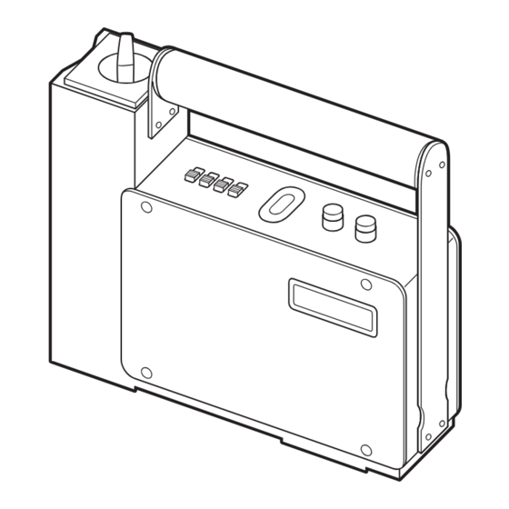
- Page 4 各部の名称 5 6 7 8 3 2 1 9 4 4 -3 -...
- Page 5 1 0コールスイッチ 2 1/2コールスイッチ・信号出力スイッチ 3 副気泡管 4 表示パネル (表面/裏面) 5 電源スイッチ 6 単位切り換えスイッチ 7 モードスイッチ 8 機能切り換えスイッチ 9 L型レベルベース 磁石ON ・OFFレバー 信号出力用ジャック ACアダプタ用ジャック バッテリーケース -4 -...
- Page 6 各部の機能 1 0コールスイッチ 0コールスイッチを押すと、表示はゼロになります。 スイッチは約1秒くらい押してください。 (エラー表示のときは機能しません。) 2 1/2コールスイッチ ・ 信号出力スイッチ ■1/2コールスイッチの場合 1/2コールスイッチを押すと、表示はスイッチを押した時点の表示 値の半分の値となります。 1/2コールはスイッチを離した時に表示値が変わります。 スイッチは約1秒くらい押してください。 (エラー表示のときは機能しません。) ■信号出力スイッチの場合 本器側で信号の出力を指示するためのスイッチです。 信号出力スイッチを押すと、信号出力用ジャックからRS-232C に準拠した信号で測定値が出力されます。 信号出力はスイッチを離した時に行なわれます。 スイッチは約1秒くらい押してください。 ケーブルが正しく接続されていない時や、通信中に異常が起きた場 合にはエラー(E1、E2)が約3秒間表示されます。 外部信号出力 詳しくは (P1 7) の項目をご覧ください。 ※どちらのスイッチとして機能させるかは、機能切り換えスイッチに より指定します。 3 副気泡管 ロール方向(測定軸に対して直角方向)の傾きを確認するためのもの です。 -5 -...
- Page 7 4 表示パネル (表面/裏面) 傾斜、バッテリーの電圧低下、通信の異常を表示します。 ■傾 斜 表示値は単位切り換えスイッチにより、mm/mとDEG ( ° ) の単位 で表示できます。 mm/mの表示とDEG ( ° ) の表示とを区別するために、DEG ( ° ) で表示している時は小数点より上の桁の0は表示されません。 傾斜が測定範囲を越えた時はエラー表示をします。 プラス方向のエラーの場合には「EEEE」、マイナス方向のエラー の場合には「-EEEE」の表示をします。 (磁石部を左側に見て、右側上がりがプラスになります。 ) 傾斜が測定範囲に戻れば通常動作に戻ります。 ■バッテリーの電圧低下 バッテリーの電圧が使用範囲よりも低下した場合、自動バッテリー チェック機能により表示値が点滅します。 表示値が点滅した時は、新しいバッテリーと交換するか、付属のAC アダプタをご使用ください。 ■通信の異常 信号出力を行なう時に、ケーブルが正しく接続されていない時や、 通信中に異常が起きた場合にはエラー(E1、E2)が約3秒間表示 されます。 外部信号出力 詳しくは (P1 7) の項目をご覧ください。 5...
- Page 8 各部の機能 つづき 6 単位切り換えスイッチ 表示値の単位をmm/mとDEG ( ° ) の どちらで表示させるかを指定します。 mm/mは1メートル当りの高低差を mm ミリメートル単位で表示します。 表示 DEG 表示 測定範囲は±5mm/mです。 DEG ( ° ) は角度で表示します。 1m 測定範囲は±0. 286° です。 7 モードスイッチ 測定値が±1.999mm/m、±0.1145° 以下の場合の最小読取桁 を指定します。 0.001の最小読取桁は0.001mm/m、 0.0001° となります。 0.01の最小読取桁は0.01mm/m、0.001° となります。 0.01の指定により消える桁は四捨五入されます。 必要な桁が0.01mm/m、0.001° で十分な時などに、表示のチラ ツキが少なく見やすくなります。 尚、...
- Page 9 磁石ON・OFFレバー レバーをOFFからONにすると、磁力が発生し本器を吸着できます。 ご注意:磁力が強いのでレバーをOFFにしても、多少磁力が残る 場合があります。 信号出力用ジャック RS-232Cに準拠した信号により、表示されている値を測定してい る単位と共に出力することができます。 外部信号出力 詳しくは (P1 7) の項目をご覧ください。 A Cアダプタ用ジャック 外部からの電源取り入れ用ジャックです。 付属のACアダプタをご使用ください。 ACアダプタの出力ソケットをACアダプタ用ジャックに差し込むと、 本器のバッテリーは内部回路から切り離されます。 バッテリーケース この中にバッテリーが収納されます。 ■バッテリーの収納方法 ドライバ等をケースの溝に挿入し、 - 持ち上げるようにしながら手前に引い てください。 次に、電池のプラス、マイナスを間違 えないようにケースへ収納し、そのま ま本体に押し込んでください。 ドライバ - ※電池は9V乾電池をご使用ください。 -8 -...
- Page 10 基準点移動による測定範囲の変化 ■0コールスイッチ、1/2コールスイッチにより、任意の表示値のところ でゼロ表示させたり数値を半分にしたりして、表示の基準点を移動させ ることができます。 ただし、測定範囲が表示値と本器内部に持っている内部数値(電源を入 れた時最初に表示される数値)により制限されます。 ■本器は水平のゼロ点を持っていません。 電源を入れた時最初に表示される内部数値のゼロは、必ずしも水平のゼ ロ点とは一致しません。 測定に水平のゼロ点が必要な時は、毎回電源を入れた時に一度水平のゼ ロ点をセットする必要があります。 これにより、毎回正しく調整された水平のゼロ点を基準として測定され、 ゼロ点の狂いによる誤差を無くすことができます。 水平のゼロ点をセットするために0コール、1/2コールの操作を行ない ます。 ゼロ点セッ ト 詳しくは (P13)の項目をご覧ください。 ■本器は水平のゼロ点を中心として±5mm/m、±0.286° (以降の数 値の説明はmm/mの単位で行ないます。)の測定範囲を確保するために、 内部数値のゼロ点と水平のゼロ点のずれを見込んで、内部数値で±5.25 mm/mを動作範囲としてあります。 表示値は±5mm/mを表示範囲としてあります。 測定範囲はこの2つの条件により制限されます。 -9 -...
- Page 11 ■測定範囲を示す図において、上に表示されている数字が本器が内部に持っ ている内部数値で、下に表示されている数字が表示パネルや外部信号とし て出力される数値です。(数値はmm/mの単位で説明しています。) ◎0コール、1/2コールをしていない場合 (表示の基準点が内部数値のゼロ点上にある) 内部数値 -5. 25 -5 0 +5 +5 . 25 (上) -5 0 +5 表示の基準点 (下) -EEEE 測定範囲 EEEE ◎0コール、1/2コールで表示の基準点が+0.1 mm/m移動した場合 (例)・+0.1mm/mで0コールを行なった、 ・+0.2mm/mで1/2コールを行なった など 内部数値 -5 .25 -4. 9 0 +0. 1 +5. 1 +5 . 25 (上)...
- Page 12 使用方法 本器は精密測定器ですので、落下やぶつけるなどの衝撃を与えないよう に十分注意してください。 (1)使用する前に、ホワイトクリーナーやアルコールなどを湿らせたきれ いなグラスペーパや布などで、本器のベース測定面及び本器が使用さ れる被測定物の測定面のゴミや油膜をきれいに拭き取ってください。 (2)被測定物の測定面に本器を置いてください。 (3)電源スイッチをONにしてください。 内部回路が約20分で安定しますので、その後測定を開始してくださ い。 電源を入れてから最初の20分で、0.01mm/m以下の量のゼロ点移 動が生じますが、この量が測定に差し支えなければすぐに測定を開始 していただいても構いません。 本器と被測定物との間には、温度差がないようにしてください。 より正確な測定を行なう場合は、一般の精密測定と同様に恒温室 内でのご使用をお奨めいたします。 (4)使用後は本器のベース測定面に防錆油を塗り、保管してください。 -11 -...
- Page 13 本器は表示パネル側(正面から見て右側)が上がるとプラスの数値で傾斜 を表示し、下がるとマイナスの数値で傾斜を表示します。 測定範囲以上の傾斜があってエラー表示になっていても、マイナス側のエ ラーの場合はマイナス符号が表示されますので、どちら側に傾斜している か確認できます。 プラス表示 マイナス表示 表示 表示 パネル パネル 表 示 0. 248 0. 248 エラー表示 EEEE EEEE 本器の表示は傾斜を1メートル当りの高低差で表示するmm/mの単位と、 角度で表示するDEG ( ° )の単位を選択できます。 mm/mの場合、読取値から実際の測定ピッチ間の高低差を計算する場合は 下記のようになります。 測定ピッチ 測定ピッチ間の高低差 = 読取値 × [ mm ] 1000 測定ピッチを100mmで測定した場合 100 測定ピッチ間の高低差 = 読取値 × [ mm...
- Page 14 ゼロ点セッ ト ① 比較測定のゼロ点セット (1)本器を基準とする傾斜面の上に置きます。 (2)表示が安定したら0コールを行ない表示をゼロにします。 以上で比較用のゼロ点がセットされました。 ② 絶対測定のゼロ点セット 本器は水平のゼロ点を持っていません。 電源を入れた時最初に表示される数値(内部数値)のゼロは、必ずしも 水平のゼロ点とは一致しません。 測定に水平のゼロ点が必要な時は、毎回電源を入れた時に一度水平のゼ ロ点をセットしてやる必要があります。 これにより、毎回正しく調整された水平のゼロ点を基準として測定され、 ゼロ点の狂いによる誤差を無くすことができます。 水平のゼロ点をセットするために0コール、 1/2コールの操作を行ないます。 A)水平に調整された平面がある場合 (1)本器を水平に調整された平面の上に置きます。 (2)表示が安定したら0コールを行ない表示をゼロにします。 以上で水平のゼロ点がセットされました。 B)平面が水平かどうかわからない場合 (1)本器を平面の上に置きます。 (2)表示が安定したら0コールを行ない表示をゼロにします。 (3)本器を1 80° 回し、同じ場所に置き直します。 (4)表示が安定したら1/2コールを行ない表示を半分にします。 以上で水平のゼロ点がセットされました。 この時の表示値は、本器が置いてある平面の傾斜量になります。 ※基本的にはこの操作を1回行なえば良いのですが、 「B)平面が水 平かどうかわからない場合」でロール方向(測定軸に対して直角 方向)に傾斜がある場合、誤差を含む可能性がありますので、よ 水平出し ■二方向の り正確な水平のゼロ点をセットする場合は、 水平出し (P 16) を行なってください。 -13-...
- Page 15 <0コール、1/2コールの役割> 水準器は地球の重力に対して敏感に動作するので、次のような考え方で水 平のゼロ点を知ることができます。 水平面に対して角度θの斜面があるとします。 その斜面の上に、おもりを糸でつった板を置きます。 すると、斜面から直角にのばした線から、板のA側へ角度θだけおもりは 傾きます。 板を180° ひっくり返すと、斜面から直角にのばした線から、板のB側へ 角度θだけおもりは傾きます。 それならば、絶対的な基準(斜面から直角にのばした線)がなくても、180° ひっくり返すことで板は2×θの角度は検知できます。 2×θを半分にすることでθがわかりますから、水平面もわかります。 水平出しで、傾いた一方をゼロと仮定すると、180° ひっくり返した時に は実際の傾きの2倍が表示されるのはこのためです。 2倍の表示を半分にすればその場所の傾きとなり、半分にした表示をゼロ になるように斜面(被測定物)の傾きを調整してやれば、その面は水平にな ります。 逆に、絶対基準を持っているものは、もし何らかの原因でそれが狂ったと しても、わからないで使ってしまう可能性があります。 B A θ θ A B おもり おもり θ θ 重力 重力 -14 -...
- Page 16 水平出し ■一方向の水平出し (1)被測定物の上に本器を置き、副気泡管の気泡の位置を確認し、0コー ルを行ない表示をゼロにします。 (2)本器を180° 回し、副気泡管の気泡の位置が同じかどうか確認して、 1/2コールを行ない表示値を半分にします。 副気泡管の気泡の位置が違う場合は、ロール方向(測定軸に対して直 角方向)への傾きによる誤差が生じる可能性がありますので、被測定 物を調整してください。 (3)本器の表示がゼロになるように被測定物の傾きを調整します。 (4)本器をもう一度1 80° 回し、表示がゼロになるかを確認します。 ゼロならば水平が出たことになります。 ゼロでなければもう一度(1) ~ (4) を行ないます。 (1) (2) 0コール 0. 000 1/2コール 1. 400 0. 700 (3) (4) 0. 700 0. 000 0. 000 調 整 -15 -...
- Page 17 ■二方向の水平出し(X、Y方向) (1) 「■一方向の水平出し」 (P15) の方法で、一方向(例えばX方向)の 水平を出します。 (2)同じやり方で、もう一方向(Y方向)の水平を出します。 (3)一方向の水平を出すために被測定物を動かすと、もう一方向の水平が くずれる可能性がありますが、(1)、 (2) を数回繰り返すと次第に 両方とも表示がゼロに収まってきます。 常にゼロであれば二方向の水平が出たことになります。 (1) Y X (2) Y X -16 -...
- Page 18 外部信号出力 本器背面にある信号出力用ジャックより、表示値と測定単位を出力させる ことができます。 信号はRS-232Cに準拠しています。 接続には、ミニステレオプラグを使用します。 TD(出力) 送信データ CTS (入力) 送信可 GND グランド 通信方法 調歩同期(非同期)方式 通信制御 ハードウエア(CTSにて制御) ボーレート 1200bps データ長 8b i t ストップビット 1 パリティビット なし 出力信号レベル ±5V~±10V 入力信号レベル ±3V~±15V TDは1回の通信で1 6個のキャラクター信号(日本語文字セット)を 送ります。 内容は下記のようになります。 1~1 4個目 スペースを含む測定データ及び測定単位 15個目 キャリッジリターン(CR) 16個目 ラインフィード(LF)...
- Page 19 ① ② ③ ④ ⑤ ⑥ ⑦ ⑧ ⑨ ⑩ ⑪ ⑫ ⑬ ⑭ ⑮ ⑯ (△印はスペース) △ △ △ △ 1 . 2 3 4 △ m m / M CR LF mm/m単位による出力 △ △ △ △ 1 . 2 3 △ △ m m / M CR LF 〃...
- Page 20 外部信号出力 つづき 注1 16個のキャラクターの送信途中で、約3秒以上CTS端子がローレ ベルになり送信が中断した時は、約3秒間表示パネルにE1と表示 され通常動作に戻ります。 注2 CTS端子がローレベルの時に、信号出力スイッチが押された時 は、約3秒間表示パネルにE2と表示され通常動作に戻ります。 注3 バッテリー電圧の低下により表示が点滅している時は、測定データ の出力はできません。 < タイミングチャート > 1 6個のキャラクター信号 CTS T D T1 T2 T3 T1:85μse c~約400mse c T2:約140mse c T3:約400mse c -19-...
- Page 21 運搬の方法 本器は精密測定器ですので、持ち運びや輸送運搬の際、本体に衝撃や過大 な圧力及び振動が加わらないように注意してください。 ■人による運搬 ・本器は付属の収納ケースに入れて運搬してください。 ・本器を倒したり逆さにしたままでの運搬は避けてください。 ・収納ケースに本器を入れる時は、磁石部を中央寄りに入れてください。 (外側寄りに入れると、非常にバランスが悪くなります。) ・自動車などで運搬する場合には、できるだけ振動を避け客席のシート の上に置いてください。 その時本器を倒したり逆さまにしたままでの運搬は避けてください。 ■トラック便等による輸送 ・本器を輸送する場合には、高さ・幅・長さ共に収納ケースの寸法より 内寸法で約20cm大きな丈夫な箱を用意してください。 ・本器を収納ケースに入れ、用意した箱の中央部に梱包用のクッション 材(紙をシュレッターなどで細く切って集めたものでも可)を使っ て、浮かせるような形で梱包してください。 ・梱包した箱には上下がわかるようにして、本器が倒されたり逆さにさ れたまま輸送されないようにしてください。 梱包用の箱 ※ 梱包用の クッション材 ※ ※ ※ ※ ※ 収納ケース ※印の6面共約10cm箱から離れるようにする -20-...
- Page 22 注意事項 ・本器は精密級の測定器ですので、作業中や持ち運びの時に、測定面や本 体へ衝撃や過大な圧力を加えないように、取り扱いには十分注意してく ださい。 ・レベルベースの底及び、磁石部の測定面は機能上重要な部分ですので、 防錆には十分注意をしてください。 ・使用後はゴミや汚れを除去し、レベルベースの底及び、磁石部の測定面 には防錆油を塗布してケースに収納してください。 ・長期間にわたり使用しない場合は、必ずバッテリーを取り外してくださ い。 ・保存場所には直射日光の当る場所や高温になる場所は避け、温度変化及 び湿気の少ない所を選んでください。 ・使用箇所にバリ、ゴミなどがあると、測定面や被測定物にキズのつく原 因になりますので、除去してください。 ・磁石の近くや強い磁界の発生する所は避けてください。 ・補助用具的な使い方をすると、キズや錆などの原因になりますので注意 をしてください。 ・本器本来の使用目的以外には使用しないでください。 - 21 -...
- Page 23 仕 様 型 式 D L-S3 L 測 定 範 囲 ±5. 00mm/m、 ±0. 2 86° 最 小 読 取 値 0. 00 1mm/m、 0. 000 1° (※1) 0. 0 1mm/m、 0. 00 1° 使用温度範囲 0~40℃ [ 1 7~2 3℃ ] ±0.85%rdg...
- Page 24 -23 -...
- Page 25 <PRECISION ELECTRONIC LEVEL> DIGITAL L-TYPE LEVEL LEVELNIC Instruction Manual DL-S3L Model: ◎ After reading, please keep this manual with the product for reference. Appearance and specifications are subject to change without notice for product improvement. -2 4 -...
-
Page 26: Table Of Contents
Thank you for purchasing the LEVELNIC. Please read this manual thoroughly before use to insure proper operation and a long service life. Contents ・ ・ ・ ・ ・ ・ ・ ・ ・ ・ ・ ・ ・ ・ ・ ・ ・ ・ ・ ・ ・ ・ ・ ・ ・ ・ ・ ・ ・ ・ ・ ・ ・ ・ ・ ・ ・ ・ ・ ・ ・ ・ ・ ・ ・ ・ ・ ・ ・ General ・... -
Page 27: General
General This instrument grade, high precision electronic level determines inclination angle by using a microcomputer to measure the displacement of a pendulum. Pendulum position is converted to an electric signal and the measured angle is displayed on the digital display in units of mm/m of inclination, or degrees ( °... -
Page 28: Name Of Each Part
Name of each part 5 6 7 8 3 2 1 9 4 4 -2 7 -... - Page 29 1 0-Cal Button 2 1/2-Cal ・ Out put Signal Button 3 Secondary Bubble Level 4 Display ( Front / Rear ) 5 Power Switch 6 Unit Select Switch 7 Mode Switch 8 Funct ion Select Switch 9 L- Type Base Magnet ON・OFF Lever Signal Output Jack AC Adapter Jack...
-
Page 30: Function Of Each Part
Function of each part 1 0-Cal Button 0-Cal button sets the displayed measurement to zero. Button requires deliberate press of about 1 sec. ( It does not function when the display indicates Error ) 2 1/2-Cal・Output Signal Button ■1/2-Cal Button Press the 1/2-Cal button to divide the displayed reading by 2. - Page 31 4 Display ( Front / Rear ) The displays show angle measurements, battery status, and communication status. ■Angle The displayed angle can be switched between units of mm/m, or degrees ( ° ) using the Units Switch. When displaying units as degrees, the leading 0 in front of the decimal point is not shown on the display in order to differentiate from display of mm/m.
- Page 32 Function of each part - continued 6 Unit Select Switch Switches between units of 「mm/m」 , or 「 DEG」 ( ° ) . mm/m is the change in height, mm measured in mm, over a distance DEG of 1m. Measurement Range is ±5mm/m, 1m...
- Page 33 Magnet ON・OFF Lever Turns on the magnet force for securing the Gauge to a vertical surface. WARNING: High power magnet may have some residual magnetism when switched OFF. Signal Output Jack RS-232C port for sending the displayed value and units to a remote device for recording or display.
-
Page 34: Variation Of Measuring Range Due To Movement Of Reference Point
Variation of measuring range due to movement of reference point ■ The instrument can be set to display a reference point of "0" at any angle using the 0-Cal and 1/2-Cal buttons. However, the measuring range of the instrument is limited by the range of the internal variable measured by the device. - Page 35 ■ The following diagrams represent the two ranges for various conditions. The upper line in each diagram, marked "I ", shows the internal measurement range, and the lower line, marked "D", shows the value displayed and output externally. ( All values shown in units of mm/m. ) ◎...
-
Page 36: How To Use
How to use This is a precision instrument; please handle with care and avoid any shock or mishandling. ( 1 ) Before use, wipe the instrument base and the surface to be measured using a soft cloth or lens cloth moistened with white cleaner or alcohol to remove any grease and contamination. - Page 37 When viewed from the front ( with the display panel on the right side, ) if the right side is elevated the angle reading will be an increasing positive number. If the angle is out of range, an error message will be displayed. For negative angles, a "...
-
Page 38: Zero-Point Setting
Zero-point setting ① Setting zero-point for comparative measurements ( 1 ) Place the instrument on the reference surface. ( 2 ) When the display has settled, press the 0-Cal button to set the display to zero. A relative zero-point has now been set for use in comparative angle measurements. - Page 39 < 0-Cal, 1/2-Cal Operation > The zero-point reference is set without an absolute reference by using the direction of Earth's gravity as a reference. This can be understood from the following procedure. Suppose a slope having an angle θ with respect to the horizontal plane. Place on that slope a board with a weight suspended on thread.
-
Page 40: Leveling
Leveling ■Leveling in one direction ( 1 ) Place the instrument on the surface, note the position of the air bubble on the Secondary Bubble Level, and press the 0-Cal button to zero the reading. ( 2 ) Rotate the instrument 180° in the same spot on the surface and confirm that the bubble position on the Secondary Level has not changed, then press the 1/2-Cal button to halve the reading. - Page 41 ■Leveling in two directions (X, Y direction) ( 1 ) For one direction ( for example the X-direction, ) follow the above procedure for 「■Leveling in one direction」 ( P39 ) . ( 2 ) Repeat the procedure for the other direction ( the Y-direction ) . ( 3 ) When adjusting in one direction, it is possible that the perpendicular direction will be affected and no longer level.
-
Page 42: Output Signal
Output signal The measurement value and units can be read off the Data Out Jack on the rear of the instrument. The signal is RS-232C compatible. Use an audio type mini-plug for connecting cable to Data Out Jack. ( Output ) Transmitted Data ( Input ) Clear to Send... - Page 43 ① ② ③ ④ ⑤ ⑥ ⑦ ⑧ ⑨ ⑩ ⑪ ⑫ ⑬ ⑭ ⑮ ⑯ △ symbol = space ) △ △ △ △ 1 . 2 3 4 △ m m / M CR LF Output units of mm/m △...
- Page 44 Output signal - continued Note 1: If CTS goes “low” and stays low for about 3 sec. during the transmission of the 16 character data string, the transmission will be interrupted and the display will show “E1” for about 3 sec. and then return to normal operation.
-
Page 45: Transportation Method
Transportation method This is a precision instrument; when carried or shipped, care must be taken to avoid damage. Please be careful not so subject instrument to shock, vibration, or excessive forces when shipped. ■Hand Carrying ・Always transport in supplied case. ・Transport in upright position and not on side or upside down. -
Page 46: Precautions
Precautions ・This is a precision instrument, handle with care. While in use and during transport protect from excessive shock, vibration, or excessive force to the main body or to the measuring surfaces. ・The measuring surfaces on the bottom and side are critical components for accurate measurements, use care to protect from corrosion. -
Page 47: Specifications
Specifications DL−S3L Model ±5.00mm/m,±0.286° Measuring Range 0.00 1mm/m,0.000 1° ( ※1) Resolution 0.0 1mm/m,0.00 1° 0〜40℃ Operat. Temp. Range [ 1 7〜23℃ ] ±0.85%rdg (0〜±1.999mm/m,0〜±0. 1 1 45° ) ±1.0%rdg (±2〜 ±5mm/m,±0. 1 1 5〜 ±0.286°) Reading Accuracy [ 0〜40℃ ] (※2)... - Page 48 -4 7 -...
- Page 49 <精密级电子水平仪 > 水平仪 型 电子水平仪 使用说明书 DL-S3L 型号 ◎阅读完使用说明书后,请务必 保管在使用者能随时看得见的 地方。 ※由于本司在商品的外观、型号规格等的改良, 没有提前预告通知而变更的时候是有的。请一定谅解。 - 48-...
- Page 50 感谢您选用 的电子水平仪产品。 为了确保您能够长期正常使用本仪器, 并令其充分发挥性能, 请您使用前仔细阅 读本说明书的全部内容, 遵守正确的使用方法。 目 录 概要 ・ ・ ・ ・ ・ ・ ・ ・ ・ ・ ・ ・ ・ ・ ・ ・ ・ ・ ・ ・ ・ ・ ・ ・ ・ ・ ・ ・ ・ ・ ・ ・ ・ ・ ・ ・ ・ ・ ・ ・ ・ ・ ・ ・ ・ ・ ・ ・ ・ ・ ・ ・ ・ 特点...
- Page 51 概 要 本仪器是内置微电脑的摆锤式高灵敏度精密级电子水平仪。 根据倾斜角得到摆锤的微小位移, 并将其转为电信号导出, 通过将倾斜度转为 m m/m 斜率和DEG (° ) 角度的数字显示, 从而可直接读取。 特 点 ◎使用差动变压器, 因此具有极高且稳定的灵敏度。 ◎与气泡管式水平仪相比, 可测量的范围更广。 (±5 m m/m、 ±0.286° ) ◎与气泡管式水平仪相比, 响应更迅速。 (全量程位移时 响应时间……约10秒) ◎因为是数显式, 不是熟练工也可以读取数字。 ◎使用归0、 归1/2按键, 可以将确认基准, 测量值分半等操作通过一次按键完 成。 ◎通过开关切换, 可用m m/m和DEG (° ) 两种方式显示倾斜度。 ◎使用模式开关, 可选择最小读取位数。 ◎使用显示器的外部信号输出连接到电脑。...
- Page 52 各部位的名称 5 6 7 8 3 2 1 9 4 4 - 5 1 -...
- Page 53 归 按键 归1/2按键・信号输出按键 副气泡管 显示面板(正面/背面) 电源开关 单位切换开关 模式开关 功能切换开关 型水平基座 磁铁ON/OFF杆 信号输出用插孔 AC适配器用插孔 电池盒 -5 2 -...
- Page 54 各部位的功能 归 按键 按下归0按键时, 显示变为零。 操作时, 请按住开关约1秒钟左右。 (如果出现错误显示, 功能不起作用。 ) 归1/2按键·信号输出按键 ■作为归1/2按键使用时 按下归1/2按键时, 显示值变为按下开关瞬间的显示值的一半。 松开归1/2按键时, 显示值会变化。 操作时, 请按住开关约1秒钟左右。 (如果出现错误显示, 功能不起作用。 ) ■作为信号输出按键使用时 从本仪器发出信号输出指示的按键。 按下信号输出按键时, 从信号输出用插孔以符合RS-232C的信号输出测量 值。 信号输出在松开按键时执行。 操作时, 请按住开关约1秒钟左右。 如果电缆连接不正确或通信发生异常, 会显示错误 (E1、 E2) 约3秒钟。 外部信号输出 详见 (P65) 项。 ※通过功能切换开关可以指定需要的功能。 副气泡管 为了确认辊方向 (测量轴的直角方向) 的斜率。 -5 3 -...
- Page 55 显示面板(正面/背面) 显示倾斜度、 电池电压不足、 通信异常。 ■倾斜度 通过单位切换开关, 可使用mm/m和DEG (° ) 两种单位来显示。 为了区分 m m/m和 DEG(° ) 这两种单位下的显示, 在以DEG(° ) 单位显示 时, 小数点前的0不显示。 倾斜超出测量范围时, 显示错误。 错误为正方向时, 显示 「EEEE」 , 错误为负方向时, 显示 「-EEEE」 。 倾斜回到测量范围后, 恢复正常动作。 ■电池电压不足 电池电压低于使用范围时, 通过自动电池检查功能, 显示值闪烁。 显示值闪烁时, 请更换新电池, 或使用附带的AC适配器。 ■通信异常...
- Page 56 各部位的功能 单位切换开关 指定显示值的单位为mm/m或DEG (° ) 。 mm/m:以毫米为单位显示每米的高低差。 测量范围为±5 mm/m。 DEG显示 显示 DEG (° ) :以角度作为显示单位。 测量范围为±0.286° 。 1m 模式开关 指定测量值不超过±1.999mm/m、 ±0.1145° 时的最小读取位数。 0.001的最小读取位数为0.001mm/m、 0.0001° 。 0.01的最小读取位数为0.01mm/m、 0.001° 。 因指定0.01而不显示的位数将四舍五入。 使用0.01mm/m、 0.001° 即可满足必要的位数等时, 可减少显示的闪烁便于 查看。 此外, 即使指定0.001但测量值仍超出上述范围时, 最小读取位数会自动变 为0.01mm/m、 0.001° 。 功能切换开关...
- Page 57 磁铁ON/OFF杆 将杠杆从OFF变为ON时, 会产生磁力。 请注意:由于磁力强, 即使将杠杆关闭, 也可能会残留一些磁力。 信号输出用插孔 可以符合RS-232C的信号同时输出显示值和测量单位。 外部信号输出 详见 (P65) 项。 AC适配器用插孔 外部电源引入用插孔。 请使用附带的AC适配器。 将AC适配器的输出插头插入AC适配器用插孔时, 本仪器的电池会从内部回 路切断。 电池盒 电池收纳在其中。 ■电池盒旋钮 将一把平头螺丝刀或类似的工具插入凹槽, 并向前拉。 插入指定的电池并将其推入。 ※请使用9V的干电池。 平头螺丝刀 -5 6-...
- Page 58 基准点移动引起的测量范围变化 ■通过归0、 归1/2按键, 可在任意显示值处显示零或将数值减半, 移动显示基准 点。 但是, 测量范围会受到显示值及本仪器自带的内部数值 (接通电源时最初显示 的数值) 的限制。 ■本仪器无水平零点。 接通电源时最初显示的数值 (内部数值) 零不一定与水平零点一致。 测量需要水平零点时, 需要在每次接通电源时设定水平零点。 这样做的好处是可以每次正确调整的水平零点为基准进行测量, 消除零点失 准造成的误差。 为了设定水平零点, 进行归0和归1/2操作。 0点设定 详见 (P61) 项。 ■本仪器以水平零点为中心, 为了确保±5 m m/m、 ±0.286° (以下数值说明以 mm/m为单位。 ) 的测量范围, 通过预估内部数值零点与水平零点的偏差, 以内 部数值±5.25mm/m作为动作范围。 显示值范围为±5mm/m。 测量范围受上述两个条件的限制。 -57 -...
- Page 59 ■在测量范围的示意图中, 上方显示的数字为本仪器自带的内部数值, 下方显示 的数字为显示面板或外部信号输出数值。 (数值以mm/m为单位进行说明。 ) ◎未进行归0、 归1/2时 (显示基准点位于内部数值零点) 内部数值 -5.25 -5.25 +5 +5.25 (上) +5 显示基准点 (下) EEEE -EEEE 测量范围 ◎通过归0、 归1/2使显示基准点移动+0.1mm/m时 (例如以+0. 1mm/m进行归0时、 以+0.2mm/m进行归1/2时等) 内部数值 -5.25 -4.9 +0.1 +5.1 +5.25 (上) +5 显示基准点 (下) EEEE -EEEE 测量范围 ◎通过归0、 归1/2使显示基准点移动+2mm/m时 (例如以+2mm/m进行归0时、...
- Page 60 使用方法 本仪器为精密测量仪, 因此请充分注意不得掉落或对其施加任何撞击。 (1) 使用前, 用零件清洁剂或酒精等的干净玻璃砂纸或擦拭布等, 将本仪器的基 座测量面及使用本仪器进行测量的被测物测量面的杂质和油膜擦拭干净。 (2) 请将本仪器放在被测物的测量面上。 (3) 请将电源开关置于ON。 内部回路稳定需约20分钟, 因此请于其后开始测量。 接通电源后的最初20分钟内会产生不超过0.01m m/m的零点移动, 只要不影 响测量, 即可立即开始测量。 请避免在本仪器与被测物之间存在温差。 需要进行更精确的测量时, 建议在与通常精密测量同样的恒温室内使用。 (4) 使用后, 请在本仪器的基座测量面上涂防锈油, 然后妥善保管。 -59 -...
- Page 61 本仪器在显示面板侧 (从正面看右侧) 上倾时, 显示倾斜度为正值。 下倾时, 显示倾斜度为负值。 即使因倾斜超出测量范围而显示错误, 如果是负方向错误, 仍会显示负号, 因此 可确认向哪一侧倾斜。 正值显示 负值显示 显示面板 显示面板 0.248 0.248 显示 EEEE EEEE 错误显示 本仪器显示倾斜度的单位可选择每米的高低差mm/m或角度DEG (° ) 。 选择mm/m单位时, 根据读取值计算实际测量间距之间的高低差的方式如下。 测量间距 [ mm ] 测量间距之间的高低差 = 读取值 × 1000 测量间距为100mm时 [ mm ] 测量间距之间的高低差...
- Page 62 点设定 ① 进行倾斜度比较测量时 (1) 将本仪器放在基准倾斜面上。 (2) 显示稳定后, 执行归0, 将显示调到0。 比较用0点设定至此结束。 ② 必须设定水平零点 本仪器无水平零点。 接通电源时最初显示的数值 (内部数值) 0不一定与水平0点一致。 测量需要水平0点时, 需要在每次接通电源时设定水平0点。 这样做的好处是可以每次正确调整的水平 0点为基准进行测量, 消除 0点失 准造成的误差。 为了设定水平零点, 进行归0和归1/2操作。 A )存在已调平的平面时 (1) 将本仪器放在已调平的平面上。 (2) 显示稳定后, 执行归0, 将显示调到0。 水平0点设定至此结束。 B )不知道平面是否水平时 (1) 将本仪器放在平面上。 (2) 显示稳定后, 执行归0, 将显示调到零。 (3)...
- Page 63 < > 归0、 归1/2的作用 水平仪对地球重力非常敏感, 因此可通过以下方式获知水平零点。 假设存在对水平面的角度为θ的斜面。 在该斜面上放一块系绳且绳上挂摆锤的板。 此时, 斜面的垂线与板A侧的摆锤形成倾角θ。 将板翻转180° , 斜面的垂线与板B侧的摆锤形成倾角θ。 此时, 即使无绝对基准 (斜面的垂线) , 只需翻转180° , 板就能检出2×θ的角 度。 取2× θ的一半, 就可以得出θ, 也就可以得出水平面。 即通过调平, 假设倾斜的一侧为零, 当翻转180° 时, 就会显示实际倾斜度的2 倍。 如果将2倍的显示减半, 那么该部位就会倾斜, 如果调整斜面 (被测物) 的倾斜 度, 将减半的显示调到零, 那么该面就会水平。 反之, 即使有绝对基准但因故失准, 则可能会在不知情的情况下误用。 θ...
- Page 64 调整水平 ■单向调平 (1) 将本仪器放在被测物上, 确认副气泡管的气泡位置, 执行归0, 将显示调到 零。 (2) 将本仪器转180° , 确认副气泡管的气泡位置是否相同, 执行归1/2, 将显示 值减半。 如果副气泡管的气泡位置不同, 可能会因为辊方向 (测量轴的直角方向) 倾 斜而产生误差, 因此请调整被测物。 (3) 调整被测物的倾斜度, 以使本仪器的显示为零。 (4) 再次将本仪器转180° , 确认显示是否为零。 如果为零, 则调平完成。 如果不为零, 再次执行 (1) ~ (4) 。 0.000 1.400 (1) (2) 归...
- Page 65 ■双向调平(X、 Y方向) (1) 按照 「■单向调平」 (P63) 的方法, 调单向 (例如X方向) 的水平。 (2) 按照同样的方法, 调另一方向 (Y方向) 的水平。 (3) 为调单向的水平而移动被测物后, 另一方向的水平可能会发生错位, 但重复 (1) 、 (2) 多次, 双向显示就会趋向于零。 如果保持为0, 则双向调平完成。 (1) Y X (2) Y X -6 4-...
- Page 66 外部信号输出 使用本仪器背面的信号输出插孔, 可同时输出显示值与测量单位。 信号符合RS-232C。 连接使用小型立体声插头。 TD (输出) 发送数据 CTS (输入) 可发送 接地 通信方式 启停同步 (非同步) 方式 通信控制 硬件 (CTS控制) 波特率 1200bps 数据长度 8bit 停止位 1 奇偶校验位 无 输出信号电平 ±5V~±10V 输入信号电平 ±3V~±15V TD每次通信发送16个字符信号 (日语字符串) 。 内容如下。 第1~14个 包括空格在内的测量数据和测量单位 第15个 回车 (CR) 第16个...
- Page 67 (△标记为空格) △ △ △ △ 1 . 2 3 4 △ m m / M CR LF 以mm/m单位输出 △ △ △ △ 1 . 2 3 △ △ m m / M CR LF 〃 △ △ △ - 1 . 2 3 4 △ m m / M CR LF 〃...
- Page 68 外部信号输出 注 在16个字符的发送中, CTS端子转为低电平约3秒钟以上而导致发送中断 时, 面板上会显示E1约3秒钟, 然后回到正常动作。 注 CTS端子在低电平时, 按下信号输出开关, 面板上会显示E2约3秒钟, 然后 回到正常动作。 注 由于电池电压不足而显示闪烁时, 不能输出测量数据。 < 时序图 > 16个字符信号 C T S T T T T μ sec~约400msec T :约140msec T :约400msec -6 7-...
- Page 69 搬运方法 本仪器为精密测量仪, 携带或搬运时, 请注意避免对主体施加撞击、 过大压力及 振动。 ■人工搬运 ・请将本仪器放入附带的收纳盒中进行搬运。 ・请避免在本仪器横置或倒置的状态下搬运。 ・收纳盒中带有比水平基座尺寸稍大的边框, 可供本仪器放入时定位, 请将本 仪器的水平基座嵌入边框中。 ・使用汽车等搬运时, 请放在座椅上, 尽可能避免振动。 此时, 请避免在本仪器横置或倒置的状态下搬运。 ■使用卡车等运输 ・运输本仪器时, 请根据收纳盒的尺寸, 准备高度、 宽度、 长度的尺寸余量约 20cm的结实箱子。 ・请将本仪器放入收纳盒中, 在准备好的箱子中央部使用包装用缓冲材料 (也 可使用碎纸机等碎掉的纸条) 包覆本仪器以进行保护。 ・请在包装好的箱子上做上下标识, 避免在本仪器横置或倒置的状态下搬 运。 包装用箱 ※ 包装用 缓冲材料 ※ ※ ※ ※...
- Page 70 注意事项 ・ 本仪器为精密测量仪, 因此作业中或携带时, 请充分注意避免对测量面或主体 施加撞击或过大压力。 ・ 水平基座的底部测量面为重要功能部分, 请充分注意防锈。 ・使用后请将杂质与污垢清除, 在水平基座的底部测量面涂防锈油后放入收纳 盒中。 ・长期不用时, 请务必将电池取出。 ・请避开日光直射与高温处, 选择温度变化与湿度低的场所保存。 ・使用部位如有毛刺、 杂质等, 请清除, 否则会碰伤测量面和被测物。 ・请避免放在磁铁附近或有强磁场的场所。 ・如作为辅助工具进行使用, 可能导致碰伤或生锈等问题, 敬请注意。 ・请勿用于本仪器规定使用目的以外的用途。 - 69 -...
- Page 71 规 格 DL-S3L 型 式 测 量 范 围 ±5.00mm/m, ±0.286° 0.001mm/m, 0.0001° 最 小 读 取 值 ( 1) ※ 0.01mm/m, 0.001° 使用温度范围 0 ~ 40℃ [ 1 7 ~ 23℃ ] %rdg ±0.85 (0~±1.999mm/m, 0~±0.1145° ) %rdg ±1.0 (±2~±5 mm/m, 0.115~±0.286° ) 读...
- Page 72 新潟県三条市塚野目5丁目3番14号 〒955-0055 ( 0256 ) 33-5502 FAX ( 0256 ) 33-5528 (代) http://www.niigataseiki.co.jp Niigata Seiki Co., Ltd. 5-3-14, Tsukanome, Sanjo, Niigata, Japan, 955-0055 Tel. : +81-256-33-5522 Fax. : +81-256-33-5518 MAIL intl.sales@niigataseiki.co.jp http://www.niigataseiki.co.jp 新潟精机株式会社 邮编:955-0055 新潟县三条市塚野目5-3-14 TEL: +81-256-33-5522 FAX: +81-256-33-5518 MAIL intl.sales@niigataseiki.co.jp http://www.niigataseiki.co.jp...