Table of Contents
Advertisement
Quick Links
Operator's Manual
Set-Up Assembly and
Parts Information
Read the Operation & Maintenance Manual entirely. When you see this
symbol, the subsequent instructions and warnings are serious – follow
without exception. Your life and the lives of others depend on it!
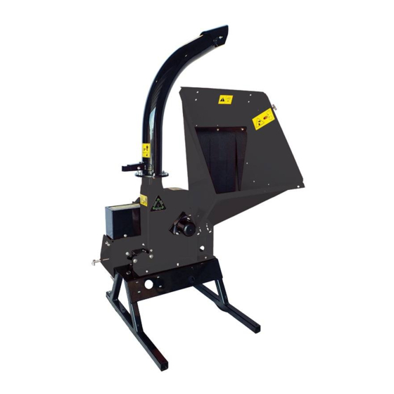
WOOD CHIPPER 9"
FOR
SKID STEER LOADERS
Do not use or operate this machine until this
manual has been read and understood.
Advertisement
Table of Contents

Subscribe to Our Youtube Channel
Related Manuals for Erskine Attachments WOOD CHIPPER 9

Summary of Contents for Erskine Attachments WOOD CHIPPER 9
- Page 1 Operator’s Manual Set-Up Assembly and Parts Information WOOD CHIPPER 9” SKID STEER LOADERS Do not use or operate this machine until this manual has been read and understood. Read the Operation & Maintenance Manual entirely. When you see this symbol, the subsequent instructions and warnings are serious – follow...
- Page 3 NOTE: Erskine Attachments LLC reserves the right to make improvements in design or changes in specifications at any time without notice and without incurring any obligations to install them on units previously sold.
- Page 4 REFERENCE INFORMATION Write the serial number for your attachment in the spaces below. Always refer to this serial number when calling for service or parts. Serial Number YOUR ATTACHMENT DEALER ADDRESS PHONE NUMBER CONTACT...
-
Page 5: Table Of Contents
TABLE OF CONTENTS 1 SAFETY ............................1 1.1 SAFETY ALERT SYMBOL .........................1 1.2 BEFORE OPERATING ..........................1 1.3 OPERATION SAFETY ..........................2 1.4 FEED ROLLER SAFETY ..........................2 1.5 MAINTENANCE/STORAGE SAFETY ......................2 1.6 SAFETY DECALS .............................3 1.7 SAFETY DECAL LOCATIONS ........................4 2 ASSEMBLY ............................5 2.1 ATTACH DISCHARGE TUBE ........................5 2.2 ATTACH CHIPPER CHUTE ........................6 2.3 MOUNTING THE FOUR-POSITION VALVE ....................7... -
Page 6: Safety
SAFETY 1.1 SAFETY ALERT SYMBOL The Owner/Operator’s manual uses this symbol to alert you WARNING of potential hazards. Whenever you see this symbol, read and obey the safety message that follows it. Failure to obey Indicates a potentially hazardous situation that, if not the safety message could result in personal injury, death or avoided, could result in death or serious injury. -
Page 7: Operation Safety
SAFETY 1.3 OPERATION SAFETY 1.4 FEED ROLLER SAFETY 1. Always stand clear of discharge area when operating 1. The feed roller can cause serious injury or death. Keep this machine. Keep face and body away from feed and hands, feet and clothing away from the feed roller and discharge openings. -
Page 8: Safety Decals
SAFETY 1.6 SAFETY DECALS The decals listed below correspond with the numbers in the Safety Decal Locations section. Familiarize yourself with all of the safety and operating decals on the machine and the associated hazards. See the engine owner’s manual or contact the engine manufacturer for engine safety instructions and decals. -
Page 9: Safety Decal Locations
SAFETY 1.7 SAFETY DECAL LOCATIONS The numbers below correspond to the decals listed in the Safety Decals section. Make certain that all safety and operating decals on this machine are kept clean and in good condition. Decals that need replacement must be applied to their original locations. -
Page 10: Assembly
ASSEMBLY WARNING If any bolts or nuts are dropped in the machine, be sure to remove them before starting the machine. 2.1 ATTACH DISCHARGE TUBE 1. Attach one clamping ring (1) and one spacer ring (2) to discharge tube base (3) using three 3/8" × 1-1/4" bolts (4) and nylock nuts (5). -
Page 11: Attach Chipper Chute
ASSEMBLY 7. Attach the discharge deflector (7) to the discharge tube. Connect the deflector with two 3/8" × 1-1/2" bolts (8) through the lower hole in the discharge tube. Run these bolts through the inside of the tube, 1/2" washer (12), deflector, 3/8" washer (13), and then knob (9). -
Page 12: Mounting The Four-Position Valve
ASSEMBLY MOUNTING CHUTE SUPPORT 1. Make sure the chute is mounted to the roller support weldment. 2. Place the chute support underneath the chute. 3. The side of the chute support with the two mounting holes is orientated towards the chipper base. 4. -
Page 13: Features & Controls
FEATURES & CONTROLS 3.1 STANDARD FEATURES & CONTROLS Understanding how your machine works will help you achieve the best results when using your chipper. The following descriptions define the features and controls of your machine. 1. CHUTE EXTENSION TRAY The feed chute has an extension tray that folds down. Raise the extension tray to an upright position and secure with latch before towing the machine. - Page 14 FEATURES & CONTROLS 9" SKID STEER CHIPPERS...
-
Page 15: Operation
OPERATION As with any other piece of outdoor equipment, getting the WARNING feel for how your machine operates and getting to know the best techniques for particular jobs are important to overall Move machine to a clear, level area outdoors before good performance. -
Page 16: Connecting Couplers
OPERATION 4.3 CONNECTING COUPLERS TO CONNECT WARNING 1. Before connecting, make sure to relieve the hydraulic pressure in the skid steer using the skid steer system. Hydraulic lines may be under pressure due to testing done at the factory. 2. Remove dirt and debris from the surface of the couplers. 3. -
Page 17: Pre-Operation
OPERATION 4.4 PRE-OPERATION 1. Wear appropriate eye, face, and hearing protection. Wear gloves that fit tight against the wrist. 2. Lower the chipper feed table. 3. Check that the feed roller is clear of material. 4. Place the feed roller control into the “stop” position. 5. -
Page 18: Chipper Operation Guidelines
OPERATION 4.7 CHIPPER OPERATION GUIDELINES WARNING WARNING Read and follow all safety instructions in this manual. To prevent personal injury or property damage: shut off Failure to operate the machine in accordance with the power source and make sure that all moving parts have safety instructions MAY RESULT IN PERSONAL INJURY! come to a complete stop before servicing, adjusting, or repairing machine. -
Page 19: Service & Maintenance
SERVICE & MAINTENANCE WARNING WARNING To prevent personal injury or property damage: shut off Chipping blades are sharp! Use caution when working on power source, disengage the hydraulics, open shield and machine to avoid injury. make sure that all moving parts have come to a complete stop before servicing, adjusting, or repairing machine. -
Page 20: Rotor Lock
SERVICE & MAINTENANCE WARNING BEFORE INSPECTING OR SERVICING ANY PART OF THIS MACHINE, SHUT OFF POWER SOURCE, DISCONNECT THE SPARK PLUG WIRE FROM THE SPARK PLUG, AND MAKE SURE ALL MOVING PARTS HAVE COME TO A COMPLETE STOP. 5.2 ROTOR LOCK WARNING The rotor assembly has a lock mechanism. -
Page 21: Chipper Blades Maintenance
SERVICE & MAINTENANCE WARNING BEFORE INSPECTING OR SERVICING ANY PART OF THIS MACHINE, SHUT OFF POWER SOURCE, DISCONNECT THE SPARK PLUG WIRE FROM THE SPARK PLUG, AND MAKE SURE ALL MOVING PARTS HAVE COME TO A COMPLETE STOP. 5.4 CHIPPER BLADES MAINTENANCE 5.5 REMOVING THE BLADES The chipper blades will eventually become dull, making The blades have two edges and can be reversed one time... -
Page 22: Sharpening The Blades
SERVICE & MAINTENANCE WARNING BEFORE INSPECTING OR SERVICING ANY PART OF THIS MACHINE, SHUT OFF POWER SOURCE, DISCONNECT THE SPARK PLUG WIRE FROM THE SPARK PLUG, AND MAKE SURE ALL MOVING PARTS HAVE COME TO A COMPLETE STOP. 5.6 SHARPENING THE BLADES The blades can be ground on a bench grinder or by a professional. -
Page 23: Chipper Blade Clearance
SERVICE & MAINTENANCE WARNING WARNING BEFORE INSPECTING OR SERVICING ANY PART OF THIS MACHINE, SHUT OFF POWER SOURCE, DISCONNECT THE SPARK BEFORE INSPECTING OR SERVICING ANY PART OF THIS MACHINE, SHUT OFF POWER SOURCE, DISCONNECT THE SPARK PLUG WIRE FROM THE SPARK PLUG, AND MAKE SURE ALL MOVING PARTS HAVE COME TO A COMPLETE STOP. PLUG WIRE FROM THE SPARK PLUG, AND MAKE SURE ALL MOVING PARTS HAVE COME TO A COMPLETE STOP. -
Page 24: Clearing A Plugged Rotor
SERVICE & MAINTENANCE WARNING BEFORE INSPECTING OR SERVICING ANY PART OF THIS MACHINE, SHUT OFF POWER SOURCE, DISCONNECT THE SPARK PLUG WIRE FROM THE SPARK PLUG, AND MAKE SURE ALL MOVING PARTS HAVE COME TO A COMPLETE STOP. 5.9 CLEARING A PLUGGED ROTOR Feeding too large or too much material at once may plug the chipper. -
Page 25: Lubrication
SERVICE & MAINTENANCE WARNING BEFORE INSPECTING OR SERVICING ANY PART OF THIS MACHINE, SHUT OFF POWER SOURCE, DISCONNECT THE SPARK PLUG WIRE FROM THE SPARK PLUG, AND MAKE SURE ALL MOVING PARTS HAVE COME TO A COMPLETE STOP. 5.10 LUBRICATION Lubricate the machine periodically with a lithium-based WARNING grease. -
Page 26: Troubleshooting
TROUBLESHOOTING Before performing any of the corrections in this troubleshooting chart, refer to the appropriate information contained in this manual for the correct safety precautions and operating or maintenance procedures. Contact your dealer for service problems with the machine. PROBLEM POSSIBLE CAUSES REMEDY Dull chipper blades... -
Page 27: Specifications
SPECIFICATIONS DESCRIPTION ENGLISH METRIC Machine Dimensions (L×W×H) 74" × 60" × 94" 188 cm × 152 cm × 239 cm Weight 1525 lbs. 692 kg Maximum Chipper Capacity 8" diameter 20.3 cm diameter Chipper Blades 4 reversible (5" × 4" × 0.5") 4 reversible (12.7 cm ×... -
Page 28: Bolt Torque
SPECIFICATIONS 7.1 BOLT TORQUE The tables below are for reference purposes only and their use by anyone is entirely voluntary, unless otherwise noted. Reliance on their content for any purpose is at the sole risk of that person and any loss or damage resulting from the use of this information is the responsibility of that person. - Page 29 This warranty may not be enlarged or modified in any manner except in writing signed by an executive officer of Erskine Attachments, LLC to improve its products whenever it is possible and practical to do so. Erskine Attachments, LLC reserves the right to make changes and or add improvements at any time without incurring any obligation to make such changes or add such improvements to products previously sold.
- Page 30 P/N 320634 Erskine Attachments LLC Printed in U.S.A. Erskine, MN 56535 Rev. A...
Need help?
Do you have a question about the WOOD CHIPPER 9 and is the answer not in the manual?
Questions and answers