
Related Manuals for ABLE BEKA BA504E


Summary of Contents for ABLE BEKA BA504E
- Page 1 Installation & Maintenance Instructions BA504E, BA524E Supplied by .com Call us on +44 (0)118 916 9420 | Email info@247able.com...
- Page 2 Reading Office Aberdeen Office Cutbush Park, Danehill, Lower Earley, Unit 6 Airside Business Park, Kirkhill Industrial Estate, Internet: www.able.co.uk Reading, Berkshire. RG6 4UT. UK. Dyce, Aberdeen. AB21 0GT. UK. e-procurement: www.247able.com Tel: +44 (0)118 9311188 Tel: +44 (0)1224 725999 Registered in England No: 01851002 Email: info@able.co.uk...
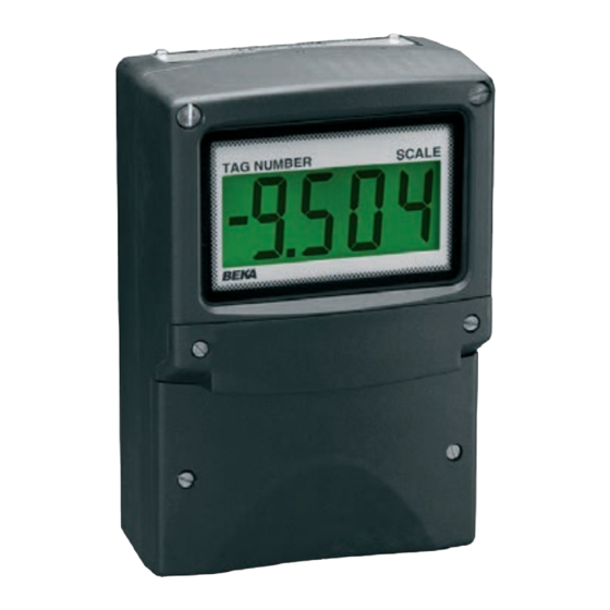
- Page 3 BA504E & BA524E General Purpose loop-powered field mounting indicators Issue 4 Issue: 4 March 2014...
-
Page 4: Table Of Contents
CONTENTS Description 7. Maintenance 7.1 Fault finding during commissioning Operation 7.2 Fault finding after commissioning 2.1 Controls 7.3 Servicing 7.4 Routine maintenance Applications 7.5 Guarantee 3.1 Transmitter loops 7.6 Customer comments 3.2 Remote indication 8. Accessories Installation 8.1 External keypad 4.1 Location 8.2 Units of measurement and instrument 4.2 Installation procedure... -
Page 5: Description
1. DESCRIPTION 2. OPERATION These field mounting, general purpose digital Fig 1 shows a simplified block diagram of both indicators display the current flowing in a 4/20mA models. The 4/20mA input current flows through loop in engineering units. They are loop powered resistor R1 and forward biased diode D1. -
Page 6: Controls
2.1 Controls 3. APPLICATIONS The indicators are controlled and calibrated via four push-button switches located behind the 3.1 Transmitter loops instrument control cover, or as an option on the Both models may be connected in series with any control cover. In the display mode i.e. -
Page 7: Installation
4.2 Installation Procedure illustrates instrument installation procedure. a. Remove the instrument terminal cover by unscrewing the two captive 'A' screws. b. Mount the instrument on a flat surface and secure with screws or bolts through the two 'B' holes. Alternatively use one of the pipe or stem mounting kits described in section 8.5. -
Page 8: Emc
Fig 5 Dimensions and terminal connections 4.3 EMC Both instruments compy with the requirements of the European EMC Directive 2004/108/EC. specified immunity all wiring should be in screened twisted pairs, with the screens connected at one point to the plants potential equalising conductor. -
Page 9: Configuration And Calibration
5.1 Summary of configuration functions 5. CONFIGURATION AND CALIBRATION Both indicators are configured and calibrated via This section summarises each of the main the four push buttons which are located behind the configuration functions and includes a cross control cover. All the configuration functions are reference to a more detailed description. -
Page 11: Resolution
5.2 Indicator function: ‘FunC’ Display Summary of function This configuration function defines the relationship 'C - - P' Function of P push-button between the indicator’s 4/20mA input current and The indicator may be configured to the indicator’s display. Three alternatives are display the input current in milliamps, or available: the input current as a percentage of the... -
Page 12: Calibration Using An External
5.6 Calibration using internal reference: ‘SEt’ 5.4 Position of the decimal point: ‘dP’ A dummy decimal point can be positioned between Using the ‘SEt’ function the indicator can be any of the digits or it may be absent. To position calibrated without the need to know the value of the decimal point select 'dP' from the menu and the 4/20mA input current, or to disconnect the... - Page 13 The indicator’s digital display at which the must be entered to gain access. New instruments bargraph starts is defined by the ‘bArLo’ sub- are configured with the default security code 0000 function which is selected by pressing the ▲ which allows unrestricted access...
-
Page 14: Current Source
6. LINEARISER level sensor in an irregular tank may be displayed A sixteen segment, seventeen breakpoint (0 to 16) in linear volumetric units by filling the tank with lineariser may be selected in the ‘FunC’ section of known incremental volumes and calibrating the the configuration menu. -
Page 16: Lineariser Calibration Using Internal Reference
When the required number of linearising break- 'dEL' Remove a break-point points have been entered, return Removes the displayed break-point linearisation sub-menu by pressing E. and joins the preceding segment to the indicator will display the 'Add' or 'dEL' prompt following segment with a straight line. -
Page 17: Lineariser Error Message
When the required number of linearising break- 6.4 Under and over-range point has been entered, return to the linearisation The lineariser does not change the under and sub-menu by pressing E. The indicator will display over-range indication described in section 6.12. the 'Add' or 'dEL' prompt depending upon the last At input currents below that specified for the first sub-function used. -
Page 18: Fault Finding During Commissioning
7. MAINTENANCE 7.3 Servicing All BA504E and BA524E loop powered indicators 7.1 Fault finding during commissioning are interchangeable if the required optional indicator fails function during backlight and alarms are fitted. A single spare commissioning the following procedure should be instrument may quickly be recalibrated to replace followed: any instrument that is damaged or fails. -
Page 19: External Keypad
8. ACCESSORIES 8.3 Alarms 8.1 External keypad CAUTION The four indicator push buttons are located behind These alarms outputs should not be used for critical safety applications such the instrument control cover, for applications emergency shut down system. requiring frequent adjustment an optional control cover fitted with an external keypad is available. -
Page 20: Solid State Output
8.3.1 Solid state output Each alarm has a galvanically isolated single pole solid state switch output which as shown in Fig 10. The output is polarised and current will only flow in one direction. less than 5Ω + 0.7V Roff greater than 1MΩ... -
Page 22: Configuration And Adjustment
8.3.2 Configuration and adjustment Summary of alarm configuration functions When optional alarms are fitted to a loop powered indicator the configuration menu is extended as Display Description of function shown in Fig 12. The additional functions appear between the ‘SEt’ and the ‘C- - P’ functions for the 'EnbL’... - Page 23 To check or change the alarm output status, select 8.3.3 Alarm enable: ‘EnbL’ This function allows each alarm to be enabled or 'no.nC' from the alarm configuration menu and disabled without altering any of the alarm press P to reveal the setting. The function may be parameters.
-
Page 24: Access Setpoint In Display
indicator is in the display mode is provided by a 8.3.9 Alarm silence time: SiL This function is primarily intended for use in small separate security code. installations where the alarm output directly operates an alarm annunciator such as a sounder This direct setpoint access menu is enabled and or beacon. -
Page 25: Displaying Setpoints On Ba524E Bargraph
8.3.13 Displaying setpoints on BA524E bargraph One of the selectable bargraph formats ‘AlrSP’ allows a low or a high setpoint plus the displayed value to be represented, or a low and a high setpoint plus the displayed value to be represented by the bargraph as shown in Fig 14. -
Page 26: Display Backlight
8.4 Display backlight 8.4.2 Separately powering the backlight The BA504E and BA524E loop powered indicators The optional backlight may also be powered from a can be supplied with a factory fitted backlight that separate power supply as shown in Fig 16. may be loop or separately powered. -
Page 27: Pipe Mounting Kits
8.5 Pipe mounting kits Two pipe mounting kits are available for securing the BA504E and BA524E to a horizontal or vertical pipe. BA392D Stainless steel bracket secured by two worm drive hose clips. Will clamp to any vertical or horizontal pipe with an outside diameter between 60 and 80mm.
Need help?
Do you have a question about the BEKA BA504E and is the answer not in the manual?
Questions and answers