Table of Contents
Advertisement
Quick Links
Installation & Maintenance Instructions
VEGAFLEX 66
4 ... 20 mA/HART - two-wire
Reading Office
Aberdeen Office
Cutbush Park, Danehill, Lower Earley,
Unit 6 Airside Business Park, Kirkhill Industrial Estate,
Reading, Berkshire. RG6 4UT. UK.
Dyce, Aberdeen. AB21 0GT. UK.
Tel: +44 (0)118 9311188
Tel: +44 (0)1224 725999
Email: info@able.co.uk
Email: ab@able.co.uk
Internet: www.able.co.uk
e-procurement: www.247able.com
Registered in England No: 01851002
VAT No: GB 417 2481 61
Advertisement
Table of Contents

Subscribe to Our Youtube Channel
Related Manuals for ABLE VEGA VEGAFLEX 66


Summary of Contents for ABLE VEGA VEGAFLEX 66
- Page 1 4 … 20 mA/HART - two-wire Reading Office Aberdeen Office Cutbush Park, Danehill, Lower Earley, Unit 6 Airside Business Park, Kirkhill Industrial Estate, Internet: www.able.co.uk Reading, Berkshire. RG6 4UT. UK. Dyce, Aberdeen. AB21 0GT. UK. e-procurement: www.247able.com Tel: +44 (0)118 9311188...
-
Page 2: Table Of Contents
Contents Contents About this document Function........Target group ......Symbolism used. - Page 3 Contents Maintenance and fault rectification Maintenance ......41 Rectify malfunctions ......41 Exchanging the electronics module .
-
Page 4: About This Document
1 About this document 1 About this document 1.1 Function This operating instructions manual provides all the information you need for mounting, connection and setup as well as important instructions for maintenance and fault rectification. Please read this information before putting the instrument into operation and keep this manual accessible in the immediate vicinity of the device. -
Page 5: For Your Safety
2 For your safety 2 For your safety 2.1 Authorised personnel All operations described in this operating instructions manual must be carried out only by trained specialist personnel authorised by the plant operator. During work on and with the device the required personal protective equipment must always be worn. -
Page 6: Safety Label On The Instrument
2 For your safety 2.5 Safety label on the instrument The safety approval markings and safety tips on the device must be observed. 2.6 CE conformity This device fulfills the legal requirements of the applicable EC guidelines. By attaching the CE mark, VEGA provides a confirmation of successful testing. -
Page 7: Product Description
3 Product description 3 Product description 3.1 Structure The scope of delivery encompasses: Scope of delivery VEGAFLEX 66 level sensor Documentation this operating instructions manual Safety Manual 31339 "VEGAFLEX series 60 - 4 … 20 mA/ HART" (optional) Operating instructions manual 27835 "Indicating and adjust- ment module PLICSCOM"... -
Page 8: Principle Of Operation
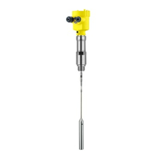
3 Product description Fig. 1: VEGAFLEX 66 in cable version with plastic housing Housing cover with integrated indicating and adjustment module (optional) Housing with electronics Process fitting The type label contains the most important data for identification and Type label use of the instrument: Article number Serial number... -
Page 9: Operation
3 Product description Two-wire electronics 4 … 20 mA/HART for power supply and Voltage supply measured value transmission over the same cable. The supply voltage range can differ depending on the instrument version. The data for power supply are specified in chapter "Technical data". The optional background lighting of the indicating and adjustment module is powered by the sensor. - Page 10 3 Product description Unless otherwise indicated, the packages must be stored only under the following conditions: Not in the open Dry and dust free Not exposed to corrosive media Protected against solar radiation Avoiding mechanical shock and vibration Storage and transport temperature see chapter "Supplement - Storage and transport temperature Technical data - Ambient conditions"...
-
Page 11: Mounting
4 Mounting 4 Mounting 4.1 General instructions Make sure that all parts of the instrument exposed to the process, in Suitability for the pro- particular the sensor element, process seal and process fitting, are cess conditions suitable for the existing process conditions. These include above all the process pressure, process temperature as well as the chemical properties of the medium. -
Page 12: Mounting Instructions
4 Mounting Fig. 2: Measures against moisture penetration The reference plane for the measuring range of the sensors is the Measuring range sealing surface of the thread or flange. Keep in mind that a min. distance must be maintained below the reference plane and possibly also at the end of the probe - measurement in these areas is not possible (dead band). - Page 13 4 Mounting keep in mind that measurement down to the tip of the probe is not possible. The exact value of the min. distance (lower dead band) is stated in chapter "Technical data". Fig. 3: Vessel with conical bottom Make sure that the probe is not subjected to strong lateral forces. Inflowing medium Mount VEGAFLEX 66 at a position in the vessel where no disturbances, e.g.
- Page 14 4 Mounting Excessive system vibration or shocks, e.g. caused by agitators or turbulence in the vessel (e.g. from fluidisation) can cause the coax probe of VEGAFLEX 66 to vibrate in resonance. Should a coax probe of more than 1 m (3.281 in) length should be used, you can provide a suitable support or guy directly above the end of the probe to stabilise Standpipes or bypass tubes are normally metal tubes with a diameter Standpipes or bypass...
- Page 15 4 Mounting Fig. 5: Position of the spacer Spacer Note: Measurement in a standpipe is not recommended for very adhesive products. If there is a danger of the probe touching the vessel wall during Fixing operation due to product movements or agitators etc., the measuring probe should be securely fixed.
- Page 16 4 Mounting Fig. 6: Vessel with temperature insulation Temperature insulation Ambient temperature on the housing VEGAFLEX 66 • 4 … 20 mA/HART two-wire...
-
Page 17: Connecting To Power Supply
5 Connecting to power supply 5 Connecting to power supply 5.1 Preparing the connection Always keep in mind the following safety instructions: Safety instructions Connect only in the complete absence of line voltage If overvoltage surges are expected, overvoltage arresters should be installed Tip: We recommend using VEGA overvoltage arresters B63-48 and... -
Page 18: Connection Procedure
5 Connecting to power supply Caution: No grease should be used when screwing the NPT cable gland or steel tube into the threaded insert. Standard grease can contain additives that corrode the connection between threaded insert and housing. This would influence the stability of the connection and the tightness of the housing. -
Page 19: Wiring Plan, Single Chamber Housing
5 Connecting to power supply Insert the wire ends into the open terminals according to the wiring plan Fig. 7: Connection steps 6 and 7 Press down the opening levers of the terminals, you will hear the terminal spring closing Check the hold of the wires in the terminals by lightly pulling on them 10 Connect the screen to the internal ground terminal, connect the... -
Page 20: Wiring Plan, Double Chamber Housing
5 Connecting to power supply Electronics and connec- tion compartment Display I ² C 5 6 7 8 Fig. 8: Electronics and connection compartment with single chamber housing Plug connector for VEGACONNECT (I²C interface) Spring-loaded terminals for connection of the external indication VEGADIS Ground terminal for connection of the cable screen Spring-loaded terminals for voltage supply Wiring plan... - Page 21 5 Connecting to power supply Electronics compart- ment Display I ² C 5 6 7 8 Fig. 10: Electronics compartment, double chamber housing Plug connector for VEGACONNECT (I²C interface) Internal connection cable to the connection compartment Terminals for VEGADIS 61 Connection compart- ment I ²...
-
Page 22: Wiring Plan With Double Chamber Housing Ex D
5 Connecting to power supply Wiring plan I 2 C Fig. 12: Wiring plan with double chamber housing Voltage supply/Signal output 5.5 Wiring plan with double chamber housing Ex d Electronics compart- ment Display I ² C 5 6 7 8 Fig. - Page 23 5 Connecting to power supply Connection compart- ment Fig. 14: Connection compartment with double chamber housing Ex d Spring-loaded terminals for power supply and cable screen Ground terminal for connection of the cable screen Wiring plan Fig. 15: Wiring plan with double chamber housing Ex d Voltage supply/Signal output VEGAFLEX 66 •...
-
Page 24: Wiring Plan - Version Ip 66/Ip 68, 1 Bar
5 Connecting to power supply 5.6 Wiring plan - version IP 66/IP 68, 1 bar Wire assignment con- nection cable Fig. 16: Wire assignment connection cable brown (+) and blue (-) to power supply or to the processing system Shielding VEGAFLEX 66 •... -
Page 25: Set Up With The Indicating And Adjustment Module Plicscom
6 Set up with the indicating and adjustment module PLICSCOM 6 Set up with the indicating and adjustment module PLICSCOM 6.1 Short description The indicating and adjustment module is used for measured value Function/Configuration display, adjustment and diagnosis. It can be mounted in the following housing versions and instruments: ®... - Page 26 6 Set up with the indicating and adjustment module PLICSCOM Fig. 17: Insert indicating and adjustment module Note: If you intend to retrofit the instrument with an indicating and adjustment module for continuous measured value indication, a higher cover with an inspection glass is required.
-
Page 27: Adjustment System
6 Set up with the indicating and adjustment module PLICSCOM 6.3 Adjustment system Fig. 18: Indicating and adjustment elements LC display Indication of the menu item number Adjustment keys [OK] key: Key functions Move to the menu overview Confirm selected menu Edit parameter Save value [->] key to select:... -
Page 28: Setup Steps
6 Set up with the indicating and adjustment module PLICSCOM 6.4 Setup steps After connecting VEGAFLEX 66 to power supply or after a voltage Switch on phase recurrence, the instrument carries out a self-check for approx. 30 seconds: Internal check of the electronics Indication of the instrument type, the firmware as well as the sensor TAGs (sensor designation) Output signal jumps briefly (approx. - Page 29 6 Set up with the indicating and adjustment module PLICSCOM Keep in mind that interfaces can cause faulty measurements. If you want to measure the total height of both liquids reliably, please contact our service department or use an instrument specially designed for interface measurement.
- Page 30 6 Set up with the indicating and adjustment module PLICSCOM Enter the appropriate distance value in m (corresponding to the percentage value) for the full vessel. Keep in mind that the max. level must lie below the dead band. Save the settings with [OK]. Each product has different reflective properties.
- Page 31 6 Set up with the indicating and adjustment module PLICSCOM A linearization is necessary for all vessels in which the vessel volume Linearisation curve does not increase linearly with the level - e.g. in a horizontal cylindrical or spherical tank - and the indication or output of the volume is required.
- Page 32 6 Set up with the indicating and adjustment module PLICSCOM Probes in coax version require no gating out of false echoes since they are not influenced by false reflections. Gating out of false signals Change now? Proceed as follows: Move from the measured value display to the main menu by pushing [OK].
- Page 33 6 Set up with the indicating and adjustment module PLICSCOM Gating out of false signals Copy sensor data Copy sensor data? Reset Basic adjustment If the function "Reset" is carried out, the sensor resets the values of the following menu items to the reset values (see chart): The following values will be reset: Function Reset value...
- Page 34 6 Set up with the indicating and adjustment module PLICSCOM Pointer The min. and max. values are reset to the actual value. Additional adjustment and diagnosis options such as e.g. scaling, Optional settings simulation or trend curve presentation are shown in the following menu schematic.
-
Page 35: Menu Schematic
6 Set up with the indicating and adjustment module PLICSCOM 6.5 Menu schematic Basic adjustment Basic adjustment ▶ Display Diagnostics Service Info Min. adjustment Max. adjustment Linearisation curve Damping 0.00 % 100.00 % linear 10.000 m(d) 1.000 m(d) 8.000 m(d) 2.000 m(d) Sensor-TAG Sensor... - Page 36 6 Set up with the indicating and adjustment module PLICSCOM Service Basic adjustment Display Diagnostics ▶ Service Info Gating out of false signals Current output Sensor Application ▼ ▼ Liquid Output mode: 4-20 mA ▼ ▼ 5.00 m(d) Change now? Failure mode: 20.5 mA ▼...
-
Page 37: Saving The Parameter Adjustment Data
6 Set up with the indicating and adjustment module PLICSCOM 6.6 Saving the parameter adjustment data It is recommended noting the adjusted data, e.g. in this operating instructions manual and archive them afterwards. They are hence available for multiple use or service purposes. If VEGAFLEX 66 is equipped with an indicating and adjustment module, the most important data can be read out of the sensor into indicating and adjustment module. -
Page 38: Connecting The Pc
7 Set up with PACTware and other adjustment programs 7 Set up with PACTware and other adjustment programs 7.1 Connecting the PC VEGACONNECT directly on the sensor Fig. 19: Connection of the PC via VEGACONNECT directly to the sensor USB cable to the PC VEGACONNECT Sensor VEGACONNECT exter-... -
Page 39: Parameter Adjustment With Pactware
7 Set up with PACTware and other adjustment programs Necessary components: VEGAFLEX 66 PC with PACTware and suitable VEGA DTM VEGACONNECT Power supply unit or processing system VEGACONNECT via HART Fig. 21: Connecting the PC via HART to the signal cable VEGAFLEX 66 HART resistance 250 Ω... -
Page 40: Parameter Adjustment With Ams™ And Pdm
7 Set up with PACTware and other adjustment programs Note: Keep in mind that for setup of VEGAFLEX 66, DTM-Collection in the actual version must be used. All currently available VEGA DTMs are included as a DTM Collection on a CD. They can be purchased for a token fee from the responsible VEGA agency. -
Page 41: Maintenance And Fault Rectification
8 Maintenance and fault rectification 8 Maintenance and fault rectification 8.1 Maintenance When used as directed in normal operation, VEGAFLEX 66 is completely maintenance free. 8.2 Rectify malfunctions The operator of the system is responsible for taking suitable measures Reaction when malfunc- to remove interferences. - Page 42 8 Maintenance and fault rectification Error Cause Removal Voltage supply Check cables for breaks; repair if missing necessary Operating voltage Check, adapt if necessary too low or load resistance too high Current signal Oscillator in the Exchange the instrument or send it in greater than 22 mA sensor defective for repair...
-
Page 43: Exchanging The Electronics Module
8 Maintenance and fault rectification 8.3 Exchanging the electronics module If the electronics module is defective, it can be replaced by the user. In Ex applications only one instrument and one electronics module with respective Ex approval may be used. If there is no electronics module available on site, one can be ordered from the VEGA agency serving you. -
Page 44: Instrument Repair
8 Maintenance and fault rectification At "www.vega.com/downloads" go to "Software". Select under "plics Load sensor software to instruments and sensors" the suitable instrument series. Load the zip file via the right mouse key with "Save target as" e.g. on the desktop of your PC. -
Page 45: Dismounting
9 Dismounting 9 Dismounting 9.1 Dismounting steps Warning: Before dismounting, be aware of dangerous process conditions such as e.g. pressure in the vessel, high temperatures, corrosive or toxic products etc. Take note of chapters "Mounting" and "Connecting to power supply" and carry out the listed steps in reverse order. -
Page 46: Supplement
10 Supplement 10 Supplement 10.1 Technical data General data Material 316L corresponds to 1.4404 or 1.4435 Materials, wetted parts Process fitting - coax version 316L and PEEK GF30, Hastelloy C22 (2.4602) and PEEK GF30 Process fitting - rod version 316L and PEEK GF30, Hastelloy C22 (2.4602) and PEEK GF30 Process fitting - cable version 316L and PEEK GF30... - Page 47 10 Supplement Rod: ø 6 mm (0.236 in) approx. 220 g/m (2.365 oz/ft) Cable: ø 2 mm (0.079 in) approx. 20 g/m (0.215 oz/ft) Cable: ø 4 mm (0.157 in) approx. 80 g/m (0.86 oz/ft) Gravity weight approx. 325 g (11.5 oz) Probe length L (from seal surface) Tube: ø...
- Page 48 10 Supplement Fig. 22: Measuring range of VEGAFLEX 66 - coax version Reference plane Probe length Measuring range Upper dead band (see diagrams under Accuracy - grey section) Lower dead band (see diagrams under Accuracy - grey section) Min. dielectric figure of the medium - rod, >...
- Page 49 10 Supplement Fig. 23: Measuring ranges of the VEGAFLEX 66 - rod and cable version Reference plane Probe length Measuring range (default setting refers to the measuring range in water) Upper dead band (see diagrams under Accuracy - grey section) Lower dead band (see diagrams under Accuracy - grey section) Output variable Output signal...
- Page 50 10 Supplement 2. HART value (Secondary Value) Distance to the level - scaled (for example hl, %) Resolution, digital > 1 mm (0.039 in) Accuracy (similar to DIN EN 60770-1) Process reference conditions according to DIN EN 61298-1 Temperature +18 … +30 °C (+64 … +86 °F) Relative humidity 45 …...
- Page 51 10 Supplement 15 mm (0.591 " 3 mm (0.118 ") -3 mm (-0.118 ") -10 mm (-0.394 ") 0,08 m 0,25 m 0,02 m (3.15 (9.843 " " (0.787 ") Fig. 24: Deviation VEGAFLEX 66 in rod version in water Dead zone - no measurement possible in this area Probe length 10 mm...
- Page 52 10 Supplement 15 mm (0.591 " 3 mm (0.118 ") -3 mm (-0.118 ") -15 mm (-0.591 ") 0,08 m 0,25 m 0,25 m (3.149 " (9.843 " (9.843 ") Fig. 26: Deviation VEGAFLEX 66 in cable version, probe length L < 20 m in water Dead zone - no measurement possible in this area Probe length 10 mm...
- Page 53 10 Supplement 5 mm (0.197 ") 3 mm (0.118 ") -3 mm (-0.118 ") -50 mm (1.969 ") 0,02 m 0,03 m (1.181 " 0,15 m (5.906 " (0.787 ") Fig. 28: Deviation VEGAFLEX 66 in coax version in water Dead zone - no measurement possible in this area Probe length 10 mm (0.394...
- Page 54 10 Supplement Process conditions Process pressure -1 … +100 bar/-100 … +10000 kPa (- -14.5 … +1450 psig), depending on the process fitting Process temperature -20 … +250 °C (-4 … +482 °F) The measurement error from the process condi- tions is in the specified pressure and temperature range of below 1 %.
- Page 55 10 Supplement 1 x closing cap ½ NPT, 1 x blind stopper ½ NPT, 1 x blind stopper M16 x 1.5 or optionally 1 x plug M12 x 1 for VEGADIS 61 1 x plug (depending on the version), 1 x blind stopper M20 x 1.5;...
- Page 56 10 Supplement Voltage supply Operating voltage Non-Ex instrument 14 … 36 V DC EEx-ia instrument 14 … 30 V DC EEx-d-ia instrument 20 … 36 V DC Operating voltage with lighted indicating and adjustment module Non-Ex instrument 20 … 36 V DC EEx-ia instrument 20 …...
- Page 57 10 Supplement Protection class Functional safety (SIL) Functional safety is already activated on instruments with SIL qualification ex factory. On instruments without SIL qualification ex factory, the functional safety must be activated by the user via the indicating and adjustment module or via PACTware for applications according to SIL. Functional safety according to IEC 61508-4 Single channel architecture (1oo1D) up to SIL2...
-
Page 58: Dimensions
10 Supplement 10.2 Dimensions The following dimensional drawings represent only an extract of the possible versions. Detailed dimensional drawings can be downloaded on www.vega.com under "Downloads" and "Drawings". Plastic housing ~ 69 mm ~ 87 mm (3.43") (2.72") ø 84 mm ø... - Page 59 10 Supplement Aluminium housing in protection rating IP 66/IP 68, 1 bar ~ 105 mm (4.13") ~ 150 mm (5.91") ø 84 mm ø 84 mm (3.31") (3.31") M16x1,5 M20x1,5 M20x1,5 M20x1,5/ ½ NPT Single chamber version Double chamber version Stainless steel housing ~ 69 mm ~ 59 mm...
- Page 60 10 Supplement VEGAFLEX 66 - cable, rod version (-20 … +250 °C/-4 … +482 °F) SW41 (G1 / 1 NPT) SW46 (G1½ / 1½ NPT) G1 / 1 NPT, G1½ / 1½ NPT ø 2 mm / ø 4 mm (0.08") (0.16") ø...
- Page 61 10 Supplement VEGAFLEX 66 - coax version (-20 … +250 °C/-4 … +482 °F) SW 36 (1.42") (G¾, ¾ NPT) SW 41 (1.61") (G1, 1 NPT) SW 46 (1.81") (G1½, 1½ NPT) G¾ / ¾ NPT, G1 / 1 NPT, G1½...
- Page 62 10 Supplement 10.3 Industrial property rights VEGA product lines are global protected by industrial property rights. Further information see http://www.vega.com Only in U.S.A.: Further information see patent label at the sensor housing. VEGA Produktfamilien sind weltweit geschützt durch gewerbliche Schutzrechte. Nähere Informationen unter http://www.vega.com Les lignes de produits VEGA sont globalement protégées par des...
- Page 63 10 Supplement VEGAFLEX 66 • 4 … 20 mA/HART two-wire...
- Page 64 All statements concerning scope of delivery, application, practical use and operating conditions of the sensors and processing systems correspond to the information avail- able at the time of printing. © VEGA Grieshaber KG, Schiltach/Germany 2010 Subject to change without prior notice...
Need help?
Do you have a question about the VEGA VEGAFLEX 66 and is the answer not in the manual?
Questions and answers