Table of Contents
Advertisement
Quick Links
Installation and operating instructions for the
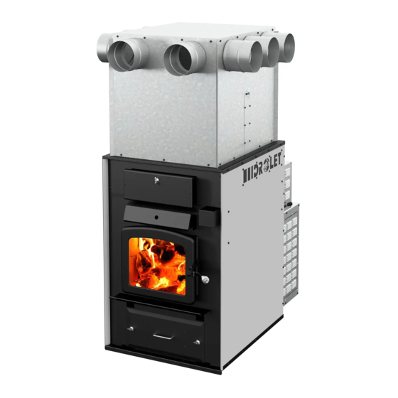
TUNDRA II WOOD FURNACE
(
model)
DF02001
Verified and tested for Canada
and the United States
by an accredited laboratory
Stove Builder International Inc.
250, rue de Copenhague,
St-Augustin-de-Desmaures (Quebec)
Canada G3A 2H3
After-sale service: 418-908-8002
E-mail: tech@sbi-international.com
This manual is available for free download on the manufacturer's web site. It is a copyrighted
document. Re-sale is strictly prohibited. The manufacturer may update this manual from time
to time and cannot be responsible for problems, injuries, or damages arising out of the use of
information contained in any manual obtained from unauthorized sources.
Please keep this document!
READ THESE INSTRUCTIONS CAREFULLY BEFORE INSTALLING AND
OPERATING YOUR FURNACE.
PLEASE KEEP THIS MANUAL FOR REFERENCE
45846A
Printed in Canada
19-03-2019
Advertisement
Table of Contents
Troubleshooting

Related Manuals for Drolet TUNDRA II


Summary of Contents for Drolet TUNDRA II
- Page 1 Installation and operating instructions for the TUNDRA II WOOD FURNACE model) DF02001 Verified and tested for Canada and the United States by an accredited laboratory Stove Builder International Inc. 250, rue de Copenhague, St-Augustin-de-Desmaures (Quebec) Canada G3A 2H3 After-sale service: 418-908-8002 E-mail: tech@sbi-international.com...
- Page 2 Tundra II Furnace Installation and Operation Manual THANK YOU FOR CHOOSING THIS DROLET WOOD FURNACE As one of North America’s largest and most respected wood stove, furnace and fireplace manufacturers, Stove Builder International takes pride in the quality and performance of all its products.
-
Page 3: Table Of Contents
Tundra II Furnace Installation and Operation Manual Table of contents PART 1 – INSTALLATION ................6 INTRODUCTION ....................6 1 Regulations and safety warnings covering installation .......7 1.1 Regulations covering furnace installation ..............7 1.2 Cautions and warnings covering installation ............... 7 2 Authorized and non-authorized configuration ........8... - Page 4 Tundra II Furnace Installation and Operation Manual 5.4.1 Start-off plenum ....................25 5.4.2 Installing the start-off adapters ................26 5.4.3 Minimum amount of outlets and maximum lengths of ducts ......... 26 5.5 Air return system and filter ..................28 6 Combustion air ..................29 7 Electrical connection, adjustment of components and calibration of the draw ....................
- Page 5 10.1 Installation of secondary air tubes and baffle ............61 11 Exploded diagram and parts list ............63 PART 3 – FEATURES AND SAFETY ............70 12 General information on Tundra II (DF02001) ........71 12.1 Appliance performance ..................71 12.2 General Features ......................
-
Page 6: Part 1 - Installation
Tundra II Furnace Installation and Operation Manual PART 1 – INSTALLATION Please see Part 2 for operation, maintenance and troubleshooting instructions. Please see Part 3 for features and safety instructions. INTRODUCTION This furnace uses the same wood burning technology as a high efficiency certified CSA B415.1-10. -
Page 7: Regulations And Safety Warnings Covering Installation
Tundra II Furnace Installation and Operation Manual 1 Regulations and safety warnings covering installation 1.1 Regulations covering furnace installation CAUTION FOLLOW LOCAL CODES (IF IN DOUBT, CONTACT YOUR LOCAL HEATING APPLIANCE RETAILER, YOUR MUNICIPALITY OR YOUR FIRE DEPARTMENT. Installation must be made in accordance with the following standards;... -
Page 8: Authorized And Non-Authorized Configuration
Tundra II Furnace Installation and Operation Manual 2 Authorized and non-authorized configuration 2.1 Authorized configurations in Canada and United States The wood furnace is the only appliance connected to the hot air distribution duct system and air return duct system. -
Page 9: Non-Authorized Configuration, Canada And United States
Tundra II Furnace Installation and Operation Manual 2.3 Non-authorized configuration, Canada and United States The hot air duct (A) must not be installed in the air return of (B). The hot air duct (B) must not be installed in the air return of (A). -
Page 10: Clearances To Combustible Material
Tundra II Furnace Installation and Operation Manual 3.3 Clearances to combustible material The clearances shown in this section have been determined by safety tests under normal and even abnormal operating conditions according to procedures set out in standards CSA B366.1 (Canada) and UL 391 (U.S.A.). Respecting the minimum clearances is mandatory... -
Page 11: Clearances With Single And Double Wall Pipe
Tundra II Furnace Installation and Operation Manual Clearances with single and double wall pipe 3.3.1 CANADA 16" (406 mm) (from the back 16" (406 mm) (from the back of of the blower box) the blower box) 18" (457 mm) 18" (457 mm) 5"... -
Page 12: Floor Protection
Tundra II Furnace Installation and Operation Manual 3.3.3 Floor protection If the floor is made of non combustible material, no floor protector is required. If the floor is made of combustible material, a floor protector is required (see table below). -
Page 13: The Venting System
Tundra II Furnace Installation and Operation Manual 4 The venting system WARNING: DO NOT INSTALL A MANUAL DAMPER ON THIS FURNACE. CAUTION: BEFORE THE CONNECTOR PIPES ARE INSTALLED, MAKE SURE THAT THE EXHAUST PIPE AND / OR THE EXCHANGERS OF THE FURNACE ARE FREE OF ALL ITEMS. -
Page 14: Masonry Chimneys
Tundra II Furnace Installation and Operation Manual Good system design Inferior system design Inside chimneys are preferred because Outside chimneys are a problem because even when no fire is burning, there is when no fire burns they will go into cold normally upward flow in the system. -
Page 15: Minimum Chimney Height
Tundra II Furnace Installation and Operation Manual 4.1.3 Minimum chimney height The top of the chimney should be tall enough to be above the air turbulence caused when wind blows against the house and its roof. chimney must extend at least 3 ft. - Page 16 Tundra II Furnace Installation and Operation Manual CAUSES RESTRICTION Proper installation improper installation o Maximum unsupported horizontal length: 3 feet (1 m); o Galvanized flue pipes must not be used because the coatings vaporize at high temperatures and release dangerous gases;...
-
Page 17: Hot Air Distribution And Air Return System
Alternative installations with 90° elbow or tee. 5 Hot air distribution and air return system The Drolet furnace is designed and equipped with a hot air distribution plenum that may receive 6 to 10, 6" (152 mm) diameter round ducts. -
Page 18: Hot Air Distribution Plenum Height According To Ceiling Height
Tundra II Furnace Installation and Operation Manual N.B.: The furnace air jacket is not totally air tight. It is normal to detect some air leaks at the jacket’s joints. Components provided with the furnace: 10 hot air start-off 4 lids (B) -
Page 19: Adjustable Height Of The Plenum; (With The Plenum Extension Cut Off (A))
Tundra II Furnace Installation and Operation Manual 5.1.2 Adjustable height of the plenum; (with the plenum extension cut off (A)). When the ceiling height, measured from the floor is greater than 72" (183 cm), but less than 84" (213 cm), it will be possible to cut the plenum extension (A) of at most 8"... -
Page 20: Assembling The Hot Air Distribution Plenum (A And B)
Tundra II Furnace Installation and Operation Manual 5.2 Assembling the hot air distribution plenum (A and B). 5.2.1 Assembling the plenum extension (A) by means of 12 screws and corner reinforcements... -
Page 21: Assembling The Plenum (B)
Tundra II Furnace Installation and Operation Manual 5.2.2 Assembling the plenum (B) Insert the male end of each panel in the female part of the adjacent panel. Secure the assembly by bending the two metal tabs in the center of each corner. - Page 22 Tundra II Furnace Installation and Operation Manual Install the cover on the part (B) of the assembly and secure it with 16 screws.
-
Page 23: Assembling The Plenum Extension (A) To The Plenum (B)
Tundra II Furnace Installation and Operation Manual 5.2.3 Assembling the plenum extension (A) to the plenum (B) Slide plenum (B) over the plenum extension (A) to the extent determined in Section 5.1. Using 13 self-drilling screws, secure plenum plenum extension (A). -
Page 24: Installation Of The Assembled Plenum On The Furnace
Tundra II Furnace Installation and Operation Manual 5.3 Installation of the assembled plenum on the furnace Identify the right side of the plenum, it is provided with holes for the installation of the “RTD” thermal probe. Also, 5 holes are aligned with the fold of the top of the furnace on the right side and three holes on the other sides. -
Page 25: Configuration And Restrictions Of Hot Air Distribution System
Tundra II Furnace Installation and Operation Manual 5.4 Configuration and restrictions of hot air distribution system 5.4.1 Start-off plenum The plenum can be adjusted from 64" (163 cm) to 88" (224 cm) depending on ceiling height. See Section 5.1: Hot air distribution plenum height according to ceiling height. -
Page 26: Installing The Start-Off Adapters
Tundra II Furnace Installation and Operation Manual 5.4.2 Installing the start-off adapters After choosing your output configuration, do the following to install the start-off adapters. Warning: Use gloves to complete the following steps because the start-off adapters and caps can be sharp. - Page 27 Tundra II Furnace Installation and Operation Manual Block the unused outlets with the block-off caps (B) and provided screws (D). FAVOR THE USE RIGID DUCTS BECAUSE THERE ARE LESS RESTRICTIVE TO AIR FLOW. The maximum run of a main duct is 35’ (10.7 m). It must be reduced from 6" (152 mm) to 5"...
-
Page 28: Air Return System And Filter
Tundra II Furnace Installation and Operation Manual The total area of secondary duct outlets must be equal or slightly less than the total area of the outlets used on the distribution plenum (B). Example of surface calculation according to the number... -
Page 29: Combustion Air
Additional combustion air can be provided following the following methods, provided that they satisfy chapter 4 of the CSA B365 standard for Canada: Direct combustion air supply: o The Tundra II is not certified to be connected directly to a new combustion air supply. Indirect combustion air supply: o New combustion air can be brought into a pipe located within approximately 12"... - Page 30 Tundra II Furnace Installation and Operation Manual...
-
Page 31: Installation And Connection Of The "Rtd" Thermal Probe
Tundra II Furnace Installation and Operation Manual 7.2 Installation and connection of the “RTD” thermal probe IMPORTANT: The proper positioning of the “RTD” thermal probe is essential to the proper functioning of the furnace. Install it in the opening provided for this purpose on the start-off plenum. - Page 32 Tundra II Furnace Installation and Operation Manual With plenum (B) only Using self-drilling screws (D), install the plate supplied with the furnace on the plenum (B). Make sure to have the notch on the plate up. Install the RTD probe in the hole of the plenum (B).
-
Page 33: Blower Technical Data
Tundra II Furnace Installation and Operation Manual NOTE IT IS POSSIBLE TO SEE THE TEMPERATURE READ BY THE RTD BY PRESSING THE LEFT BUTTON ON THE DIGITAL DISPLAY AT THE BACK OF THE FURNACE. 7.3 Blower technical Data The blower speed must conform to the recommendations of the Warm Air Heating and Air Conditioning National Association and should respect the static pressure ranges in the warm air plenum of the furnace. -
Page 34: Draw Calibration
Tundra II Furnace Installation and Operation Manual Draw Calibration The draw: The measurement is taken in the exhaust pipe 18" (457 mm) above the furnace's flue collar with a tube and a pressure gauge (manometer). Poor: -0.03" W.C. (7.5 Pa) and under: ignition problems, risk of smoke spillage, low performance of heat exchangers. -
Page 35: Appendix 1: Optional Thermostat Installation
Tundra II Furnace Installation and Operation Manual Appendix 1: Optional thermostat installation Using a thermostat will help you maintain a constant temperature throughout the house. A fixed wall mounted 24v thermostat is required. Note: Thermostat manufacturer’s instruction always overrides the information published in the following section. - Page 36 Tundra II Furnace Installation and Operation Manual Example of thermostat wiring: Connect one wire to "RH" and the other wire to "W". The red jumper can be left in place. For more information, refer to the manufacturer's instructions. This furnace may be installed in parallel as an add-on to an existing furnace in the USA only.
- Page 37 Tundra II Furnace Installation and Operation Manual 2- From the thermostat connected to the existing furnace, connect 2 new wire (B) on the R and W terminals of your thermostat and fix them to the terminal on the circuit board labeled "I"...
-
Page 38: Appendix 2: Optional Air Filters (Ac01390, Ac01391)
Tundra II Furnace Installation and Operation Manual Appendix 2: Optional air filters (AC01390, AC01391) The filter option (AC01390 – cardboard frame or AC01391 – washable aluminum) allows filtrating dirt before distribution warm air in your installation in addition of protecting your blower. -
Page 39: Appendix 3: Optional Fresh Air Return Adapter (Ac01392)
Tundra II Furnace Installation and Operation Manual Appendix 3: Optional Fresh air return adapter (AC01392) The optional air return adapter (AC01392) can be added to the furnace blower box to increase the efficiency of your system. This option allows you to take in the fresh air from the rooms connected to the return system and bring it back towards the furnace to be heated. -
Page 40: Part 2 -Operation, Maintenance And Troubleshooting
Tundra II Furnace Installation and Operation Manual PART 2 – OPERATION, MAINTENANCE AND TROUBLESHOOTING Please see Part 1 for installation instructions. Please see Part 3 for features and safety instructions. 7.5 How to prepare or buy good firewood 7.5.1 What is good firewood? Good firewood has been cut to the correct length for the furnace, split to a range of sizes and stacked in the open until its moisture content is reduced to 15 to 20 per cent. -
Page 41: Piece Size
Tundra II Furnace Installation and Operation Manual 7.5.4 Piece size Firewood dries more quickly when it is split. Large unsplit rounds can take years to dry enough to burn. Even when dried, unsplit logs are difficult to ignite because they don’t have the sharp edges where the flames first catch. -
Page 42: Judging Firewood Moisture Content
Tundra II Furnace Installation and Operation Manual Here are some things to consider in estimating drying time: firewood takes a long time to dry • firewood bought from a dealer is rarely dry enough to burn, so it is advisable to buy the •... -
Page 43: Operating Your Furnace
Tundra II Furnace Installation and Operation Manual 8 Operating your furnace 8.1 Your first fires Two things will happen as you burn your first few fires; the paint cures and the internal components of the furnace are conditioned. As the paint cures, some of the chemicals vaporize. The vapours are not poisonous, but they do smell bad. -
Page 44: The Top Down Fire
Tundra II Furnace Installation and Operation Manual 8.2.2 The top down fire The top down fire starting method solves two problems with the conventional method: first, it does not collapse and smother itself as it burns; and second, it is not necessary to build up the fire gradually because the firebox is loaded before the fire is lit. -
Page 45: Raking Charcoal
Tundra II Furnace Installation and Operation Manual When you burn in cycles, you rarely need to open the furnace’s loading door while the wood is burning. This is an advantage because there is more chance that smoke will leak from the furnace when the door is opened as a full fire is burning. This is especially true if the chimney connector has 90 degree elbows and if the chimney runs up the outside wall of the house. -
Page 46: Firing Each New Hot Load
Tundra II Furnace Installation and Operation Manual 8.3.3 Firing each new hot load Place the new load of wood on and behind the charcoal, and not too close to the glass. Close the door and open the air control fully. Leave the air control fully open until the firebox is full of flames, the wood has charred to black and its edges are glowing red. -
Page 47: Building Different Fires For Different Needs
Tundra II Furnace Installation and Operation Manual The following figure shows the position of the air inlet damper (A) according to the position of the air inlet damper switch (B). DETAIL B DETAIL A 8.3.5 Building different fires for different needs Using the air control is not the only way to match the furnace’s heat output to the heat... -
Page 48: Control Of The Air Inlet Damper
Tundra II Furnace Installation and Operation Manual 8.3.5.3 High output fires for cold weather When the heat demand is high during cold weather, you’ll need a fire that burns steadily and brightly. This is the time to use your biggest pieces of hardwood fuel if you have it. Put the biggest pieces at the back of the firebox and place the rest of the pieces compactly. -
Page 49: Additional Fresh Air Supply
Tundra II Furnace Installation and Operation Manual Reducing the combustion air will do two things. First, the combustion rate will decrease, which will spread the thermal energy of the fuel over a longer period of time. In addition, the velocity of the exhaust gas decreases, which allows better heat transfer in the heat exchanger and chimney. -
Page 50: Manual Or Thermostat Control
Tundra II Furnace Installation and Operation Manual 8.5 Manual or thermostat control From factory, the opening and closing of the air inlet damper is manually activated by the means of a switch located at the rear of the furnace. The switch has two positions; opened and closed. -
Page 51: Maintaining Your Wood Heating System
Tundra II Furnace Installation and Operation Manual 9 Maintaining your wood heating system 9.1 Furnace maintenance Your new furnace will give many years of reliable service if you use and maintain it correctly. Some of the internal components of the firebox, such as firebricks, baffles and air tubes, will wear over time under intense heat. -
Page 52: Door Adjustment
Tundra II Furnace Installation and Operation Manual If you do get brown stains on the glass you can remove them with special cleaners for wood furnace glass doors. Do not use abrasives to clean your furnace’s door glass. The deposits that form on the glass are the best indication of the quality of your fuel and how well you are doing in operating the furnace. -
Page 53: Replacement Of The Glass And Gaskets
Tundra II Furnace Installation and Operation Manual 9.1.4 Replacement of the glass and gaskets After a year or more of use, the gasket of the door will compress and become hard which can allow air to pass. You can check the air tightness of your door gasket by closing and locking the door on a piece of paper. -
Page 54: Cleaning And Painting The Furnace
Tundra II Furnace Installation and Operation Manual 9. Install the glass (E) and glass frame (D) centering them in the door frame. Install the glass retainers (C) taking care not to over tighten the screws (B). Note that the two main causes of glass breakage are unequal position in the door and screws too tight. -
Page 55: Heat Exchangers Care
Tundra II Furnace Installation and Operation Manual 9.1.6 Heat exchangers care Heat exchangers must be cleaned thoroughly at the end of every heating season. During summer, the air in basements is damper and with minimal air circulation within the furnace, it can mix with creosote and/or sooth deposits in the exchangers to form an acid that could accelerate the corrosion process and induce premature decay of the steel. - Page 56 Tundra II Furnace Installation and Operation Manual 2. Move the baffle of the combustion chamber forward. 3. Use the tool provided, clean the three exchanger pipes.
- Page 57 Tundra II Furnace Installation and Operation Manual 4. Dirt in the lateral exchangers (1 and 3) fall into the combustion chamber at the rear. 5. Dirt in the central exchanger (2) will be removed from the front or the rear of the furnace.
-
Page 58: Chimney And Chimney Connector Maintenance
Tundra II Furnace Installation and Operation Manual 7. Close the exchanger access door and secure it using the washer (C) and wing nut (B). 8. If you have performed maintenance from the back part of the furnace, reinstall the black pipe connector and secure it with three screws. -
Page 59: Cleaning The Chimney
Tundra II Furnace Installation and Operation Manual 9.2.3 Cleaning the chimney Chimney cleaning can be a difficult and dangerous job. If you don’t have experience cleaning chimneys, you might want to hire a professional chimney sweep to clean and inspect the system for the first time. After having seen the cleaning process, you can decide if it is a job you would like to take on. -
Page 60: Troubleshooting
Tundra II Furnace Installation and Operation Manual 10 Troubleshooting PROBLEM CAUSES SOLUTIONS Heating inefficient during the Improper adjustment of the Adjust the damper, minimize first combustions. Lack of barometric damper (opened the smoke pipe length and use draft. too wide). Chimney flue elbows. -
Page 61: Installation Of Secondary Air Tubes And Baffle
Tundra II Furnace Installation and Operation Manual 10.1 Installation of secondary air tubes and baffle 1- Starting with the rear tube, lean and insert the right end of the secondary air tube into the rear right channel hole. Then lift and insert the left end of the tube into the rear left channel. - Page 62 Tundra II Furnace Installation and Operation Manual Note that secondary air tubes (A) can be replaced without removing the baffle board (B). Important Notes: The air tubes are identified for placement as follows: Model Type of tube TUNDRA II Front (1) ► 106 holes of 0.109"...
-
Page 63: Exploded Diagram And Parts List
Tundra II Furnace Installation and Operation Manual 11 Exploded diagram and parts list... - Page 64 Tundra II Furnace Installation and Operation Manual...
- Page 65 Tundra II Furnace Installation and Operation Manual...
- Page 66 Tundra II Furnace Installation and Operation Manual...
- Page 67 Tundra II Furnace Installation and Operation Manual...
- Page 68 Tundra II Furnace Installation and Operation Manual IMPORTANT: THIS IS DATED INFORMATION. When requesting service or replacement parts for your furnace, please provide the model and the serial number. We reserve the right to change parts due to technology upgrade or availability. Contact an authorized dealer to obtain any of these parts.
- Page 69 Tundra II Furnace Installation and Operation Manual ITEM DESCRIPTION AC06810 SELF ADHESIVE BLACK GASKET KIT 1/8" X 3/8" X 6' AC06725 GLUE AND 3/4" X 7' WHITE DOOR GASKET KIT PL51349 GLASS RETAINER FRAME 30416 WING NUT 3/8"-16 28061 CHROME ASH DRAWER HANDLE...
-
Page 70: Part 3 - Features And Safety
Tundra II Furnace Installation and Operation Manual ITEM DESCRIPTION 51009 1/4 HP DD-4 SPEED MOTOR 1075/4RPM 30094 HEX SCREW WASHER HEAD 1/4-20 X 3/4" F ZINC TYPE PL66043 BLOWER BOX SURROUND PL66042 BLOWER BOX TOP AC01390 CARDBOARD FRAME AIR FILTER WITH SUPPORT (20" X 15" X 1") 21044 CARDBOARD FRAME AIR FILTER 20"... -
Page 71: General Information On Tundra Ii (Df02001)
Tundra II Furnace Installation and Operation Manual 12 General information on Tundra II (DF02001) 12.1 Appliance performance Fuel type Dry cordwood Recommended heating area 1,000 to 2,500 ft² (93 à 232 m²) Firebox volume 3.6 ft³ (0.102 m³) Maximum burn time... -
Page 72: General Features
Tundra II Furnace Installation and Operation Manual 12.2 General Features Maximum log length 21" (533 mm) north-south** Diameter of the flue collar 6 in. (152 mm) Recommended connector pipe diameter 6 in. (152 mm) Recommended chimney diameter 6 in. (152 mm) Required type of chimney CAN/ULC S629, UL 103 HT (2100 °F) -
Page 73: Technical Data Tundra Ii
Tundra II Furnace Installation and Operation Manual 12.2.1 Technical data Tundra II... - Page 74 Tundra II Furnace Installation and Operation Manual...
-
Page 75: The Benefits Of Low Emissions And High Efficiency
Tundra II Furnace Installation and Operation Manual 12.3 The benefits of low emissions and high efficiency The low smoke emissions produced by the special features inside the Brand Model firebox mean that your household will release up to 90 percent less smoke into the outside environment than if you used an older conventional wood furnace. -
Page 76: Safety Information
Tundra II Furnace Installation and Operation Manual 13 Safety information 13.1 Cautions and warnings • A CARBON MONOXIDE (CO) DETECTOR/ALARM IS REQUIRED IN THE ROOM IN WHICH THE FURNACE IS INSTALLED. • HOT WHILE IN OPERATION, KEEP CHILDREN, CLOTHING AND FURNITURE AWAY. CONTACT MAY CAUSE SKIN BURNS. -
Page 77: Smoke Detector
Tundra II Furnace Installation and Operation Manual • THIS APPLIANCE MUST BE INSTALLED IN ACCORDANCE WITH THE INSTRUCTIONS ON THE CERTIFICATION LABEL APPLIED ON THE UNIT. • NO PART OF THE FURNACE OR FLUE PIPE MAY BE LOCATED CLOSER TO COMBUSTIBLES THAN THE MINIMUM CLEARANCE FIGURES GIVEN. -
Page 78: Drolet Limited Lifetime Warranty
Labour cost and repair work to the account of the manufacturer are based on a predetermined rate schedule and must not exceed the wholesale price of the replacement part. Shall your unit or a components be defective, contact immediately your DROLET dealer. To accelerate processing of your warranty claim, make sure to have on hand the following information when calling: •...
Need help?
Do you have a question about the TUNDRA II and is the answer not in the manual?
Questions and answers