Table of Contents
Advertisement
Quick Links
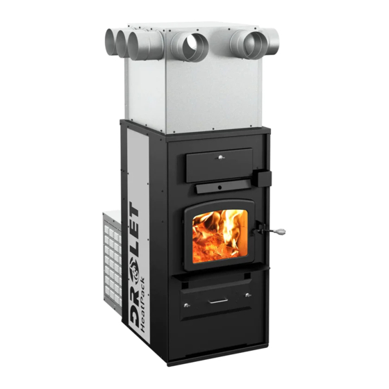
Installation and operating instructions for the
HEATPACK WOOD FURNACE
(
model)
DF00500
Verified and tested for Canada
and the United States
by an accredited laboratory
Stove Builder International Inc.
250, rue de Copenhague,
St-Augustin-de-Desmaures (Quebec)
Canada G3A 2H3
After-sale service: 418-908-8002
E-mail: tech@sbi-international.com
This manual is available for free download on the manufacturer's web site. It is a
copyrighted document. Re-sale is strictly prohibited. The manufacturer may update this
manual from time to time and cannot be responsible for problems, injuries, or damages
arising out of the use of information contained in any manual obtained from unauthorized
sources.
Please keep this document!
READ THESE INSTRUCTIONS CAREFULLY BEFORE INSTALLING AND
OPERATING YOUR FURNACE.
PLEASE KEEP THIS MANUAL FOR REFERENCE
45867A
Printed in Canada
19-03-2019
Advertisement
Table of Contents
Troubleshooting

Related Manuals for Drolet HeatPack DF00500


Summary of Contents for Drolet HeatPack DF00500
- Page 1 Installation and operating instructions for the HEATPACK WOOD FURNACE model) DF00500 Verified and tested for Canada and the United States by an accredited laboratory Stove Builder International Inc. 250, rue de Copenhague, St-Augustin-de-Desmaures (Quebec) Canada G3A 2H3 After-sale service: 418-908-8002 E-mail: tech@sbi-international.com This manual is available for free download on the manufacturer’s web site.
- Page 2 HeatPack Furnace Installation and Operation Manual THANK YOU FOR CHOOSING THIS DROLET WOOD FURNACE As one of North America’s largest and most respected wood stove, furnace and fireplace manufacturers, Stove Builder International takes pride in the quality and performance of all its products.
-
Page 3: Table Of Contents
HeatPack Furnace Installation and Operation Manual Table of contents PART 1 – INSTALLATION ................6 1 Introduction ..................... 6 2 Regulations and safety warnings covering installation ....... 7 2.1 Regulations covering furnace installation ..............7 2.1.1 Cautions and warnings covering installation ..............7 3 Furnace contents .................. - Page 4 HeatPack Furnace Installation and Operation Manual 7.2.1 Assembling the plenum extension (A) ................20 7.2.2 Assembling the hot air distribution plenum (B) ..............21 7.2.3 Assembling the plenum extension (A) with the plenum (B) ..........22 7.2.4 Installing the start-off adapters ..................23 7.3 Installation of the assembled plenum on the furnace ..........
- Page 5 14.4 The SBI commitment to you and the environment ............ 77 14.4.1 What is your new furnace made of? ................. 77 15 Safety information ................. 78 15.1 Cautions and warnings ..................... 78 15.2 Smoke detector ......................80 15.3 Chimney fire ......................80 DROLET LIMITED LIFETIME WARRANTY ..........81...
-
Page 6: Part 1 - Installation
HeatPack Furnace Installation and Operation Manual PART 1 – INSTALLATION Refer to Part 2 of this manual for operation, maintenance and troubleshooting instructions. Refer to Part 3 of this manual for the furnace features and safety instructions. 1 Introduction This furnace uses the same wood burning technology as a high efficiency certified CSA B415.1-10. -
Page 7: Regulations And Safety Warnings Covering Installation
HeatPack Furnace Installation and Operation Manual 2 Regulations and safety warnings covering installation 2.1 Regulations covering furnace installation WARNING FOLLOW LOCAL CODES IF IN DOUBT, CONTACT YOUR LOCAL HEATING APPLIANCE RETAILER, YOUR MUNICIPALITY OR YOUR FIRE DEPARTMENT. Installation must be made in accordance with the following standards : −... -
Page 8: Furnace Contents
HeatPack Furnace Installation and Operation Manual • DO NOT STORE NEAR WOOD FURNACE. RESPECT THE PRESCRIBED CLEARANCE BETWEEN COMBUSTIBLES AND HEAT. • DO NOT CONNECT THIS UNIT TO A CHIMNEY FLUE SERVING ANOTHER APPLIANCE. • DO NOT INSTALL IN A MOBILE HOME. •... -
Page 9: Authorized And Non-Authorized Installation Configuration
HeatPack Furnace Installation and Operation Manual 4 Authorized and non-authorized installation configuration 4.1 Authorized installation configuration in Canada and United States The wood furnace is the only appliance connected to the hot air distribution duct system and air return duct system. 4.2 Authorized installation configuration in United States only 4.2.1 Parallel installation (A) represents the wood furnace. -
Page 10: Non-Authorized Installation Configuration
HeatPack Furnace Installation and Operation Manual 4.3 Non-authorized installation configuration 4.3.1 Non-authorized installation configuration in Canada and United States • The hot air distribution duct of the furnace (A) must not be installed in the air return duct of the furnace (B). •... -
Page 11: Clearances To Combustible Material
HeatPack Furnace Installation and Operation Manual Location: You will find the certification label on the back of the appliance. Information found on the certification label always overrides the information published in any other publication. Content of certification label: Model number, serial number, certification agency, standards, clearances to combustible material, as well as the main safety cautions. -
Page 12: Cold Air Return Ductwork Clearances
HeatPack Furnace Installation and Operation Manual MINIMUM CLEARANCES 14" (356mm) 18" (457mm) 5" (127mm) 1" (25mm) 72" (1828 mm) 11" (279 mm) 24" (610 mm) REQUIRED MEASURMENTS 24" (610mm) 5.3.2 Cold air return ductwork Clearances The air return duct can be connected to a new or to an existing air return ductwork. -
Page 13: Clearances To Combustibles Materials For Hot Air Distribution Duct
HeatPack Furnace Installation and Operation Manual 5.3.3 Clearances to combustibles materials for hot air distribution duct The hot air distribution duct can be passed through a wall with a clearance of 1" (25mm) around it. The clearance of the hot air distribution duct with combustibles material is 1" (25mm). 5.4 Floor protection If the floor is made of non combustible material, no floor protector is required. -
Page 14: The Exhaust System
HeatPack Furnace Installation and Operation Manual 6 The exhaust system WARNING DO NOT INSTALL A MANUAL DAMPER IN THE EXHAUST PIPE ON THIS FURNACE. CAUTION BEFORE CONNECTING THE FURNACE TO THE EXHAUST SYSTEM, SURE THAT THE EXHAUST PIPE AND/OR THE EXCHANGERS OF THE FURNACE ARE FREE OF ALL ITEMS. -
Page 15: Masonry Chimneys
HeatPack Furnace Installation and Operation Manual Recommended installation Not recommended installation Inside chimneys recommended An outside chimney will create problems because even when no fire is burning, there because it creates a cold backdraft, if the is normally an upward flow in the system. furnace is installed in the lower part of the house. -
Page 16: The Exhaust Pipe / Flue Collar
HeatPack Furnace Installation and Operation Manual 6.2 The exhaust pipe / Flue collar The recommended exhaust pipe inner diameter is 6" (152 mm). If an increaser / reducer must be used (max 6" (152 mm) to 7" (178 mm)), it must be installed as close as possible to the chimney. - Page 17 HeatPack Furnace Installation and Operation Manual • Maximum unsupported horizontal length: 3 feet (1 m); • Galvanized flue pipes must not be used because the coating vaporize at high temperatures and release dangerous gases; • Flue pipes must be at least 24 gauge in thickness; •...
-
Page 18: Hot Air Distribution And Air Return System
HeatPack Furnace Installation and Operation Manual 7 Hot air distribution and air return system The Drolet furnace is designed and equipped with a hot air distribution plenum who can receive 6 to 10, 6" (152 mm) diameter round ducts. WARNING THE INSTALLER IS RESPONSIBLE OF THE PERFORMANCE OF THE HOT AIR DISTRIBUTION DUCTS AND THE AIR RETURN SYSTEM. -
Page 19: Adjustable Height Of The Plenum; (With The Plenum Extension Cut Off A)
HeatPack Furnace Installation and Operation Manual 7.1.2 Adjustable height of the plenum; (with the plenum extension cut off A). When the ceiling height, measured from the floor is greater than 72" (183 cm), but less than 84" (213 cm), it will be possible to cut the plenum extension (A) of at most 10"... -
Page 20: Assembling The Plenum Extension (A) And The Hot Air Distribution Plenum (B)
HeatPack Furnace Installation and Operation Manual 7.2 Assembling the plenum extension (A) and the hot air distribution plenum (B). 7.2.1 Assembling the plenum extension (A) Step 1 : Assemble the plenum extension panels (A) with 12 black screws (C) #10 x 5/8" robertson type A provided in the user manual. -
Page 21: Assembling The Hot Air Distribution Plenum (B)
HeatPack Furnace Installation and Operation Manual 7.2.2 Assembling the hot air distribution plenum (B) Step 1: Insert the male end of each Step 2 : Secure the assembly by bending the panel (B) in the female part of the two metal tabs in the center of each corner. adjacent panel. -
Page 22: Assembling The Plenum Extension (A) With The Plenum (B)
HeatPack Furnace Installation and Operation Manual 7.2.3 Assembling the plenum extension (A) with the plenum (B) Slide plenum (B) over the plenum extension (A) to the extent determined in section 7 - Hot air distribution and air return system Using 13 self-drilling screws, secure plenum plenum extension (A). -
Page 23: Installing The Start-Off Adapters
HeatPack Furnace Installation and Operation Manual 7.2.4 Installing the start-off adapters After choosing your output configuration, you can now install the start-off adapters. They can be found in the boxes 1 & 2 of the furnace. Each box contains 5 adapters. Do the following to install the start-off adapters. -
Page 24: Installation Of The Assembled Plenum On The Furnace
HeatPack Furnace Installation and Operation Manual 7.3 Installation of the assembled plenum on the furnace Step 1 : Identify the right side of the plenum, it Step 2 : Install the assembly on the is provided with holes for the installation of the furnace, taking care to insert the 4 fold “RTD”... -
Page 25: Minimum Amount Of Outlets And Maximum Lengths Of Ducts
HeatPack Furnace Installation and Operation Manual 7.3.1 Minimum amount of outlets and maximum lengths of ducts • A minimum of 6 start-off adapters must be installed on the start-off plenum. The location of the adapters has no impact on the distribution of air. •... - Page 26 HeatPack Furnace Installation and Operation Manual The total area of secondary duct outlets must be equal or slightly less than the total area of the outlets used on the hot air distribution plenum (B). Example of surface calculation according to the number of outlets used in the plenum: Total surface of Diameter of plenum...
-
Page 27: Static Pressure Calibration
HeatPack Furnace Installation and Operation Manual WARNING ACORDING TO THE NATIONAL BUILDING CODE, THE BTU/H PROVIDED BY AN OUTLET ON THE PLENUM MUST NOT EXCEED 10,250 BTU/H (3KW) AND THE HOT AIR TEMPERATURE AT THE OUTLET OF A SECONDARY DUCT SHOULD NOT EXCEED 158 °F (70 °C). -
Page 28: Electrical Connection, Adjustment Of Components And Calibration Of The Draw
HeatPack Furnace Installation and Operation Manual o Mechanical ventilation system: if the house is equipped with a ventilation system (air exchanger or heat recovery), the ventilation system may provide sufficient auxiliary air to the solid fuel unit. Otherwise, the owner should be informed that the ventilation system may have to be rebalanced by a ventilation technician after the installation of the solid fuel unit. - Page 29 HeatPack Furnace Installation and Operation Manual...
-
Page 30: Installation And Connection Of The "Rtd" Thermal Probe
HeatPack Furnace Installation and Operation Manual 9.2 Installation and connection of the “RTD” thermal probe IMPORTANT THE PROPER POSITIONING OF THE “RTD” THERMAL PROBE IS ESSENTIAL TO THE PROPER FUNCTIONING OF THE FURNACE. INSTALL IT IN THE OPENING PROVIDED FOR THIS PURPOSE ON THE START-OFF PLENUM. 9.2.1 With plenum (B) only Step 1. - Page 31 HeatPack Furnace Installation and Operation Manual Step 3. Pre drill the two top RTD probe support holes with a 1/8" drill bit in the furnace plenum. Secure it in place with two screws (C). Step 4. Install the RTD probe (N) in its support and secure it in place with 2 screws (C). Plug the RTD probe in the connector located at the back of the furnace.
-
Page 32: With The Plenum Extension (A) And The Plenum (B)
HeatPack Furnace Installation and Operation Manual 9.2.2 With the plenum extension (A) and the plenum (B) Step 1. Pre drill the four plate holes (L) on the plenum with a 1/8" drill bit. Using 4 self- drilling screws (D), install the plate (L) supplied with the furnace on the plenum (B). Make sure to have the notch on the plate up. - Page 33 HeatPack Furnace Installation and Operation Manual Step 3. Install the RTD probe (L) in its support and secure it in place with 2 screws (C). Plug the RTD probe in the connector located at the back of the furnace. NOTE IT IS POSSIBLE TO SEE THE TEMPERATURE READ BY THE RTD BY PRESSING THE LEFT BUTTON ON THE DIGITAL DISPLAY AT THE BACK OF THE FURNACE.
-
Page 34: Blower Technical Data
HeatPack Furnace Installation and Operation Manual 9.3 Blower technical Data The blower speed must conform to the recommendations of the Warm Air Heating and Air Conditioning National Association and should respect the static pressure ranges in the warm air plenum of the furnace. TEMP STATIC OPTIONAL... -
Page 35: The Use Of A Thermometer
HeatPack Furnace Installation and Operation Manual 9.4.1 The use of a thermometer The first use of a thermometer is to inform the user about the discharge temperature of flue gases. Without accurate measurement of the draft using a pressure gauge (manometer), the thermometer will indicate if the temperature is ideal, too low or too high. -
Page 36: Appendix 1: Optional Thermostat Installation
HeatPack Furnace Installation and Operation Manual Appendix 1: Optional thermostat installation Using a thermostat will help you maintain a constant temperature throughout the house. A fixed wall mounted 24v thermostat is required. NOTE THERMOSTAT MANUFACTURER’S INSTRUCTION ALWAYS OVERRIDES THE INFORMATION PUBLISHED IN THE FOLLOWING SECTION. Thermostat location Must be installed on an inside wall of the house;... - Page 37 HeatPack Furnace Installation and Operation Manual Example of thermostat wiring: Connect one wire to "RH" and the other wire to "W". The red jumper can be left in place. For more information, refer to the manufacturer's instructions. Thermostat wiring – Parallel Installation This furnace may be installed in parallel as an add-on to an existing furnace in the USA only.
- Page 38 HeatPack Furnace Installation and Operation Manual Step 2. From the thermostat connected to the existing furnace, connect 2 new wire (H) on the Rh and W terminals of your thermostat and fix them to the terminal on the circuit board labeled "I" (interlock) of the Add-On furnace. When the wood furnace receives the signal from the existing furnace’s thermostat calling for heat, it will disconnect the existing furnace damper motor, sending the wood furnace in low burn until the call for heat from that thermostat is satisfied.
-
Page 39: Appendix 2: Optional Air Filters (Ac01390, Ac01391)
HeatPack Furnace Installation and Operation Manual Appendix 2: Optional air filters (AC01390, AC01391) The filter option (AC01390 – cardboard frame or AC01391 – washable aluminum) allows filtrating dust and other particles before distributing warm air in your installation in addition of protecting your blower. -
Page 40: Appendix 3: Optional Air Return Adapter (Ac01392)
HeatPack Furnace Installation and Operation Manual Appendix 3: Optional Air return adapter (AC01392) The optional air return adapter (AC01392) can be added to the furnace to increase the efficiency of your system. This option allows you to take in the fresh air from the rooms connected to the return system and bring it back towards the furnace to be heated. -
Page 41: Part 2 - Oeration, Maintenance And Troubleshooting
HeatPack Furnace Installation and Operation Manual PART 2 – OERATION, MAINTENANCE AND TROUBLESHOOTING Please see Part 1 for installation instructions. Please see Part 3 for features and safety instructions. 9.5 How to prepare or buy good firewood 9.5.1 What is good firewood? Good firewood has been cut to the correct length for the furnace, split to a range of sizes and stacked in the open until its moisture content is reduced to 15% to 20%. -
Page 42: Piece Size
HeatPack Furnace Installation and Operation Manual 9.5.4 Piece size Firewood dries more quickly when it is split. Large unsplit rounds can take years to dry enough to burn. Even when dried, unsplit logs are difficult to ignite because they don’t have the sharp edges where the flames first catch. -
Page 43: Judging Firewood Moisture Content
HeatPack Furnace Installation and Operation Manual Here are some things to consider in estimating drying time: • Firewood takes a long time to dry • Firewood bought from a dealer is rarely dry enough to burn, so it is advisable to buy the wood in spring and dry it yourself •... -
Page 44: Operating Your Furnace
HeatPack Furnace Installation and Operation Manual 10 Operating your furnace 10.1 Your first fires Two things will happen as you burn your first few fires; the paint cures and the internal components of the furnace are conditioned. As the paint cures, some of the chemicals vaporize. The vapours are not poisonous, but they do smell bad. -
Page 45: The Top Down Fire
HeatPack Furnace Installation and Operation Manual 10.2.2 The top down fire The top down fire starting method solves two problems with the conventional method: first, it does not collapse and smother itself as it burns; and second, it is not necessary to build up the fire gradually because the firebox is loaded before the fire is lit. -
Page 46: Raking Charcoal
HeatPack Furnace Installation and Operation Manual When you burn in cycles, you rarely need to open the furnace’s loading door while the wood is burning. This is an advantage because smoke could escape from the furnace when the door is opened as a full fire is burning. This is especially true if the chimney connector has 90 degree elbows and if the chimney runs up the outside wall of the house. -
Page 47: Firing Each New Hot Load
HeatPack Furnace Installation and Operation Manual 10.3.3 Firing each new hot load Place the new load of wood on and behind the charcoal, and not too close to the glass. Close the door and open the air control damper. Leave the air control damper open until the firebox is full of flames, the wood has charred to black and its edges are glowing red. -
Page 48: Building Different Fires For Different Needs
HeatPack Furnace Installation and Operation Manual The following figure shows the position of the air control damper (A) according to the position of the air control damper switch (B). 10.3.5 Building different fires for different needs Using the air control is not the only way to match the furnace’s heat output to the heat demand. -
Page 49: Control Of The Air Inlet Damper
HeatPack Furnace Installation and Operation Manual 10.3.5.3 High output fires for cold weather When the heat demand is high during cold weather, you’ll need a fire that burns steadily and brightly. This is the time to use your biggest pieces of hardwood fuel if you have it. Put the biggest pieces at the back of the firebox and place the rest of the pieces compactly. -
Page 50: Additional Fresh Air Supply
HeatPack Furnace Installation and Operation Manual Reducing the combustion air will do two things. First, the combustion rate will decrease, which will spread the thermal energy of the fuel over a longer period of time. In addition, the velocity of the exhaust gas decreases, which allows better heat transfer in the heat exchanger and chimney. -
Page 51: Manual Or Thermostat Control
HeatPack Furnace Installation and Operation Manual 10.5 Manual or thermostat control From factory, the opening and closing of the air inlet damper is manually activated by the means of a switch located at the rear of the furnace. The switch has two positions; opened and closed. -
Page 52: Prolonged Power Outage
HeatPack Furnace Installation and Operation Manual 10.7 Prolonged power outage To reduce the risk of overheating during a prolonged power outage (more than 10 minutes), it is recommended damper is closed. If your furnace is equipped with the optional filter, remove the air filter to improve the circulation of air around the combustion chamber of the furnace. -
Page 53: Door Adjustment
HeatPack Furnace Installation and Operation Manual When the weather is mild, you may find that letting the fire go out is better than trying to maintain a continuous fire. Use the technique described above for building a fire to take the chill off the house. -
Page 54: Replacement Of The Glass And Gaskets
HeatPack Furnace Installation and Operation Manual 11.1.4 Replacement of the glass and gaskets After a year or more of use, the gasket of the door will compress and become hard which can allow air to pass. You can check the air tightness of your door gasket by closing and locking the door on a piece of paper. -
Page 55: Cleaning And Painting The Furnace
HeatPack Furnace Installation and Operation Manual 8. Install the new gasket on the glass. Remove a part of the paper covering the gasket adhesive. Center the gasket on the edge of the glass so that when folded and glued, the gasket is equal on both sides. -
Page 56: Heat Exchangers Care
HeatPack Furnace Installation and Operation Manual For best results, use the same paint that was originally used on the furnace, which is available in spray cans. See your dealer for details. 11.1.6 Heat exchangers care Heat exchangers must be cleaned thoroughly at the end of every heating season. During summer, the air in basements is damper and with minimal air circulation within the furnace, it can mix with creosote and/or sooth deposits in the exchangers to form an acid that could accelerate the corrosion process and induce premature decay of the steel. - Page 57 HeatPack Furnace Installation and Operation Manual 3. Use the tool provided, clean the three exchanger pipes. 4. Dirt in the exchangers 1 and 3 fall into the combustion chamber, at the rear.
- Page 58 HeatPack Furnace Installation and Operation Manual 5. Dirt in the central exchanger (2) will be removed from the front or the rear of the furnace. If you remove dirt from the central exchange to the back of the furnace, remove the black pipe connector in order to dispose of the dirt. 6.
-
Page 59: Chimney And Chimney Connector Maintenance
HeatPack Furnace Installation and Operation Manual 11.2 Chimney and chimney connector maintenance 11.2.1 Why chimney cleaning is necessary Wood smoke can condense inside the chimney connector and chimney, forming a combustible deposit called creosote. If creosote is allowed to build up in the venting system it can ignite when a hot fire is burned in the furnace and a very hot fire can progress to the top of the chimney. -
Page 60: Smoke Pipe Inspection
HeatPack Furnace Installation and Operation Manual CAUTION BEFORE INSTALLING THE FIREBRICK, CHECK TO ENSURE THAT NONE ARE BROKEN OR DAMAGED IN ANY WAY. IF SO, HAVE THE DAMAGED ONES REPLACED. CHECK THE FIREBRICK FOR DAMAGE AT LEAST ANNUALLY AND REPLACE ANY BROKEN OR DAMAGED ONES WITH NEW ONES. INSPECTION AND CLEANING OF THE CHIMNEY IS FACILITATED BY THE REMOVABLE BAFFLE. -
Page 61: Troubleshooting
HeatPack Furnace Installation and Operation Manual 12 Troubleshooting PROBLEMS CAUSES SOLUTIONS Heating inefficient during the Improper adjustment of the Adjust the damper, minimize first combustions. Lack of barometric damper (opened the smoke pipe length and use draft. too wide). Chimney flue elbows. -
Page 62: Installation Of Secondary Air Tubes
HeatPack Furnace Installation and Operation Manual 12.1 Installation of secondary air tubes IMPORTANT OPERATION OF YOUR FURNACE WITHOUT THE BAFFLE MAY CAUSE UNSAFE HAZARDOUS TEMPERATURE CONDITIONS WILL VOID WARRANTY. 1- Starting with the rear tube, lean and insert the right end of the secondary air tube into the rear right channel hole. -
Page 63: Baffle Removal Or Replacement
HeatPack Furnace Installation and Operation Manual Important Notes: The air tubes are identified for placement as follows: Model Type of tube Front (1) ► 66 holes of 0.109" HEATPACK Middle front (2) ► 33 holes of 0.109" Middle rear (3) ► 33 holes of 0.109" Rear (4) ►... -
Page 64: Exploded Diagram And Parts List
HeatPack Furnace Installation and Operation Manual 13 Exploded diagram and parts list... - Page 65 HeatPack Furnace Installation and Operation Manual...
- Page 66 HeatPack Furnace Installation and Operation Manual...
- Page 67 HeatPack Furnace Installation and Operation Manual...
- Page 68 HeatPack Furnace Installation and Operation Manual...
- Page 69 HeatPack Furnace Installation and Operation Manual...
- Page 70 HeatPack Furnace Installation and Operation Manual IMPORTANT: THIS IS DATED INFORMATION. When requesting service or replacement parts for your furnace, please provide the model and the serial number. We reserve the right to change parts due to technology upgrade or availability. Contact an authorized dealer to obtain any of these parts.
- Page 71 HeatPack Furnace Installation and Operation Manual Item Description 28061 CHROME ASH DRAWER HANDLE SE51783 ASH DRAWER 24096 ROUND CAST IRON ASH PLUG 21441 SIDE PANEL INSULATION PL36114 4" X 7 3/4'' X 1 1/4'' REFRACTORY BRICK 29000 4'' X 8'' X 1 1/4'' REFRACTORY BRICK 29015 4'' X 9'' X 1 1/4'' REFRACTORY BRICK PL36060...
- Page 72 HeatPack Furnace Installation and Operation Manual Item Description PL48170 HEAT EXCHANGER SCRAPER PL48173 POKER 44171 MOISTURE READER...
-
Page 73: Part 3 - Features And Safety
HeatPack Furnace Installation and Operation Manual PART 3 – FEATURES AND SAFETY Please see Part 1 for installation instructions. Please see Part 2 for operation, maintenance and troubleshooting instructions. 14 General information on HeatPack (DF00500) 14.1 Appliance performance Fuel type Dry cordwood Recommended heating area 500 to 1,500 ft²... -
Page 74: General Features
HeatPack Furnace Installation and Operation Manual 14.2 General Features Maximum log length 20" (533 mm) north-south** Diameter of the flue collar 6 in. (152 mm) Recommended connector pipe diameter 6 in. (152 mm) Recommended chimney diameter 6 in. (152 mm) Required type of chimney CAN/ULC S629, UL 103 HT (2100 °F) Baffle material... -
Page 75: Technical Data Heatpack
HeatPack Furnace Installation and Operation Manual 14.2.1 Technical data HeatPack... - Page 76 HeatPack Furnace Installation and Operation Manual...
-
Page 77: The Benefits Of Low Emissions And High Efficiency
HeatPack Furnace Installation and Operation Manual 14.3 The benefits of low emissions and high efficiency The low smoke emissions produced by the special features inside the Brand Model firebox mean that your household will release up to 90 percent less smoke into the outside environment than if you used an older conventional wood furnace. -
Page 78: Safety Information
HeatPack Furnace Installation and Operation Manual Safety information 15.1 Cautions and warnings • A CARBON MONOXIDE (CO) DETECTOR/ALARM IS REQUIRED IN THE ROOM IN WHICH THE FURNACE IS INSTALLED. • HOT WHILE IN OPERATION, KEEP CHILDREN, CLOTHING AND FURNITURE AWAY. CONTACT MAY CAUSE SKIN BURNS. GLOVES MAY BE NEEDED FOR FURNACE OPERATION. - Page 79 HeatPack Furnace Installation and Operation Manual • DO NOT USE LIQUIDS SUCH AS KEROSCENE OR DIESEL FUEL TO START A FIRE. • DO NOT ELEVATE THE FIRE BY USING A GRATE IN THIS FURNACE. • DO NOT INSTALL AN AUTOMATIC FEEDER ON THIS FURNACE. •...
-
Page 80: Smoke Detector
HeatPack Furnace Installation and Operation Manual WARNING: This product can expose you to chemicals including carbon monoxide, which is known to the State of California to cause cancer, birth defects or other reproductive harm. For more information go to www.P65warnings.ca.gov/ 15.2 Smoke detector We highly recommend the use of a smoke detector. -
Page 81: Drolet Limited Lifetime Warranty
Labour cost and repair work to the account of the manufacturer are based on a predetermined rate schedule and must not exceed the wholesale price of the replacement part. Shall your unit or a components be defective, contact immediately your DROLET dealer. To accelerate processing of your warranty claim, make sure to have on hand the following information when calling: •...
Need help?
Do you have a question about the HeatPack DF00500 and is the answer not in the manual?
Questions and answers