Table of Contents

Summary of Contents for Williams Sound SoundPlus WIR TX300
- Page 1 Installation Guide & User Manual ® SoundPlus WIR TX300 Infrared System Large Area Infrared Listening System Modulator Model WIR MOD 1 Transmitter Model WIR TX3 ® Williams Sound Receiver Models WIR RX1, RX3, RX4 Helping People Hear MAN 046C...
-
Page 2: Table Of Contents
Hi-Pass Filter Setting Testing the System Receiver Instructions Battery Information Suggestions For Receiver Management Troubleshooting Warranty Specifications Note: Taking a few minutes now to read these instructions will save time and ensure proper system operation. ® Williams Sound Helping People Hear... -
Page 3: Introduction
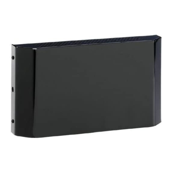
A single TX3 infrared transmitter will cover approximately 10,000 square feet of listening area. Larger areas can be covered with additional The Williams Sound WIR TX300 Infrared System transmitters. The transmission is confined within consists of a MOD 1 Modulator and one or more... -
Page 4: Controls And Features
Audio Inputs 50-60 Hz, 10VA Input Level Unbalanced Line 175 Hz Plug 20 Hz 725 Hz 6dB/octave Left Right 75 Ohm 75 Ohm Power: 24 VAC, 60 Hz, 50VA Made in USA Williams Sound Corp. ® Williams Sound Helping People Hear... -
Page 5: Tx3 Transmitter
EQUIPMENT TO RAIN OR MOISTURE. Modulation Out Modulation In 24 VAC Power In, (75 Ohm) (75 Ohm) 50-60 Hz, 35W Williams Sound Corp., Minneapolis, Minnesota, USA Made in U.S.A. Williams Sound ® Helping People Hear TX3 Front TX3 Rear Step 1: Infrared Transmitter... - Page 6 It’s O.K. (and desirable) for the illumination patterns to overlap when Fig. 6: Side Perspective 120' SCREEN STAGE ® Williams Sound Helping People Hear...
-
Page 7: Mounting Tx3 Transmitter To Wall Or Ceiling
DO NOT over- tighten. Jam Nut If rotational adjustment is required, use a 7/16" open-end wrench to loosen the jam Front of TX3 nut on the ballshaft. Rotate the transmitter and re-tighten the jam nut. ® Williams Sound Helping People Hear... -
Page 8: Transmitter Power Wiring
Modulation Out Modulation In 24 VAC Power In, (75 Ohm) (75 Ohm) 50-60 Hz, 35W Williams Sound Corp., Minneapolis, Minnesota, USA Made in U.S.A. Baseband Output Connection Power Connection Connect to MOD 1 here Plug in Power Supply using RG-59 cable. -
Page 9: 95 Khz Carrier Cable Connection
6dB/octave Left Right 75 Ohm 75 Ohm Power: 24 VAC, 60 Hz, 50VA Made in USA Williams Sound Corp. Baseband Output Connection Power Connection Connect to TX3 here using RG-59 cable. Plug in Power Supply ® Williams Sound Helping People Hear... -
Page 10: 95 Khz Carrier Cable Connection
20Hz setting can be used. For hearing assistance, the Williams Sound Authorized Dealer or a local radio 725Hz setting can be used to compensate for typical parts store. If the TAPE OUT jack is already in use, high-frequency hearing loss. -
Page 11: Testing The System
To avoid transmitter(s) to obtain the best coverage. draining the battery, make sure the receiver If coverage is not adequate, additional is turned off when not in use. transmitter panels must be used. ® Williams Sound Helping People Hear... -
Page 12: Battery Information
The receiver should always be turned OFF while charging. It takes about 14 hours to fully charge the battery. If the battery is providing very short service life (under 1 hour of use) let it drain completely by ® Williams Sound Helping People Hear... -
Page 13: Suggestions For Receiver Management
Make sure the 24VAC power supplies are physical damage. This warranty applies only to working. products returned to Williams Sound for service. To return a product for service, call Williams Sound No sound through receivers. Corp. at 1-800-843-3544 and request a Return If some of the receivers work but others don’t,... -
Page 14: Specifications
10K½ nominal load 2-conductor, screw-terminals Power Connections: impedance Transmitter Type: For use with Williams Sound WIR TX1, WIR Infrared Test LED: IR LED for receiver testing, monitoring, TX2, WIR TX3 Transmitter/Emitter panels. and audio signal testing Each MOD 1 Modulator can drive two Transmitter panels directly. - Page 15 Williams Sound Corp. 10321 West 70th St., Eden Prairie, MN 55344-3446 U.S.A. 800-843-3544 / 952-943-2252 / FAX: 952-943-2174 © 1996, Williams Sound Corp. MAN 046C...


Need help?
Do you have a question about the SoundPlus WIR TX300 and is the answer not in the manual?
Questions and answers