
Related Manuals for Jorjin MM5D91E0B


Summary of Contents for Jorjin MM5D91E0B
- Page 1 MM5D91E0B MM5D91-0B Entrance Counter Evaluation Kit User Guide Draft 0.1 Copyright © JORJIN TECHNOLOGIES INC. 2020 http://www.jorjin.com.tw CONFIDENTIAL...
-
Page 2: Table Of Contents
Doc No: MM5D91E0B-UG-D01 Index 1. INTRODUCTION ........................2 2. HARDWARE DESCRIPTION ....................3 2.1. H ....................3 ARDWARE VERVIEW 2.2. S ....................4 CHEMATIC IAGRAMS 2.3. D ......................... 6 IMENSIONS 3. SOFTWARE DESCRIPTION ....................7 3.1. M .................... 7 ODULE... -
Page 3: Introduction
61.0 to 61.5GHz, and it includes the ARM Cortex-M4F based processor system, 1Tx 3Rx antenna and onboard regulator. The Jorjin mmWave Radar sensor evaluation kit MM5D91E0B shows as below. Based on the MM5D91-0B Radar sensor module, evaluation board is built to demonstrate the function of entrance counter of the 60 GHz radar sensor with its sophisticated radar presence detection algorithms. -
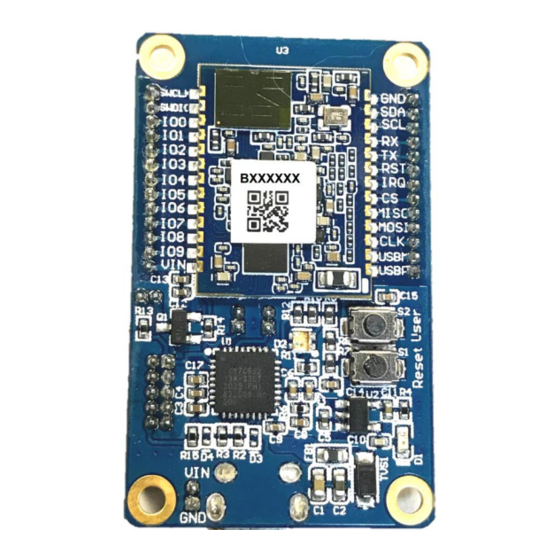
Page 4: Hardware Description
Table 2-1. Evaluation Kit component descriptions list Region Description Jorjin mmWave Radar sensor module. User - Press the button and power up or reset to enter bootloader mode. Reset - Radar sensor module reset switch. LED of radar detect status: Green color: No people detected. -
Page 5: Schematic Diagrams
Doc No: MM5D91E0B-UG-D01 2.2. Schematic Diagrams Pin assignment of P1 and P2: LED indication for presence detection: © Copyright JORJIN TECHNOLOGIES INC. 2020 Page 4 http://www.jorjin.com.tw CONFIDENTIAL... - Page 6 Doc No: MM5D91E0B-UG-D01 UART to USB Conversion: USB circuit: © Copyright JORJIN TECHNOLOGIES INC. 2020 Page 5 http://www.jorjin.com.tw CONFIDENTIAL...
-
Page 7: Dimensions
Doc No: MM5D91E0B-UG-D01 2.3. Dimensions MM5D91E0B Board Dimensions. 26 mm © Copyright JORJIN TECHNOLOGIES INC. 2020 Page 6 http://www.jorjin.com.tw CONFIDENTIAL... -
Page 8: Software Description
Doc No: MM5D91E0B-UG-D01 3. SOFTWARE DESCRIPTION 3.1. Module Config Software The Entrance Counter Config tool in the link: TBD Connect the radar board to PC through USB, open the config tool. If the OS is Windows 7 or lower, please find the USB driver in the link. - Page 9 Doc No: MM5D91E0B-UG-D01 Select the correct COM port number (e.g. COM6) and press Connect button. If the board is successfully connected, a firmware version would be shown in the box. Otherwise, a fail message would be shown at bottom. ©...
-
Page 10: Set And Get Configuration
Doc No: MM5D91E0B-UG-D01 3.2. Set and Get Configuration User can set or get the configuration of the radar at the Config tab page. Currently following items are available: Item Description Version Get the firmware version in MCU. Counter detect on/off Set entrance counter detect on or off. - Page 11 Doc No: MM5D91E0B-UG-D01 © Copyright JORJIN TECHNOLOGIES INC. 2020 Page 10 http://www.jorjin.com.tw CONFIDENTIAL...
-
Page 12: Getting Start With Smart Entrance Counter Solution
Doc No: MM5D91E0B-UG-D01 3.3. Getting Start with Smart Entrance Counter Solution User can set or get the configuration of the radar at the Counter event tab page. Currently setting items are available: ⚫ Sensor Position : Depending on the location of installation, select either ceiling or side. -
Page 13: Firmware Update
Doc No: MM5D91E0B-UG-D01 3.4. Firmware update Firmware update can be done in the Firmware update tab page. Select the target .bin file by pressing Select button. Bootloader mode would be entered automatically during the update process. In case a non-working firmware is loaded, user can manually force the module to enter bootloader mode by pressing the user button on the mother board after power up or reset. -
Page 14: Smart Entrance Counter Setup
Doc No: MM5D91E0B-UG-D01 4. SMART ENTRANCE COUNTER SETUP The Radar evaluation kit can be mounted in following ways: ⚫ Side mount: Portrait orientation at around 1.1-1.5m on a wall/door/pillar in such a way that radar sensor is facing the entry/exit passage from side for people counting. For side mount, it is recommended to set the maximum range parameter based on the width of the entrance in such a way that it is lesser than the distance of sensor to the wall (if any). - Page 15 Doc No: MM5D91E0B-UG-D01 ⚫ Top/Ceiling mount: Mounted at a height of up to 3 m from ground, sensor board longer edge (FOV Elevation) being perpendicular to the passage. It is recommended to limit the maximum range of solution to the height of sensor board from ground for good performance.
-
Page 16: History Change
Doc No: MM5D91E0B-UG-D01 ⚫ Operating Sequence: 1. Initial: Traffic light is GREEN 2. Person enters RED area: Traffic light switch to RED (STOP) 3. Person stays in whole sensor area: light keeps RED (STOP) 4. Person goes out of sensor area: light switches to GREEN and IN or OUT event is generated respectively 5.
Need help?
Do you have a question about the MM5D91E0B and is the answer not in the manual?
Questions and answers