Dimplex QM050 Installation Instructions Manual
Quantum heater
Hide thumbs
Also See for QM050:
- Operating instructions manual (17 pages) ,
- Installation manual (40 pages)
Advertisement
Quick Links
A world of expertise
Note: These Installation
Instructions are for
Series G heaters only.
Only use the instructions
which accompany the
heater.
11115-10
Rev. 13F/11F
- 1 -
Installation Instructions
IMPORTANT
These instructions should be read carefully and retained for
future use.
Note also the information presented on the appliance.
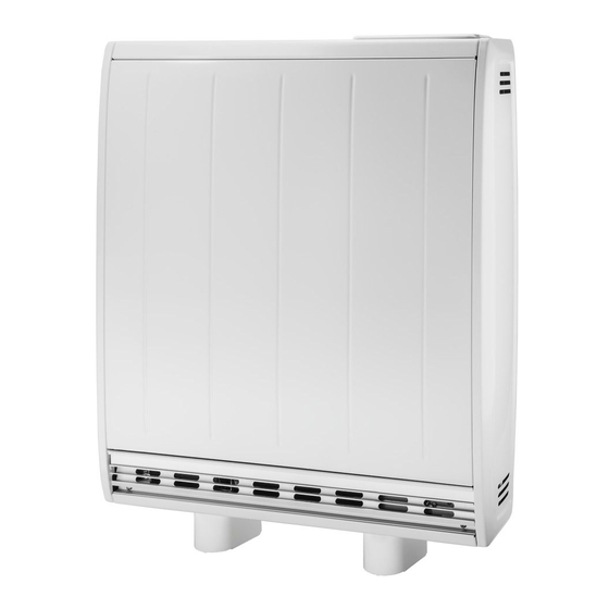
Quantum Heater
Models:
QM050
Boost
Output
230/240V~:
353/385W
Storage
Element
Rating
230/240V~:
936/1020W
Rated
Charge
Period:
7.7 - 7 Hours
Energy
Cells:
12
Installed
Weight:
67kg
kWh:
7.2kWh
QM070
QM100
567/630W
792/880W
1435/1560W
2042/2220W
18
24
91kg
115kg
10.9kWh
15.5kWh
QM125
QM150
1017/1130W
1242/1380W
2540/2760W
3024/3300W
30
36
142kg
165kg
19.3kWh
23.1kWh
Advertisement

Related Manuals for Dimplex QM050


Summary of Contents for Dimplex QM050
- Page 1 Installation Instructions A world of expertise IMPORTANT These instructions should be read carefully and retained for future use. Note also the information presented on the appliance. Quantum Heater Models: QM050 QM070 QM100 QM125 QM150 Boost Output 230/240V~: 353/385W 567/630W 792/880W...
- Page 2 IMPORTANT WARNING - THE SURFACE OF THIS HEATER CAN BE HOT. WARNING - THIS APPLIANCE MUST BE EARTHED. • The installation must be carried out by a suitably qualifi ed individual in accordance with the latest IEE Regulations for IMPORTANT electrical equipment.
- Page 3 fi tted around the heater, as is normal with heating appliances in similar circumstances. A range of guards specially designed for Dimplex heaters is available. If you require further information on these guards, please see contact details on back page of the Operating Instructions.
- Page 4 Fig. 1 2. Secure the feet to the heater. For models QM050, QM070 and QM100 two locations are possible indicated by X and Y markings visible on the base of the heater. Ensure the feet are fi xed at the location holes marked with an ‘...
- Page 5 3. Ensure the heater is stable before removing the screws which hold the grille panel in position. Set the grille to one side. Fig. 3 4. Remove the two screws located towards to bottom of either end of the heater, which retain the heater sides.
-
Page 6: Installing The Heater
Installing the Heater The heater must be securely fi xed to a wall. Screws with suitable wall fi xings for solid walls are provided. If other wall types are encountered it is the installer who must choose the most suitable fi xing. SUGGESTED FIXINGS SOLID BRICK/BLOCK: No. - Page 7 Fig. 6 QM050 7. Six fi xing positions must be selected for each model. Mark the positions for the fi xing holes. QM070 Remove the bracket from the wall, drill the holes Fig.
-
Page 8: Electrical Connections
Warning: Before obtaining access Electrical Connections to terminals, all supply circuits 8. The heater leaves the factory confi gured must be disconnected. to operate with two mains supplies, a 24 hour supply and an off peak switched supply. Two Mains Supplies Storage / Fan circuit Ensure the brown wire is connected to the terminal marked L. - Page 9 9. The mains cable entry bushes and terminal blocks will be visible on the right hand side of the unit. Insert the mains cables through the cable gland at the bottom of the heater in readiness for connection. IMPORTANT - Only heat resistant ordinary polyvinyl chloride sheathed fl...
- Page 10 Building the Heater Core 10. Remove the inner front and insulation to gain access to the core of the heater. Lay the inner front carefully to one side to ensure it is not damaged. Fig. 10 11. Remove the internal packaging. Fig.
- Page 11 Bricks The bricks are supplied separately to the heater in packs of three. The reference number is 047243. 12. The bricks have several grooves on one surface for locating around the elements. The two slots through the centre of the brick create the air passages within the core.
- Page 12 Fig. 14 Fig. 14 14. The third row of brick is positioned in a manner similar to the fi rst row. Again be careful not to damage or dislodge the element. 15. Fit the fourth row of brick above the third row in the upside position.
- Page 13 17. Close the core by refi tting the inner front panel complete with insulation. Ensure the bottom edge is located inside the chassis and that the screws are tightly secured down each edge. Fig. 17 Fig. 17 IMPORTANT Double check all mains connections are secure and excess cable is restrained and not in contact with any of the heater casing.
-
Page 14: Slave Mode
‘Slave Mode’ and press Selector Dial. Select ‘Enable’. Slave Mode Disable Enable Information For cleaning, heater guards or other sales service and Dimplex contact details please refer to the Operating Instructions. - 14 -... - Page 15 - 15 -...
- Page 16 - 16 -...
Need help?
Do you have a question about the QM050 and is the answer not in the manual?
Questions and answers