
Related Manuals for Senlan SB150 Series


Summary of Contents for Senlan SB150 Series
- Page 1 SENLAN INVERTER USER’S MANUAL SB150 Variable Speed Drive Hope Senlan Science & Technology Holding Corp., Ltd.
-
Page 2: Table Of Contents
1. Notes on Safety ......................3 Notes on Safety ..........................3 2 Specifications ....................... 7 2.1 Common specifications for SB150 series ..................7 2.2 Product series ........................... 8 4 Operation and commissioning ................. 20 4.1 Operation and display ........................20 4.3 Quick and optimize commissioning .................... -
Page 3: Preface
Preface Preface Thank you for selecting Senlan SB150frequency inverter series.。SB150 is a compact inverter adopting the optimized high-performance space vector control VVVF arithmetic and featuring elegant appearance, delicate circuit design, ingenious circuit design, simple and practical functions, and reasonable menu arrangements, which supports numerous advanced functions, e.g. - Page 4 Preface SENLAN INVERTER SLANVERT Hope Senlan Science and Technology Holding Co.,ltd Definition of Safety ID Markings Any safety-specific content of this manual may use the following markings for identification. The user is required to follow the instructions of the content identified with safety markings.
-
Page 5: Notes On Safety
1 Notes on Safety 1. Notes on Safety 1.1. Notes on Safety (1) Installation The inverter must not be installed at places with combustibles or in the vicinity of combustibles; otherwise there may cause fire. The inverter must not be installed in an environment exposed to flammable gases; otherwise There may cause explosion. - Page 6 1 Notes on Safety (5)Precautions on transport and package Do not place more inverters than specified in the packaging box. Do not put any heavy object on the inverter. Do not open the cover board during transport. Do not apply any force on the keypad and the cover board while handling the inverter, otherwise there may be a risk of injury to people or damage to equipment.
- Page 7 1 Notes on Safety When the motor is used for the first time or reused after it has not been used for a long period, the motor insulation must be inspected to prevent the damage to the inverter cause by the failed insulation of the motor windings.
- Page 8 1 Notes on Safety If the altitude is above 1000 meters, the inverter should be derated by 1% for every 100m rise .If the carrier frequency is greater than the factory setting, the inverter should be derated by 5% for every 1 kHz increase.
-
Page 9: Specifications
2 Specifications 2 Specifications 2.1 Common specifications for SB150 series Item Description Rated voltage and 3-phase: 220v/380V,50/60Hz frequency Input Voltage: 320~420V; voltage imbalance<3%; frequency:47~63 Hz Allowable range 3-phase, 0V~input voltage, with the error less than 5%. Output voltage output V/F control: 0.00~650.00Hz... -
Page 10: Product Series
2 Specifications Item Description disconnection, stall prevention, etc. Braking resistor、 input/output reactor、 EMI filter、 Profibus-DP module、 remote Options control box、LCD keypad etc. Altitude less than 1000 meters; indoor; no direct sunlight; free of dust, Service site corrosive gases, inflammable gases, oil mist, water vapor, water drops, salt mist, etc. -
Page 11: Operation And Commissioning
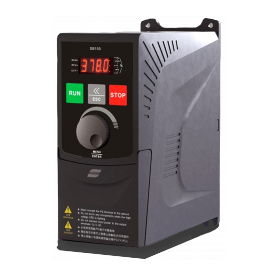
4 Operation and commissioning 4 Operation and commissioning 4.1 Operation and display 4.1.1 Functions of keypad The keypad is used to set or browse parameters, control operations, display error information and so on. The appearance of the keypad is as follows. Unit light Status light Operation key run... - Page 12 4 Operation and commissioning Indicators Unit Indicators Unit Indicators Unit r/min % Meanings of three indicators status Indicator Status Inverter state Standby state RUN indicator Stable run state Blinking Accelerating or decelerating state Both preset and current direction are forward REV indicator Both preset and current direction are reverse Blinking...
- Page 13 4 Operation and commissioning Parameter editing status In monitoring status, pressing enters the editing status, which contains second level menus: parameter group number→serial number in parameter group→parameter value. Pressing enters the next menu and 3 second, pressing returns to the previous menu(returns to monitoring status if at the first level menu). Pressing change the parameter group numbers, serial numbers in parameter group or parameter values.
-
Page 14: Quick And Optimize Commissioning
4 Operation and commissioning Alarm display status When the inverter detects the alarm information, the alarm code blinks. If there are multiple alarm signals, the alarm codes display alternately. The alarm information can be temporarily hidden by pressing . The alarm signal is automatically removed if normal state is recovered. The inverter does not stop in alarm display status. - Page 15 4 Operation and commissioning 4、Vibration damping: If the motor vibrates, increase this parameter gradually until the vibration disappears. Refer to F2-06.
-
Page 16: Parameter Table
5 Parameter table 5 Parameter table Note: In the “Change” column of the table below, “O” indicates the parameter can be changed in any state, “×” indicates the parameter is only changeable in running state, while “△” indicates the parameter is read only. F0 Basic Parameters Chan Name... - Page 17 5 Parameter table F1 Accel/decel, start, stop and jog parameters Name Setting range Default Page 0.1 ~ 3600.0s F1-00 Accel time 1 Acceleration time: time period over which the F1-01 Decel time 1 frequency rises by 50Hz. F1-02 Accel time 2 6.0s ○...
- Page 18 5 Parameter table Name Setting range Default Page F2-02 Auto torque boost level 0.0 ~ 100.0% 80.0% × F2-03 Slip compensation gain 0.0 ~ 300.0% 0.0% ○ Slip compensation 0.1 ~ 25.0s F2-04 1.0s × filtering time 0: No boost 1: Manual F2-05 Torque boost...
- Page 19 5 Parameter table Name Setting range Default Page keypad. ±5:External fault input F4-03 FWD terminal ±19:Reference frequency ±6:Fault reset switched to AI1 ±7:Jog forward ±20:Multi-PID select 1 ±8:Jog reverse ±21:Multi-PID select 2 ±9:Coast stop / ± 22 : Wobble frequency Operation disabled injection ±10:UP/DOWN...
- Page 20 5 Parameter table Name Setting range Default Page detection signal ±10:Process PID sleep ±4: Fault output ±11: Wobble frequency ±5: Undervoltage upper/lower limit lockout ±12: Feedback exceed upper ±6: Fault auto-reset limit alarm F5-01 T1 relay output ±13:Feedback low lower limit alarm.
- Page 21 5 Parameter table Name Setting range Default Page 1:Operating 7: PID reference value frequency 8: AI1 2:Reference 9: AI2 frequency 11: UP/DOWN value F6-10 AO function selection 3: Output current 12: DC bus voltage ○ 4: Output voltage 5: Output capacity 6:PID feedback value...
- Page 22 5 Parameter table Name Setting range Default Page 0.00 ~ 100.00% , Note : 100.00% sleeping F7-17 Awaken deviation 100.00% ○ invalid F7-18 Awaken delay time 0.500s 0.000~60.000s ○ Feedback exceed upper 50.0~200.0% F7-19 120.0% ○ limit alarm value Feedback exceed upper 0.0~100.0% F7-20 limit hysteresis loop...
- Page 23 5 Parameter table Name Setting range Default Page 0: No action 1:alarm Analog input Fb-02 2:alarm,press F0-00 × disconnection action 3:Coast to a stop, with an Er.Aco alarm 0: No action 1:only input 2:only output 3: Fb-03 Phase lose protection ×...
- Page 24 5 Parameter table Name Setting range Default Page Monitored parameter -1 ~ 17 FC-05 ○ 1(run) -1 indicates empty,0 ~ 17 indicate FU-00 ~ Monitored parameter FC-06 FU-17 ○ 2(run) Monitored parameter FC-07 ○ 3(run) FC-08 Speed display coefficient 0.001 ~ 10.000 1.000 ○...
- Page 25 5 Parameter table Name Description 0: No fault 11. PLo: Output phase loss ocb: Momentary 12. FoP: Power device protection overcurrent at start 13. oHI: Inverter overheating 2. ocA: Overcurrent in 14. oLI: Inverter overload accel 15. oLL: Motor overload 3.
- Page 26 5 Parameter table Name Description Operating frequency at 3rd last Min. unit:0.01Hz FP-22 fault Reference frequency at 3rd last Min. unit:0.01Hz FP-23 fault FP-24 Output current at 3rd last fault Min. unit:0.1A FP-25 Output voltage at 3rd last fault Min. unit:0.1V FP-26 Output capacity at 3rd last fault Min.
- Page 27 5 Parameter table Name Description FU-03 Load current percentage Inverter rated current=100%,Min. unit:0.1% FU-04 Output voltage Min. unit:0.1V FU-05 Operating speed Min. unit:1r/min FU-06 Reference speed Unit indicator blinks,Min. unit:1r/min FU-07 DC link voltage Min. unit:0.1V FU-08 Output capacity Min. unit:0.1kW FU-09 Operating line speed Min.
-
Page 28: Troubleshooting
7 Troubleshooting 7 Troubleshooting 7.1 Faults and remedies Fault code Fault type Possible causes Remedies Inter-phase grounding Check the motor and wiring short-circuit inside the motor or between wirings Overcurrent at start E.ocb(1) Inverting module failed Call us Voltage overhigh at start Check the setting of “torque boost”... - Page 29 7 Troubleshooting Fault code Fault type Possible causes Remedies Input phase loss Input the input power and wiring Input power phase loss Check the wiring Three input phases imbalanced Check input voltage Input phase loss E.PLI(10) Serious oscillation of output Adjust parameters to eliminate the oscillation Loss of output ( U, V or W)
-
Page 30: Alarms And Remedies
7 Troubleshooting Fault code Fault type Possible causes Remedies Motor stalls or load changes Correctly set F3-02、F3-05、Fb-00 suddenly and greatly V/F curve improper Check the load Loose wiring or components Check and rewire inside the inverter Current test error failed current sensor or circuit Call us E.ccF(18)... -
Page 31: Operation Faults And Remedies
7 Troubleshooting 7.3 Operation faults and remedies Fault Description Possible causes Remedies Poor contact of the keypad One key or all Check the connecting wire or call us connecting wire No key-press keys have no Key(s) damaged response response Replace the keypad key pressing The parameters are read-only Parameters... -
Page 32: Maintenance And After-Sale Service
8 Maintenance and After-sale Service 8 Maintenance and After-sale Service DANGER 1. Only professionally trained persons can disassemble and repair the inverter and replace its parts. 2. Make sure the power supply of the inverter is cut off, the high-voltage indicator goes out and the voltage between DC+and DC-is less than 36V before checking and repairing the inverter, otherwise there may be a risk of electric shock. -
Page 33: Replacement Of Parts
In the event of any abnormality arising in operation, check and adjust the inverter as per the user’s manual. In case any fault occurs, promptly contact the supplier, the local electrical engineering agent of Hope-Senlan Technologies Corporation or our headquarters. We will rectify any fault for free that arises from manufacturing... - Page 34 8 Maintenance and After-sale Service and design within the warranty period. For a rectification beyond the warranty period, we will charge the user as required at a reasonable rate.
Need help?
Do you have a question about the SB150 Series and is the answer not in the manual?
Questions and answers