
Related Manuals for Senlan SB200 Series


Summary of Contents for Senlan SB200 Series
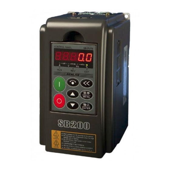
- Page 1 SENLAN INVERTER USER’S MANUAL SB200 Series Inverter High Performance General Space Verctor Control Input: 3 Phase 400v class Capacty:1.5 ~ 400kw Version 1.3 Hope Senlan Science & Technology Holding Corp., Ltd.
-
Page 2: Table Of Contents
Table of Contents PREFACE ................................1 1. NOTES ON SAFETY ..........................3 1.1. Notes on Safety..............................3 1.2. Caution:................................4 2. PRODUCT SPECIFICATION ......................8 2.1. Universal Technical Specification of SB200 Inverter Series ................8 2.2. Specification of the Inverter Series .......................10 3. - Page 3 6.8 F7: PID Parameters............................105 6.9. F8: Dedicated Water Supply Functions ....................... 111 6.10. F9: Time Management (Applicable to LCD Control Panel Only)............123 6.11 Fb: Protection Functions and Advanced Inverter Settings .................126 6.12 FC: Keyboard Operation and Display Settings ..................135 6.13 FF: Communication Parameters .........................138 6.14 FP: Fault Lists.............................147 6.15 FU: Data Monitoring ..........................149 7 SOLUTIONS TO FAULTS AND ABNORMALITIES...
-
Page 5: Preface
Preface Preface Thank you for selecting Senlan SB200 frequency inverter series. SB200 series integrate the optimized high-performance space vector control VVVF algorithm which supports numerous advanced functions, e.g. auto torque boost, slip compensation, oscillation suppression, tracking startup, stall prevention, precise deadband compensation, auto voltage stabilization, process identification and auto carrier frequency adjustment. - Page 6 Bar Code Rated Power: 15kw SLANVERT Hope Senlan Science & Technology Holding Corp., ltd Definition of Safety ID Markings Any safety-specific content of this manual may use the following markings for identification. The user is required to follow the instructions of the content identified with safety markings.
-
Page 7: Notes On Safety
Notes on Safety 1. Notes on Safety 1.1. Notes on Safety (1) Installation The inverter must not be installed at places with combustibles or in the vicinity of combustibles; otherwise there may cause fire. The inverter must not be installed in an environment exposed to flammable gases; otherwise There may cause explosion. -
Page 8: Caution
(2) Motor and Electrical Load Comparison with Line Frequency Operation The SB200 series are PWM voltage inverters with a certain level of harmonics in output voltage. Compared with a line frequency power supply, the voltage loss, temperature rise and noise generated by a working motor are slightly higher. - Page 9 Notes on Safety a prolonged constant-torque low-speed operation is required, a variable-frequency motor must be selected, or forced air cooling be provided. Motor Overload Protection When an adapted motor is used, the inverter can provide overload protection for the motor. If the motor does not match the rated inverter capacity, adjust the parameters for protection, or take any other protection measure to ensure safe motor operation.
- Page 10 Notes on Safety Contactor, etc. Installed at the Output Terminal of the Inverter If installation of contactors, etc. is required between the output terminal and the motor, please ensure that make-break operations are conducted when the inverter has no power output; otherwise the inverter may be damaged.
- Page 11 Notes on Safety increment of one degree Celsius. Also, forced external heat dissipation must be provided. 2) At 1,000m above sea level, the thinner air will deteriorate the heat dissipation effect of the inverter. Therefore, the inverter must be derated by 1% for every increment of 100m. 3) When the set carrier frequency exceeds the factory settings, the inverter must be derated by 5% for every increment of 1kHz.
-
Page 12: Product Specification
Product Specification 2. Product Specification 2.1. Universal Technical Specification of SB200 Inverter Series Item Description 3-phase, 380V; 50/60Hz Rated Voltage/Frequency Input Voltage: 320-420V; voltage unbalance:<3 % ; Range frequency: 47-63Hz Output Voltage 3-phase; 0v-input voltage; error: below 5% Output Frequency 0.00-650.00Hz Overload Capacity 110% of rated current;... - Page 13 Product Specification Item Description Multiple water supply modes: fire water control, water injection control, clean water pool inspection, Water Supply Mode wastewater pool inspection, drainage pump control, sleeping, pump change at regular intervals and pump overhaul Custom Menu 30 user parameters can be customized Parameter display different from the factroy settings Change of Parameter Display is supported...
-
Page 14: Specification Of The Inverter Series
Product Specification 2.2. Specification of the Inverter Series Refer to the following table for the ratings of the SB200 inverter series: Common Application Heavy Load Application (110%I every 10 minutes on (150%I every 10 minutes on Rated every minute) every minute) Model No. - Page 15 Product Specification 数字给定频率 37.00Hz 普通运行给定 返回 编辑 SB200 An Outline Drawing of the Inverter Series (SB200-1.5T4—5.5T4) (Installable with a standard DIN Guide Rail) SB200 An Outline Drawing of the Inverter Series (SB200-7.5T4—22T4)
- Page 16 Product Specification SB200 An Outline Drawing of the Inverter Series (SB200-30T4 and above)
- Page 17 Product Specification Refer to the following table for the overall dimension and weight of the SB200 inverter series: Weight Model No. (mm) (mm) (mm) (mm) (mm) (mm) (mm) (kg) SB200-1.5T4 87.5 Φ4.5 SB200-2.2T4 SB200-4T4 Φ4.5 SB200-5.5T4 SB200-7.5T4 Φ5.5 - SB200-11T4 SB200-15T4 Φ7 -...
-
Page 18: Installation And Wiring
Installation and Wiring 3. Installation and Wiring 3.1. Inverter Installation 1. The installation of the inverter may only be carried out by trained professionals. 2. Do not try to install a inverter if it is damaged or incomplete with any part; otherwise there may be hazards of fire or personal injuries. -
Page 19: Uninstallation/Installation Of Inverter Components
Installation and Wiring 3.2. Uninstallation/Installation of Inverter Components 3.2.1. Uninstallation/Installation of Cover and Control Panel 3.2.2. Uninstallation/Installation of Control Panel Uninstallation: Stick a finger into the hemispheric depression above the control panel, press the elastic flap on top of the panel and pull the panel out. Refer to the following drawing. Installation: Fit the fixing bayonet at the bottom of the panel into the dog at the bottom of the installation slot of the panel, press the upper side forward with a finger and release the finger after the panel is in place. - Page 20 Installation and Wiring 3.2.3. Installation of Control Panel on Cabinet Panel The user may remove the control panel from the SB200 inverter series and install it on the cabinet panel. The control panel and the inverter may be connected by an extension cord. The user may choose from the following two installation methods: Method 1: Direct Installation: ①...
-
Page 21: Wiring Of Inverter
Installation and Wiring ④ Plug the socket at one end of the extension cord into the control panel; plug the other end firmly into the corresponding socket on the circuit board of the inverter. Cover the inverter. Mounting box of Opening dim ensions the control panel Cabinet thickness: 1-1.5m m... - Page 22 Installation and Wiring 3.3.1. Wiring and Configuration of Main Loop Terminal Refer to the following drawing for the connection between the inverter and the peripherals: Power supply Air Circuit-Breaker Air circuit-breaker Cuts off power supply quickly in the event of an overcurrent of any downstream equipment Electromagnetic Electromagnetic Contactor...
- Page 23 Installation and Wiring SB200-18.5T4—22T4 SB200-220T4 SB200-30T4 SB200-250T4—280T4 SB200-37T4 SB200-315T4 1000 SB200-45T4—55T4 SB200-375T4—400T4 1500 Refer to the following drawing for fundamental wiring required for operation Applied to 30kW and above only; The installation of a DC Braking reactor requires the removal Braking resistor resistor of the jumper between P1...
- Page 24 Installation and Wiring The control cable, power cable and motor cable must be kept apart in order to prevent intercoupling interference. The three types of cable must be spaced at a sufficiently wide distance, especially when they are installed parallel to each other and run for a relatively long distance. Whenever the signal cable has to cross over the power cable, they must be vertical to each other.
- Page 25 Installation and Wiring Input Type Options: V: Voltage mode; mA: Current mode Input Type Options: V: Voltage mode; mA: Current mode Input Type Options: V: 0-10V (voltage signal); mA: 0/4-20mA (current signal) Input Type Options: V: 0-10V (voltage signal); mA: 0/4-20mA (current signal) Refer to the following tables for the layout of terminals on the control panel: 1TA 1TC 1TB 2TA 2TC 2TB 3TA 3TB 4TA 4TB 5TA 5TB...
- Page 26 Installation and Wiring Terminal Terminal Name Function and Description Technical Specification Code Function options: Refer to the Multifunctional Current mode: 0—20mA; load: description of Parameters F6-27 Analog Output 1 ≤500Ω and F6-31 Multifunctional Voltage mode: 0—10V; output: Select the voltage/current output Analog Output 2 10mA modes via Jumpers CJ4 and CJ5...
-
Page 27: Electromagnetic Interference Control Methods
Installation and Wiring Terminal Terminal Name Function and Description Technical Specification Code Output Terminal of Relay 5 (1) Wiring of Analog Input Terminal In a remote operation supported by analog signals, the control cable between the operation device and the inverter must be less than 30m. As analog signals are very vulnerable to interference, the analog control cables must be separately installed away from the strong current loop, relay loop and contactor loop. - Page 28 Installation and Wiring Loop equipment. If the equipment is not earthed, there will be fewer misoperations. In cases where the peripherals and the inverter share the same power supply, the interference generated by the inverter will be transmitted along the power cable in a reversed direction and cause misoperations of other equipment in the same system.
- Page 29 Installation and Wiring Refer to the following drawing for the path of leakage current: Wire-to-wire distributed capacitance Inverter Motor Earth distributed Earth distributed capacitance of the capacitance of Earth Leakage Current Leakage currents may leak into not only the inverter system, but also into other devices via the earth wire.
-
Page 30: Inverter Operation And Trial Operation
Inverter Operation and Trial Operation 4. Inverter Operation and Trial Operation 4.1. Inverter Operation and Display 4.1.1. Functions of Control Panel The control panel is the inverter component that receives a command or displays parameters. Parameters may be set up or checked via LED control panels, such as SB-PU70 (Standard), SB-PU03 and SB-PU70E or LCD control panels (e.g. - Page 31 Inverter Operation and Trial Operation Execution of a command STOP/RESET Shutdown and fault reset Refer to the following units of measurement for the combinations of different indicator lamps: Display Unit Description No unit or non-displayable unit (such as ℃, r/min Unavailable N, rad/s) r/min...
- Page 32 Inverter Operation and Trial Operation Both the direction settings and the present rotation Distinguished direction are clockwise Both the direction settings and the present rotation Illuminated direction are anticlockwise The setup direction and the present running direction are Flashing not the same Distinguished Control status of the control panel Illuminated...
- Page 33 Inverter Operation and Trial Operation 4.1.2. Display Status and Operation of Control Panel The control panel of the SB200 inverter series has the following display statuses: monitoring status (including standby monitoring and operation monitoring), parameter editing status, and fault status, alarm status, etc.
- Page 34 Inverter Operation and Trial Operation When FC-00 is set up as 1 (user parameters are displayed only) or 2 (parameters other than factory parameters are displayed only), the top hierarchy will not be displayed. This is intended to facilitate user operations. Password Verification If a user password has been set up, enter the password verification status before entry into the parameter editing status.
-
Page 35: Initial Energization
Inverter Operation and Trial Operation The results of the comparison comply 4.2. Initial Energization Wiring operations must be conducted as per the technical requirements of 3.3. Wiring of Inverter of this manual. Check and confirm the wiring and power supply. Then close the air circuit-breaker for the AC power supply on the input side of the inverter. - Page 36 Inverter Operation and Trial Operation 7. Parameters on Motor Nameplate: Rated power, number of poles, rated current and rated rotation speed. Refer to Page 51 for details. 8. Motor Overload Protection: For details, refer to Fb-00: Motor Heat Dissipation Conditions, Fb-01: “Motor Overload Protection Value”...
-
Page 37: Lists Of Function Parameters
Lists of function parameters 5. Lists of Function Parameters NOTE: Modification: “○” means that both the standby status and the operating status can be changed. “×” means that only the operating status can not be changed. “△” means “Read only”. F0: Basic Parameters Param Factory... - Page 38 Lists of function parameters Para Factory Modifi Name Setting Range and Description meter Settings cation Units digit: Storage option on Power Failure 0: Stores the main frequency settings modified by pressing or by communication to F0-00 upon poweroff 1: Does not store the main frequency settings modified pressing communication upon poweroff...
-
Page 39: F1: Acceleration/Deceleration, Startup, Shutdown And Jog Parameters
Lists of function parameters Para Factory Modifi Name Setting Range and Description meter Settings cation 11: Initialization Parameter F0-11 22: Initialization applicable to all parameters but × Initialization communication parameters 11: Parameters are uploaded from the inverter to the Parameter panel Copying 22: Parameters are downloaded from the panel to the... - Page 40 Lists of function parameters Factory Parameter Name Setting Range and Description ificat Page settings 0.0—3,600.0s Inapplicable when F8-00 is F1-10 Startup Delay Time 0.0s ○ not “0” 0: Startup at the startup frequency 1: DC braking comes before startup at the F1-11 Startup Mode ×...
-
Page 41: F2: V/F Control Parameters
Lists of function parameters F2: V/F Control Parameters Paramete Factory Name Setting Range and Description ificat Page settings 0: Custom 1: Linear 2: V/F Curve 1 (Torque lowering) F2-00 V/F Curve Settings 3: V/F Curve 2 (Torque lowering) 4: V/F ×... -
Page 42: F3. Motor Parameters
Lists of function parameters Paramete Factory Name Setting Range and Description ificat Page settings 0.0%—F2-19; F2-21 V/F Voltage V1 0.0% × F2-13 is taken as 100% F3. Motor Parameters Factory Parameter Name Setting Range and Description ificat Page settings Depend on F3-00 Rated Power 0.40—500.00kW... - Page 43 Lists of function parameters Paramete Factory Name Setting Range and Description ificat Page settings water pool analog frequency Functions of Digital ±7:Acceleration/decele settings Input Terminal X8 F4-07 ration time option 2 ±41:Acceleration/decel (Extension Terminal) ±8: Multi-PID Option eration disabled ±42: Switching of Functions of Digital ±9: Multi-PID Option command...
-
Page 44: F5: Settings Of Digital Output And Relay Output
Lists of function parameters Paramete Factory Name Setting Range and Description ificat Page settings 0: Single-wire mode (startup/shutdown) 1: Two-Wire Mode 1 (anticlockwise) 2: Two-Wire Mode 2 (startup/shutdown and direction) Terminal Working F4-13 3: Two-Wire Mode 3 (startup/shutdown) × Mode 4: Three-Wire Mode 1 (clockwise/anticlockwise and shutdown) 5: Three-Wire Mode 2 (operation, direction and... - Page 45 Lists of function parameters Factor Paramete Name Setting Range and Description Page ificat setting Functions of ±1: Inverter in operation ±32: Motor #5 in Digital Output ±2: Frequency attained variable-frequency F5-01 Terminal ±3: Output of Monitor 1 operation Y2/PFO/Pulse ±4: Output of Monitor 2 ±33: Motor #5 in Frequency Output ±5: Output of Monitor 3...
- Page 46 Lists of function parameters Factor Paramete Name Setting Range and Description Page ificat setting ±22: PC digital quantity 1 ±51: Indication for sleeping ±23: PC digital quantity 2 operation ±24: Motor #1 in ±52: Water shortage in variable- suction pool frequency operation ±53: Abnormal closing ±25: Motor #1 in line...
-
Page 47: F6: Terminals Settings For Analog Quantities And Pulse Frequency
Lists of function parameters Factor Paramete Name Setting Range and Description Page ificat setting Detection Lag F5-18 Value of Monitor 5.00 ○ Detected Value of F5-19 60.00 ○ Monitor 3 Detection Lag F5-20 Value of Monitor 5.00 ○ Paramete Factory Name Setting Range and Description ificat... - Page 48 Lists of function parameters Paramete Factory Name Setting Range and Description ificat Page settings AI1 Min. Input F6-00 0.00% ○ Analog Quantity -100.00-100.00% AI1 Max. Input Analog F6-01 100.00% ○ Quantity Set Value/Feedback Value Corresponding F6-02 0.00% ○ -100.00-100.00% with AI1 Min. Input NOTE: Frequency settings must be based on the Analog Quantity max.
- Page 49 Lists of function parameters Paramete Factory Name Setting Range and Description ificat Page settings -100.00-100.00% Set Value/Feedback NOTE: Frequency settings must be based on the F6-20 Value of AI3 Min. Input 0.00% ○ max. frequency as a reference; the PID set Analog Quantity value/feedback value must be represented as the percentage of the PID reference values...
- Page 50 Lists of function parameters Paramete Factory Name Setting Range and Description ificat Page settings PFI Frequency F6-36 0-50,000Hz ○ Corresponding with 0% F6-37 PFI Filter Time 0.000-10.000s 0.100s ○ Y2/PFO Function 0—13; same as AO1 function option F6-27 F6-38 ○ Options 14: Digital output PFO Output Pulse...
-
Page 51: F7: Pid Parameters
Lists of function parameters F7: PID Parameters Paramete Factory Name Setting Range and Description ificat Page settings 0: PID control is not selected 1: PID control is selected 2: PID is selected for frequency settings PID Control Function F7-00 × Options modification 3: PID control is selected for constant pressure... -
Page 52: F8: Dedicated Water Supply Functions
Lists of function parameters Paramete Factory Name Setting Range and Description ificat Page settings F7-12 Sampling Period 0.001—10.000s 0.010s ○ F7-13 Ultimate Deviation 0.0—20.0%; PID settings is taken as 100% 0.0% ○ Set Value F7-14 0.00—20.00s 0.00s ○ Increase/Decrease Time PID Adjustment 0: Positive action F7-15... - Page 53 Lists of function parameters Paramete Factory Name Setting Range and Description ificat Page settings Units digit: Number of variable frequency cyclical switchover pumps: 1~5 Tens digit: Number of auxiliary pumps : 0~4 Hundreds digit: Startup mode of auxiliary pump 0: Direct startup 1: Started by soft starter Thousands digit: Sleeping and sleeping pump options...
- Page 54 Lists of function parameters Paramete Factory Name Setting Range and Description ificat Page settings Waste Water Pool Lower F8-08 30.0% ○ Level Limit Signal 0.0~100.0% Waste Water Pool Upper F8-09 80.0% ○ Level Limit Signal Increasing Pump F8-10 30.0s ○ Coming Frequency 0.0~600.0s Increasing...
- Page 55 Lists of function parameters Paramete Factory Name Setting Range and Description ificat Page settings Rated Current of Small model No. × F8-35 Sleeping Pump F8-36 Trial Working frequency 1.00~F0-07“Upper Frequency Limit” 25.00 Hz ○ 111 Sleeping pump in trial operation 222 Drainage pump in trial operation 331~335 Pumps #1~#5 in trial operation at Pump Trial Operation...
- Page 56 Lists of function parameters Paramete Factory Name Setting Range and Description ificat Page settings 00~22 Units digit: Number of cyclical switchover Standby Pump Number ○ F8-51 pumps on standby Settings Tens digit: Number of auxiliary pumps on standby...
-
Page 57: F9: Time Management (Applicable To Lcd Control Panel Only)
Lists of function parameters F9: Time Management (Applicable to LCD Control Panel Only) Paramete Factory Name Setting Range and Description ificat Page settings Time Settings at Point F9-00 0.00 ○ Time Settings F9-01 3.00 ○ Point T2 Time Settings at Point F9-02 6.00 ○... -
Page 58: Fb: Protection Functions And Advanced Inverter Settings
Lists of function parameters Paramete Factory Name Setting Range and Description ificat Page settings Functions Virtual × F9-19 Digital Input 4 Fb: Protection Functions and Advanced Inverter Settings Paramete Factory Name Setting Range and Description Page ificat settings 0: Conventional motor Motor Heat Dissipation Fb-00 1:Variable frequency motor or complete with a... - Page 59 Lists of function parameters Paramete Factory Name Setting Range and Description ificat Page settings protection 0: No action 1: alarm 2: fault and free shutdown Thousands digit: Parameter storage failure action options 0: Alarm 1: Fault and free shutdown 0: Invalid Acceleration 1: Valid;...
- Page 60 Lists of function parameters Paramete Factory Name Setting Range and Description ificat Page settings Failure, Self-Reset and Operation Suspension Poweron Self-Restart 0: Disabled Fb-26 ○ Enabled 1: Enabled Braking Unit Working Fb-27 620~720V 680V ○ Point 0: Auto modulation Fb-28 Modulation Mode ○...
- Page 61 Lists of function parameters Paramete Factory Name Setting Range and Description ificat Page settings Fb-43 ~ Fb-60 Retained - - -...
-
Page 62: Fc: Keyboard Operation And Display Settings
Lists of function parameters FC: Keyboard Operation and Display Settings Paramete Factory Name Setting Range and Description ificat Page settings Display Parameter 0: All parameters 1: User parameters FC-00 ○ Options Those different from factory settings Units digit: Auto key lock 0: Unlocked 1: All locked 2: All locked except... -
Page 63: Ff: Communcation Parameters
Lists of function parameters Paramete Factory Name Setting Range and Description ificat Page settings Operation Monitoring FC-09 ○ Parameter 1 Operation Monitoring -1~50 FC-10 ○ Parameter 2 -1 means void; 0~50 mean FU-00~FU-50 which are used to select monitoring parameters Operation Monitoring FC-11... -
Page 64: Fn: Factory Settings
Lists of function parameters Para Factory Name Setting Range and Description ificat Page meter Setting 9:500,000bps FF-03 Local IP Address 0~247 × Communication Timeout FF-04 0.1~600.0s 10.0s ○ Detection Time FF-05 Local Response Delay 0~1,000ms ○ 0: No action 1: Alarm 2: Fault and free shutdown Communication Timeout FF-06... -
Page 65: Fp: Fault Logs
Lists of function parameters FP: Fault Logs Paramete Name Setting Range and Description Pages 16. EEF: External fault 17. oLP: Motor overload ULd: Inverter underload 0. No fault 19.cnF: Main loop 1. ocb: Instantaneous startup contactor fault overcurrent 20. cno: Water supply 2.ocA: Accelerated operation... - Page 66 Lists of function parameters Paramete Name Setting Range and Description Pages Pump Status 2 during FP-10 Tens digit: Drainage pump Units digit: Sleeping pump Last Fault Type of Last but One FP-11 The same designation as FP-00 Fault Cumulative Operation FP-12 Time during Last but Min.
-
Page 67: Fu: Data Monitoring
Lists of function parameters FU: Data Monitoring Parame Page Name Setting Range and Description FU-00 Working frequency Motor rotation frequency; min. unit: 0.01Hz FU-01 Frequency Settings Unit indicator lamp flashes; min. unit: 0.01Hz FU-02 Output Current Min. unit: 0.1A Load Current FU-03 The rated inverter current is taken as 100%;... - Page 68 Lists of function parameters Digital Output Tens digit: Y2 Units digit: Y1 FU-27 Terminal Status 0: OFF 1: ON Ten thousands digit: T5 Thousands digit: T4 Hundreds digit: Relay Output Terminal FU-28 Tens digit: T2 Unit digit: T1 Status 0: OFF 1: ON Ten thousands digit: X11 Thousands digit: X10...
-
Page 69: Details About Function Parameters
Details about Function Parameters 6. Details about Function Parameters 6.1. F0: Basic Parameters Factory 50.00Hz Modification F0-00 Digital Frequency Settings ○ Settings Setting 0.00Hz~F0-06“Max. Frequency” Range Main Setting Channel Factory F0-01 Modification ○ Normal Operation Settings 0: F0-00 adopts digital settings via the control panel adjustment ( 1: Communication settings;... - Page 70 Details about Function Parameters modified. A jogging command means that a keyboard jogging via panel control is effective, or that a digital input 14 “Clockwise Jogging” or 15 “Anticlockwise Jogging” via terminal control is effective. The final frequency settings will be subject to F0-07 “Upper frequency limit” and F0-08 “Lower frequency limit”.
- Page 71 Details about Function Parameters Factory F0-03 Frequency Setting Retention Mode Modification ○ settings Units digit: 0: Upon poweroff, the main frequency settings modified via Poweroff storage communication or will be stored to F0-00 option 1: Upon poweroff, the main frequency settings modified via communication or will not be stored Setting...
- Page 72 Details about Function Parameters It is used for calibration for a frequency setting by analog input or PFI. F0-07 “Upper Frequency Limit”/F0-08 “Lower Frequency Limit”: Limits for the final frequency settings. Factory F0-09 Direction Lock Setting Modification ○ Both clockwise Setting direction 1: Clockwise direction...
-
Page 73: F1: Acceleration/Deceleration, Startup, Shutdown And Jog Parameters
Details about Function Parameters Parameter copying is a very useful function on occasions where more than one inverter adopts the same settings. It is inadvisable to use the downloading function between inverters of different power ratings. This function only applies to control panels integrating parameter coping (SB-PU70E and SB-PU200). - Page 74 Details about Function Parameters Depend Factory F1-03 Deceleration Time 2 inverter Modification ○ Settings model 0.1~3600.0s Acceleration time: The time required to increase the frequency by 50Hz Setting Deceleration time: The time required to decrease the frequency by 50Hz Range NOTE: Factory settings are 6.0s for 22kW inverter series and below and 20.0s for 30kW and above Deceleration...
- Page 75 Details about Function Parameters Factory F1-06 Jog Frequency Setting 5.00Hz Modification ○ Setting 0.10~50.00Hz Range Depend Factory Modification ○ F1-07 Jog Acceleration Time Setting inverter model Depend Factory F1-08 Jog Deceleration Time Setting inverter Modification ○ model 0.1~60.0s NOTE: Factory settings for jog acceleration/deceleration time are 6.0s for 22kW Setting inverter series and below Range...
- Page 76 Details about Function Parameters When selecting the water supply mode for the inverter, F1-10 “startup delay time” will be ineffective and the operation command will be immediately executed. Factory Modification × F1-11 Startup Mode Setting Setting 0: Startup from the startup frequency 1: DC braking comes before startup from the Range startup frequency...
- Page 77 Details about Function Parameters Failure, Self-Reset and Operation Suspension”. Refer to the following figures for startup/shutdown DC braking: Output frequency Shutdown/DC braking frequency Startup frequency Time Output frequency Shutdown DC braking frequency Startup DC Time braking current Shutdown DC Shutdown DC Startup DC braking time braking waiting time braking time...
-
Page 78: F2: V/F Control Parameters
Details about Function Parameters become lower until the inverter changes into the standby mode when F1-17 “Shutdown/DC Braking Frequency” is actuated. When F1-16=1, the inverter will have a free shutdown. The inverter will lock the output and the motor will slide freely to a shutdown. But if it is a jog shutdown or an emergency shutdown, the deceleration-mode shutdown will still be effective. - Page 79 Details about Function Parameters efficiency. Refer to the following figures for linear V/F curves and V/F curves (torque lowering): Voltage Basic frequency; Max. output voltage th power 1:1.0 th power 2:1.2 th power 3:1.5 th power 4:1.7 th power 5:2.0 th power 6:3.0 Frequency...
- Page 80 Details about Function Parameters output appropriate voltage. This function can ensure larger output torque under heavy loads and smaller output currents under zero load. Tracking startup, auto torque elevation and slip compensation involve some motor parameters. Please confirm that these parameters conform to the parameters on the nameplate. Voltage Basic frequency;...
- Page 81 Details about Function Parameters × Number of poles÷120) If the motor oscillates in the course of slip compensation, tune up F2-06 “Filter time of slip compensation”. Depend Factory inverter Modification ○ F2-09 Vibration Dampening Settings model Setting 0~200 Range The oscillation of a motor under a zero or light load may be controlled by adjusting this parameter.
- Page 82 Details about Function Parameters Setting 0: Inapplicable 1: Applicable Range Auto Energy-Saving Options: The output voltage is automatically adjusted to minimize the load current and motor loss at a constant rotation speed. This function is especially effective for such loads as fans and pumps with torque lowering characteristics. Refer to the following figures: Current Heavy load Small load...
-
Page 83: F3: Motor Parameters
Details about Function Parameters Factory F2-18 V/F Frequency F2 Setting 0.00Hz Modification × Setting F2-20“V/F Frequency F1”~F2-16“V/F Frequency F3” Range Factory Setting Modification × F2-19 V/F Voltage V2 0.0% F2-21“V/F Frequency V1”~F2-17“V/F Frequency V3”; F2-13 “max. output voltage” is Setting Range taken as 100%... -
Page 84: F4: Digital Input Terminals And Multi-Speed
Details about Function Parameters Depend F3-02 Rated Current Factory Settings inverter Modification × model Setting 0.5~1200.0A Range Factory Settings 50.00Hz Modification × F3-03 Rated Frequency Setting 1.00~650.00Hz Range Depend F3-04 Rated Rotation Speed Factory Settings inverter Modification × model Setting 125~40000r/min Range Prior to the operation of the inverter, input Parameters F3-00 ~... - Page 85 Details about Function Parameters Factory Modification × F4-11 Functions of FWD Terminal Factory Modification × F4-12 Functions of REV Terminal Setting Refer to the following table for definitions of digital input functions Range Table of Definitions of Digital Input Functions (The same function must not be selected for any two different digital input terminals) 0: Connection to the following signals ±20: UP/DOWN: Down...
- Page 86 Details about Function Parameters ±55: Priority pump startup option 1 ±56: Priority pump startup option 2 ±57: Priority pump startup option 3 A negative value means that the terminal input is a high level or that the rising edge is effective. A positive value means that the .terminal input has a low level, or that the falling edge is effective.
- Page 87 Details about Function Parameters Multi-PID Option Multi-PID Option Multi-PID Option 3 PID Settings Selected Depend on F7-01 “Channel Setting Options” F7-22 “Multi-PID Setting 1” F7-23 “Multi-PID Setting 2” F7-24 “Multi-PID Setting 3” F7-25 “Multi-PID Setting 4” F7-26 “Multi-PID Setting 5” F7-27 “Multi-PID Setting 6”...
- Page 88 Details about Function Parameters operation. 26: Check of Contactor 3K1: Used to check the contactor for Pump #3 variable frequency operation. 27: Check of Contactor 3K2: Used to check the contactor for Pump #3 line frequency operation. 28: Check of Contactor 4K1: Used to check the contactor for Pump #4 variable frequency operation.
- Page 89 Details about Function Parameters input. This function is very useful in cases where electromagnetic interference makes analog input commands susceptible to changes. Refer to the following figures: Analog input Time Digital Input 40 Analog reference frequency hold Time Reference frequency Time 41:Acceleration/Decelearation Disabled:...
- Page 90 Details about Function Parameters Terminal #1(F3-02) #4 (F8-32) (F8-30) (F8-31) Motor Option 1 Motor Option 2 In the constant-pressure water supply mode, the rated current will be automatically selected for the corresponding pumps to achieve overload protection values. When the digital input is set as 43 and 44, the corresponding function is Pump Disabled Options 45~49: Pump Disabled: After the corresponding water pump disablement signal is inputted, an overhaul of an abnormal pump shutdown will be carried out.
- Page 91 Details about Function Parameters 0: Single-wire mode (startup/shutdown) 1: Two-Wire Mode 1 (Clockwise/Anticlockwise) Setting 2: Two-Wire Mode 2 (startup/shutdown and direction) Range 3: Two-Wire Mode (Startup/Shutdown) 4: Three-Wire Mode 1 (clockwise/anticlockwise and shutdown) 5: Three-Wire Mode 2 (Operation, direction and shutdown) Digital input commands: 37 “Three-wire mode shutdown command”, 38 “Internal virtual FWD terminal”...
- Page 92 Details about Function Parameters F4-1 Mode Name Operation Logic Diagram Three-Wire Mode 1 (Clockwise, Anticlockwise Three-Wire Mode Shutdown Command and Shutdown) B1: Stop Button (NORMALLY OFF) Internal Virtual FWD Terminal Digital input 37 B2: Clockwise Button (NORMALLY ON) “Three-Wire Internal Virtual REV Terminal B3: Anticlockwise Button (NORMALLY ON) Mode Shutdown...
- Page 93 Details about Function Parameters Factory ○ Modification F4-15 UP/DOWN Adjustment Settings Setting 0: Terminal 1:Terminal 2: Control panel 3: Control panel pulse Range Le vel mode pulse mode level mode mode Factory ○ F4-16 UP/DOWN Rated/Step Length 1.00 Modification Settings Setting 0.01~100.00;...
-
Page 94: F5: Digital Output And Relay Output Settings
Details about Function Parameters UP/Down Value UP/Down Value Time Time UP/Down UP/Down Increase Increase Time Time UP/Down UP/Down Decrease Decrease Time Time UP/Down Pulse-type Adjustment UP/Down Level-Type Adjustment Digital Input 21 “UP/DOWN CLEAR”: This signal is used to clear FU-17 “UP/DOWN Adjustment”... - Page 95 Details about Function Parameters Output Functions T10/Y7 Factory × F5-11 Modification Settings (Extension Output) Output Functions T11/Y8 Factory × Modification F5-12 Settings (Extension Output) Setting 0~59; refer to the following table of definitions of digital output functions Range Related Monitoring Parameters: FU-27, FU-28, FU-30 and FU-31(Digital Output Terminal Status) Table of Definitions of Digital Output Functions 0: Inverter ready for operation...
- Page 96 Details about Function Parameters 2: Frequency attained: The function is effective when the operating frequency is within the positive/negative detection width of the frequency settings. Refer to F5-13 on page 60 for details. 3~5: Output of Monitors 1, 2 and 3: Refer to F5-14 ~ F5-20 on Page 60 for details. 6: Fault output: An effective signal will be outputted if the inverter has a fault.
- Page 97 Details about Function Parameters supply, the signal is used to control the contactor (variable frequency operation) of Pump #2. 27: Motor #2 in line frequency operation: When the inverter is used for constant pressure water supply, the signal is used to control the contactor (line frequency operation) of Pump #2. 28: Motor #3 in variable frequency operation: When the inverter is used for constant pressure water supply, the signal is used to control the contactor (variable frequency operation) of Pump #3.
- Page 98 Details about Function Parameters sleeping operation. 52: Water shortage in suction pool: The pump will be shut down when there is a water shortage in the suction pool. The signal will be outputted for an alarm and a shutdown will follow. 53: Abnormal closing of contactor: When the programmable digital terminal is used for contactor detection, if the status of the contactor is detected to be uncompliant with the control logic, the signal will be outputted for an alarm and a shutdown will follow.
- Page 99 Details about Function Parameters 0:Working frequency, Output Detection 2: PID feedback value, Output Detection Mode 1 Mode 1 1:Working frequency; Output Detection 3: PID feedback value, Output Detection Mode 2 Mode 2 Factory F5-15 Detected value of Monitor 1 20.00 Modification ○...
- Page 100 Details about Function Parameters Factory F5-21 Terminal Y1 Closing Delay 0.00s Modification ○ settings Factory 0.00s Modification ○ F5-22 Terminal Y1 Opening Delay Settings Factory F5-23 Terminal Y2 Closing Delay 0.00s Modification ○ Settings Factory 0.00s Modification ○ F5-24 Terminal Y2 Opening Delay Settings Setting 0.00~650.00s...
-
Page 101: F6: Settings Of Analog Quantities And Pulse Frequency Terminals
Details about Function Parameters 6.7 F6: Settings of Analog Quantities and Pulse Frequency Terminals Factory Min. Input Analog F6-00 0.00% Modification ○ Quantity Settings Factory Max. Input Analog F6-01 100.00% Modification ○ Quantity Settings Setting Frequenc -100.00-100.00% Set Value/Feedback Value Factory F6-02 Corresponding with AI1 Min. - Page 102 Details about Function Parameters Factory Max. Input Analog Modification ○ F6-10 100.00% Settings Quantity Setting Frequenc -100.00~100.00% Value/Feedback Value Factory F6-11 Corresponding with AI2 Min. 0.00% Modification ○ Settings Input Analog Quantity Value/Feedback Value Factory Corresponding with AI2 Max. Modification ○...
- Page 103 Details about Function Parameters Set Value/Feedback Value of Factory F6-21 Max. Input Analog 100.00% Modification ○ Settings Quantity -100.00~100.00% Setting NOTE: Frequency settings must be based on the max. frequency as a reference; the PID Frequenc set value/feedback value must be represented as the percentage of the PID reference values Input Analog Quantity of AI3 Factory...
- Page 104 Details about Function Parameters When most applications have an analog input voltage of 0 ~ 10V/0 ~ 20mA in correspondence with the set value/feedback value of 0 ~ 100 % , the default factory settings can be directly applied. At this point, the input analog quantity at inflection point overlaps the min.
- Page 105 Details about Function Parameters 100% (F6-01,F6-03) F6-00 = - 100.00 Min. Input Analog Quantity F6-01 = 100.00 Max. Input Analog Quantity F6-02 = 0.00 Settings/feedback value corresponding with min. input analog quantity F6-03 = 100.00 (F6-00,F6-02) Settings/feedback value corresponding with max. input analog quantity F6-04 = -...
- Page 106 Details about Function Parameters 100% (F6-01,F6-03) F6-00 = 0.00 Min. Input Analog Quantity F6-01 = 100.00 Max. Input Analog Quantity F6-02 = 0.00 Settings/feedback value corresponding with min. input analog quantity F6-03 = 100.00 Settings/feedback value corresponding with max. input analog quantity F6-04 = 30.00 Input Analog Quantity of Inflection Point F6-05 = 0.00...
- Page 107 Details about Function Parameters Factory Modification ○ F6-31 AO2 Function Options Settings Factory Modification ○ F6-32 AO2 Type Options Settings 100.0 Factory Modification ○ F6-33 AO2 Gain Settings % Factory F6-34 AO2 Offset 0.00% Modification ○ Settings Setting All settings of AO2 are the same as those of AO1 Range Table of Definitions of Analog Output 0: Working Frequency (the max.
- Page 108 Details about Function Parameters Factory PFI Frequency Corresponding with F6-35 Setting 10000Hz Modification ○ 100% Factory PFI Frequency Corresponding with Setting Modification ○ F6-36 Setting 0~50000Hz Range Factory 0.100s Modification ○ F6-37 PFI Filter Time Setting Setting 0.000~10.000s Range The PFI function may be used to convert the input pulse frequency to a percentage for filtering. FU-16 “PFI”...
-
Page 109: F7: Pid Parameters
Details about Function Parameters Factory F6-42 PFO Duty Ratio Corresponding with 100% Setting 100.0% Modification ○ Factory F6-43 PFO Duty Ratio Corresponding with 0% Setting 0.0% Modification ○ Setting 0.0~100.0% Range PFO: The internal percentage signals are outputted as pulse frequency or duty ratio. Refer to the following figures: PFO frequency PFO duty ratio (%) - Page 110 Details about Function Parameters PID differential amplitude clipping limit PID upper amplitude clipping limit Differe- ntiator Adjust- Settings PID setting PID output Ultimate ment Ratio channel deviation charact- options eristics Integrator Feedback PID Lower amplitude clipping limit PID feedback channel Integral Preset options...
- Page 111 Details about Function Parameters 0: F7-04 1: AI1 2: AI2 3: AI3 4:UP/DOWNadjustment Setting 6:Communication Range 5: PFI 7:AI-AI2 8: AI1+AI2 9: Panel potentiometer settings Factory F7-02 Feedback Channel Option Modification × Settings 0: AI1 1: AI2 2: AI3 3: AI1 - AI2 4:AI1 +...
- Page 112 Range 2: Transition by deviation The SB200 series have two PID parameter systems: PID parameters 1 (F7-05/F7-06/F7-07) and PID parameters 2 (F7-08/F7-09/F7-10). Parameter switching is available for digital input 36 “PID Parameter Option 2”. Also, gradual transition switching is available according to the working frequency or the percentage of the deviation between the settings and the feedback value.
- Page 113 Details about Function Parameters time of the controlled object. Factory 0.0% Modification ○ F7-13 Ultimate Deviation Setting Setting 0.0~20.0%; PID settings are taken as 100% Range When the deviation between the set value and the feedback is smaller than the ultimate deviation, PID stops adjustment and the output remains unchanged.
- Page 114 Details about Function Parameters conditions, the rotational speed is required to be decreased (i.e. cooling control). Factory Modification × F7-16 Integral Control Options Settings Setting 0: No integral action 1: Integral action Range Factory 100.0% Modification ○ F7-17 PID Upper Amplitude Limit Settings Setting F7-18 “PID Lower Amplitude Limit”~100.0%...
-
Page 115: F8: Dedicated Water Supply Functions
Details about Function Parameters If the preset value maintenance time is set as zero, PID control will be conducted upon taking the preset value as the initial value of the integrator. It corresponds with the preload of PID and is used to improve the response speed at the startup stage. - Page 116 Details about Function Parameters pump will be quickly started at the preset acceleration time. At this point, the output frequency will not be set by the PID regulator. When F8-00, water level control is effective: In water level control mode, the inverter will enter the standby mode after receipt of execution commands and start up or shut down the water pump according to water level signals (digital inputs 52 and 53;...
- Page 117 Details about Function Parameters Number of auxiliary pumps: These are pumps working only at a line frequency. Startup mode of auxiliary pumps: “0” means direct startup. It is suitable for only pumps of a smaller power (30kW and below). “1” means startup by soft starter. A pump of a larger capacity must not be directly started at a line frequency;...
- Page 118 Details about Function Parameters Tens digit: Waste water pool signal options Units digit: Clean water pool signal options Setting 0: Water level signal is not subject to detection Range 1: Analog signal AI1 input 2: Analog signal AI2 input 3: Analog signal AI3 input 4: Digital signal input Factory Clean Water Pool Lower Level...
- Page 119 Details about Function Parameters 3phase 380V Water level SB200 Upper limit Water shortage Lower limit Transmitted out Time Actual Clean water pool pressure settings Upper water Pressure settings level limit F8-07 Water shortage level Lower water level limit Time Clean water pool signal detection Waste Water Pool Level Signals: Water level detection may be operated via a liquid level transducer or an external liquid level detector.
- Page 120 Details about Function Parameters 3-phase 380V SB200 Drainage pump control box Drainage Startup pump controller relay control Drainage pump Transmitted out Wastewater pool Clean water pool Upper water level limit Lower water level limit Wastewater pool signal detection Factory F8-10 Increasing Pump Time Delay 30.0s Modification...
- Page 121 Details about Function Parameters Setting 0.00~50.00Hz Range Increasing Pump Coming Frequency: If more pumps are needed after the output frequency reaches the upper frequency limit, the inverter will operate at the Increasing Pump Coming Frequency. This is intended to prevent a sudden pressure rise as a result of more pumps from causing pressure overshoot and oscillation.
- Page 122 Details about Function Parameters Setting 0.50~60.00s Range Auxiliary Starter Startup Time: Auxiliary starters are normally soft starters. In the case of a larger power auxiliary pump, soft starters are normally used for startup in order to prevent large impact currents caused by direct startup. Factory F8-18 Periodic Rotation Time...
- Page 123 Details about Function Parameters The sleeping function requires sleeping mode settings. If water consumption is small and only one pump is in variable frequency operation, the system will switch to the sleeping mode and the main pump will shut down when the working frequency is lower than the sleeping frequency ((F8-20) and the operation time exceeds the sleeping latency time (F8-21).
- Page 124 Details about Function Parameters Factory 20.00 F8-28 Min. Working Frequency of Pump #4 Modification ○ Settings Factory 20.00 Min. Working Frequency of Small Modification ○ F8-29 Settings Sleeping Pump Setting 1.00~F0-07 “Upper frequency limit” Range Min. Working Frequency of Pumps. The min. working frequency of Pumps F8-24~29 is the lower frequency limit of the corresponding pumps working at a variable frequency.
- Page 125 Details about Function Parameters Factory 25.00 Modification ○ F8-36 Trial Working frequency Settings Setting 1.00~F0-07“Upper Limit Frequency” Range Factory F8-37 Pump Trial Operation Modification × Settings Sleeping pump in trial operation Drainage pump in trial operation Setting Range 331~335 Pumps #1~#5 in trial 441~445 Pumps #1~#5 in trial operation operation at a variable frequency...
- Page 126 Details about Function Parameters Startup Sequence: When any number in “1 ~ 5” is selected, the pump to be first started will be directly selected. Startup Sequence: When “6” is selected, a motor disused for a relatively long time will be started to prevent rusting from disuse.
-
Page 127: F9: Time Management (Applicable To Lcd Control Panel Only)
Details about Function Parameters Factory Modification ○ F8-44 Pump #1 Disabled Settings Factory Modification ○ F8-45 Pump #2 Disabled Settings Factory F8-46 Pump #3 Disabled Modification ○ Settings Factory F8-47 Pump #4 Disabled Modification ○ Settings Factory Modification ○ F8-48 Pump #5 Disabled Settings Factory... - Page 128 Range Page 51 Time Management : The LCD control panel of the SB200 series has an inbuilt time module capable of configuration for 8 time slots. The configuration of time must ensure that T1 ≤ T2 ≤ T3 ≤ T4 ≤ T5 ≤ T6 ≤ T7 ≤ T8. When setting actions for each point in time, functions required to be outputted at a designated time may be assigned (In the case of a digital output or relay output, the digital output of the corresponding functions must be set as 18;...
- Page 129 Details about Function Parameters digital output terminal, a positive value means Output Transistor Y is connected and Output Transistor Y is disconnected. In the case of a relay output, a positive value means the relay is closed and a negative value means the relay is open. In the case of a virtual digital output: a positive value means the selection of a function and a negative value means the cancellation of a function.
-
Page 130: Fb: Protection Functions And Advanced Inverter Settings
Details about Function Parameters Examples: Refer to the following figures: F9-02= 6:00 T3Time Point settings F9-10= 8 Virtual digital input 1 effective F9-03= 8:00 T4Time Point settings F9-11= 3 Relay T1 closed F9-04=12:00 T5Time Point settings F9-12= -3 Relay T1 open F9-07=23:00 T8Time Point settings F9-15= -8... - Page 131 Details about Function Parameters Action Fb-01 Variable-frequency motor time (m ) Overload protection or conventional motor value(%) Motor overload with a separate fan protection value Cold startup Conventional motor Hot startup 100% 150% 200% 0.7 times rated Rated Rotation speed Motor current rotation speed rotation...
- Page 132 Details about Function Parameters Factory Underload Protection Detection Fb-08 1.0s Modification × Settings Time Setting 0.0~100.0s Range Motor Underload Protection: When the output current is lower than Fb-07 and is maintained for a time longer than the time settings of Fb-08, a response will be made according to the action mode set by Fb-06.
- Page 133 Details about Function Parameters Inverter Output Phase lack Protection: In the case of a inverter output phase lack, the motor will switch to single-phase operation and the current, torque and pulse will increase. Output phase lack protection can prevent damages to motors and mechanical loads. Output phase lack protection is ineffective in cases where the output frequency or current is very low.
- Page 134 Details about Function Parameters In the deceleration process, when Fb-16 “Overvoltage Stall Prevention Options” is effective and the DC busbar voltage exceeds Fb-17 “Overvoltage Stall Point”, the deceleration will be suspended until the DC busbar voltage drops to normal. After that, the deceleration process resumes.
- Page 135 Details about Function Parameters solutions may be adopted: Fb-18=0: In this case, an undervoltage is considered as a fault and a free shutdown will follow and a DC busbar undervoltage fault will be reported; Fb-18=1: In this case, the output will be locked and the drop in DC bus voltage slows down. If the voltage is restored within “Instantaneous Power Failure Time Allowance”...
- Page 136 Details about Function Parameters Fault Self-Reset: Faults in operation will be self-reset according to Fb-23 “Self-Reset Interval” and Fb-22 “Fault Self-Reset Frequency”. Restarts will also be possible. This function is intended to prevent trips caused by misoperation, instantaneous overvoltage of the power supply or external non-repetitive impacts.
- Page 137 Details about Function Parameters 0: Auto modulation (auto switching between continuous modulation and noncontinuous Setting modulation) Range 1: Continuous modulation The auto mode has much lower switching loss when switching to noncontinuous modulation, but its harmonics is larger than continuous modulation. Depend on Factory Fb-29...
- Page 138 Details about Function Parameters Setting 0: Disabled 1: Enabled Range Deadband compensation can reduce output harmonics and torque pulse. But deadband compensation must be disabled when the inverter is used for a power supply. Space Vector Angle Shutdown Factory Fb-33 Modification ×...
-
Page 139: Fc: Keyboard Operation And Display Settings
Details about Function Parameters Factory 0.00Hz Modification ○ Fb-40 Avoidance Frequency 3 Settings Modification 0.00~625.00Hz Width Avoidance Factory Fb-41 0.00Hz Modification ○ Settings Frequency 3 Modification 0.00~20.00Hz The avoidance frequency function is intended to protect the working frequency of the inverter from mechanic resonance points. - Page 140 Details about Function Parameters password is ineffective for these parameters, the modification of FC-00 requires the user password. FC-00 = 2: In order to facilitate debugging and maintenance, only parameters different from factory settings are displayed. Keyboard Functions and Auto Factory FC-01 0000...
- Page 141 Details about Function Parameters Factory FC-08 Monitoring Parameter Option 7 Modification ○ -1 Settings Operation Monitoring Parameter Factory Modification ○ FC-09 Settings Option 1 Operation Monitoring Parameter Factory Modification ○ FC-10 Settings Option 2 Operation Monitoring Parameter Factory Modification ○ FC-11 Settings Option 3...
-
Page 142: Ff: Communication Parameters
Details about Function Parameters The units are effective only for the LCD panel and are used to display the units of parameters. 6.13 FF: Communication Parameters Factory Modification × FF-00 Communication Protocol Options Settings Setting 0: Modbus protocol 1: Compatible USS commands 2: CAN bus Range Factory... - Page 143 Details about Function Parameters Communication Frequency Setting Factory FF-08 Modification ○ Proportion Settings Setting 0.001~30.000; the communication frequency settings multiplied by this parameter are Range equal to the set frequency The RS485 Modbus protocol of the SB200 inverter series comprises three layers: physical layer, data link layer and application layer.
- Page 144 Details about Function Parameters 2 (02H) 7 (07H) 12 (0CH) - - 3 (03H) 8 (08H) 13 (0DH) - - 4 (04H) 9 (09H) 14 (0EH) - - Data Types in Communication: Data transmitted by communication are 16-bit integers. The min. unit is indicated by the place of the decimal point.
- Page 145 Details about Function Parameters Modbus Modifi Name Description Address cation Inverter Power 320DH △ Info about inverter power Inverter 320EH Info about inverter software version △ Software Version Communication Info about communication protocol version No. and inverter Protocol and 320FH △...
- Page 146 Details about Function Parameters Modbus Name Modification Description Address Bit 0: Ready Bit 1: Ready for operation Bit 2: In operation Bit 3: Fault Bit 4: OFF2 is effective (0 means effective, or that the free shutdown command is effective) Bit 5: OFF3 is in shutdown status (0 means effective, the system is in an emergency shutdown process) Primary Status...
- Page 147 Details about Function Parameters 0~15 16~31 32~47 48~59 ﹠ The SB200 inverter series support the Modbus protocol in RTU mode (Remote Terminal Unit). Supported functions include Function 3 (capable of reading multiple parameters; the largest number of words is 50), Function 16 (capable of writing multiple parameters; the largest number of words is 10), Function 22 (mask writing) and Function 8 (loop test).
- Page 148 Details about Function Parameters Functional Code 06H is used for the settings of single functional parameters. Refer to the following example for the message format: Example: Set the frequency of Slave #1 as 20.00Hz. Refer to the following table for the message format: Master Request: Slave Response:...
- Page 149 Details about Function Parameters Master Request: Slave Response: Slave Address Modbus Function Number Start Address (Higher byte) Start Address (Lower byte) Number of Words Written (Higher byte) Number of Words Written Slave Address (Lower byte) Number of Bytes Written Modbus Function Number Higher Byte of the 1...
- Page 150 USS Command Compatibility The SB200 series are also USS command-compatible, for it’s specifically designed to be compatible with PC commands supporting the USS protocol. Upper computer software that supports the USS protocol can be used to control the operation of the SB200 inverter series,...
-
Page 151: Fp: Fault Lists
Details about Function Parameters output current, output voltage and DC busbar voltage. The user may consult the manufacturer for acquisition of these data. 6.14 FP: Fault Lists Min. Type of Last Fault Modification FP-00 - △ Unit Content See the following list of faults: Description Cumulative Operation Time during Min. - Page 152 Details about Function Parameters Min. Modification △ Type of Last but Four Fault FP-17 Unit Cumulative Operation Time during Last Min. Modification △ FP-18 but Four Time Unit Min. Modification △ Single Operation Time during a Fault 0.1h FP-19 Unit Min.
-
Page 153: Fu: Data Monitoring
Details about Function Parameters 6.15 FU: Data Monitoring FU-00 Working Frequency Min. Unit 0.01Hz Modification △ Description Frequency x, reflecting the rotation speed of the motor Min. Unit 0.01Hz Modification △ FU-01 Frequency Settings Description Unit indicator lamp flashes Min. Unit 0.1A Modification △... - Page 154 Details about Function Parameters Min. Unit 0.01 Modification △ FU-22 Output Power Factor FU-23 KWH Meter Settings Min. Unit 0.1kWh Modification △ 0.0 ~ 6553.5kWh; hold at one time to reset the parameters and the Description KWH timer Min. Unit 0.01h Modification △...
-
Page 155: Solutions To Faults And Abnormalities
Solutions to Faults and Abnormalities 7 Solutions to Faults and Abnormalities 7.1 Inverter Faults and Solutions List of Fault Description and Solutions Fault Display Fault Type Possible Cause Solution (Fault Code) The interior or wiring of the motor has an inter-phase short Check the motor and wiring circuit or short circuit to earth Instantaneous... - Page 156 Solutions to Faults and Abnormalities Fault Display Fault Type Possible Cause Solution (Fault Code) There is a potential energy inverter with Decelerated load or the inertia torque of appropriate dynamic braking Operation the load is too great unit Er.oud (6) Overvoltage Abnormal input voltage Check the power supply...
- Page 157 Solutions to Faults and Abnormalities Fault Display Fault Type Possible Cause Solution (Fault Code) Inverter overtemperature Check the fan, air duct and Er.oLI (14) Overload ambient temperature Acceleration time too short Extend the acceleration time DC braking current too large Reduce the DC braking current Inappropriate V/F curve Adjust the V/F curve and torque...
- Page 158 Solutions to Faults and Abnormalities Fault Display Fault Type Possible Cause Solution (Fault Code) The internal wiring of the inverter or the plug-in comes Check and re-wire Current loose Detection Fault Er.ccF (23) Current transducer damage or Seek for assistance electric circuit abnormality Water Level...
-
Page 159: Inverter Alarms And Solutions
Solutions to Faults and Abnormalities 7.2 Inverter Alarms and Solutions List of Alarms and Solutions Corresponding Alarm Display Alarm Name Description Solution Bit of Alarm Word The thermal model detects Refer Word 1 Motor Overload an overhigh temperature corresponding solution to Bit 0 AL.oLL rise... - Page 160 Solutions to Faults and Abnormalities Check Small Sleeping Pump Digital Input 48 (Refer to Word 2 corresponding terminal is Disabled Page 54) is effective Bit 11 AL.Pd6 effective Check Drainage Pump Digital Input 49 (Refer to Word 2 corresponding terminal is Disabled Page 54) is effective Bit 12...
-
Page 161: Inverter Operation Abnormalities And Solutions
Solutions to Faults and Abnormalities 7.3. Inverter Operation Abnormalities and Solutions List of Operation Abnormalities and Solutions Abnormality Description Possible Cause Solution Hold 确 认 菜 单 The auto lock has been actuated E N T E R M E N U simultaneously for 3 seconds and Certain keys... - Page 162 Solutions to Faults and Abnormalities The auto fault reset is in Check the auto fault reset settings motor operation and identify the cause of the fault shuts down The operation suspends Check the operation suspension without settings shutdown The set frequency is 0 and the motor running zero...
-
Page 163: Upkeep, Maintenance And After-Sales Service
Upkeep, Maintenance and After-Sales Service 8. Upkeep, Maintenance and After-Sales Service CAUTION 1. Only trained professionals are permitted to dismount, maintain or replace the parts and components; 2. Prior to inspection and maintenance, please confirm that the inverter has been disconnected from the power supply and that the voltage between P+ and N-... -
Page 164: Replacement Of Inverter Wearing Parts
Upkeep, Maintenance and After-Sales Service 5. Clean away dust on the circuit board and the air duct thoroughly. A dust cleaner is recommended; 6. If an inverter is to be stored for long, it must be subject to a 5-hour energizing test within 2 years. -
Page 165: After-Sales Service
In case any fault occurs, promptly contact the supplier, the local electrical engineering agent of Hope-Senlan Technologies Corporation or our headquarters. We will rectify any fault for free that arises from manufacturing and design within the warranty period. For a rectification beyond the... -
Page 166: Optional Fittings
The braking unit and the braking resistor are combined to absorb the electrical energy regenerated by the braking of the motor. This combination can be used both for Senlan® inverters and other inverters. Inverters with inbuilt braking units only need to be fitted with a proper braking resistor, while those without an inbuilt braking unit must be fitted with an appropriate external braking unit and a braking resistor. -
Page 167: Communication Components
Optional Fittings NOTE: A resistance higher than the ratings recommended by the table will cause an attenuated braking force. Normally, the resistance should not exceed 1.5—2.0 times the recommended resistance. 9.2 Communication Components Communication cables for the Control Panel Communication cables are used to connect the inverter mainframe to the control panel. They are available in two types, 30kW and above and 22kW and below. -
Page 168: Relay Extension Unit (Sl-5X6T)
Optional Fittings +12V SL-3X2Y Main Control panel interface The digital I/O extension board provides customizable multiplex digital input/output quantities, such as 5-channel digital input (SL-5X), 5-channel digital output (SL-5Y) and 3-channel digital input/2-channeldigital output (SL-3X2Y). Take SL-3X2Y for example. Refer to the following table for functions and specification: Terminal Terminal Name... - Page 169 Optional Fittings X10 X11 COM +12V 10T 11T SL-5X6T extension unit POWER 6TA 6TB 6TC 7TA 7TB 8TA 8TB 9TA 9TB 10TA 10TB 11TA 11TB Refer to the following table for the functions and specifications of the programmable relay extension unit terminals: Terminal Terminal Name...
-
Page 170: Control Panel Complete With Parameter Copying (Sb-Pu70E)
Optional Fittings Terminal Terminal Name Terminal Function Technical Specification Code and Description 10TA Output Terminal of Relay 10 10TB 11TA Output Terminal of Relay 11 11TB 9.7 Control Panel Complete with Parameter Copying (SB-PU70E) SB-PU70E control panels can realize the function of F0-12 “Parameter Copying”, which is especially useful in the case of more than one inverter with the same settings. - Page 171 Optional Fittings Increase of numbers or menus; when this key is pressed, the increase INCREASE speed will accelerate Decrease of numbers of menus; when this key is pressed, the DECREASE decrease speed will decelerate Used to select the digit to be modified; in monitoring mode, this key SHIFT is used to switch between monitoring parameters;...
- Page 172 Optional Fittings Parameters Parameter uploading, downloading and comparison of difference Backup Fault Records Check of the latest faults recorded by the inverter Modified Check parameters different from the factory settings Parameters User The user can add common functions to the list and modify them. Parameters LCD Settings Refer to the LCD setting menu for details...
- Page 173 Optional Fittings I/O Port Status Monitoring: Select “04 I/O Port Status Menu” in “Main Menu” to check the status of Terminal X, Terminal Y, Relay Terminal and Analog Input Terminal. Monitoring Interface of Terminal X: “■” means Terminal X (Terminal Y or Relay Terminal) is short-circuited; “□” means that they are not off.
- Page 174 Optional Fittings Press “Menu” (Right key) to enter the interface of the main menu Press “Enter” (Right Key) to enter the interface of function options Press “Enter” (Right Key) to enter the interface of function options Press “Edit” (Right key) to enter the interface of function editing...
-
Page 175: Control Panel Mounting Box
Optional Fittings Modify with “SHIFT” and “INSERT/DELETE”, press “SAVE” (right key) and return to the interface of function options 9.8.6 Description of Key Combinations Keyboard Lock: If modification of FC-01 functions is required, hold and press the right key to lock the keyboard. After that, the system will return to the monitoring interface. Keyboad Unlock: Hold for more than 3 seconds. -
Page 176: Application Examples
10.1. Example 1: Two Variable-Frequency Cyclic Switchover Pumps (under Common Control) plus One Auxiliary Pump 1KM2 Short lug Mechanical 1KM1 interlock AC input (3 phase 380V) DC reactor 2KM2 SB200 series inverter Mechanical Y2/PFO Multifunctional 2KM1 interlock digital output 1KM1 detection 1KM2 detection Frequency meter 2KM1 detection... -
Page 177: Example 2: Constant Pressure Water Supply By Inverter Plus Soft Starter
Application Examples F5-03=25: Relay T2 is selected as the control output for Pump #1 (line frequency operation) F5-04=26: Relay T3 is selected as the control output for Pump #2 (variable frequency operation) F5-05=27: Relay T4 is selected as the control output for Pump #2 (line frequency operation) F5-06=28: Relay T5 is selected as the control output for Pump #3 (line frequency operation) F7-00=3: PID control is selected to set constant-pressure water supply frequency F7-01=1: AI1 is selected as the signal input for pressure settings... - Page 178 Application Examples 1KM2 Short lug Mechanical 1KM1 interlock AC input (3 phase 380V) DC reactor 2KM2 Soft starter SB200 series inverter Y2/PFO Mechanical Startup signals 2KM1 interlock Pump #1 overhaul Pump #2overhaul Pump #3 overhaul Pump #4 overhaul 3KM2 3KM2 detection...
- Page 179 Application Examples F7-03: Set according to the measurement range of the pressure transducer F8-00=1: Common PI-regulated constant pressure water supply is selected F8-01= 03031: Settings: Number of Variable Frequency Circulator Pumps: 1; Number of Line Frequency Auxiliary Pumps: 3; Sleeping Mode: Main Pump Sleeping F8-24: Set according to the min.
-
Page 180: Version Information
Version Information 11 Version Information New Functions: 1. Amendments to F7-02: 10: MAX (AI1, AI3) 11: MIN (AI1, AI3) 2. Amendment to Table of Definitions of Digital Output Functions: ±60: AI1 > AI3 Amendment to Table of Definitions of Digital Output Functions: 60: AI1>AI3. It is used to indicate the status where AI1>AI3. - Page 181 Version Information The contents of this manual are subject to change without notice ● Hope Senlan Science & Technology Holding Corp., Ltd. Add: 181 Airport Road, Chengdu, P.R. China (610225) Web: www.slanvert.com E-mail: info@chinavvvf.com Tel: 86-28-85964751 Fax: 86-28-85962488...
Need help?
Do you have a question about the SB200 Series and is the answer not in the manual?
Questions and answers
Er.fbl on SB200 what is the cause
The cause of the Er.fbl error on the Senlan SB200 Series is incorrect nameplate texts or inappropriate motor overload protection settings.
This answer is automatically generated