Table of Contents
Advertisement
Quick Links
Operation Manual
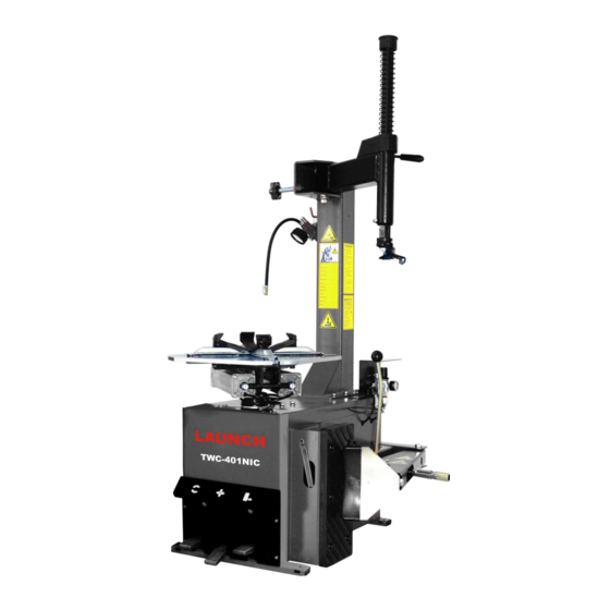
TWC-401NIC
Tire Changer
*Read these instructions
before placing unit in ser-
vice.
**Keep these and other ma-
terials with the unit in a
binder near the machine for
easy reference by supervi-
sors and operators.
***You will need the man-
ual for the information of
the machine, such as safety
warning and precautions,
assembly, operating, main-
tenance and parts list / as-
sembly diagrams.
****Keep
your
invoice
with this manual for future
reference.
Manufacturer
shall not be liable for any
injury to persons on damage
to thins caused by failure to
comply with these regula-
tions and can cancel war-
ranty coverage.
Installation, Operation, Maintenance
Advertisement
Table of Contents

Related Manuals for Launch TWC-401NIC


Summary of Contents for Launch TWC-401NIC
- Page 1 Operation Manual TWC-401NIC Tire Changer *Read these instructions before placing unit in ser- vice. **Keep these and other ma- terials with the unit in a binder near the machine for easy reference by supervi- sors and operators. ***You will need the man-...
-
Page 2: Assembly Instruction
1. Technical Data Model Electric Requirements See the manufacturer’s serial plate Max. Wheel Diameter 39” 42” Max. Wheel Width 13” 14” Outside Clamping—Rim sizes 10” ~ 18” 11” ~ 21” Inside Clamping—Rim sizes 12” ~ 20” 13”~ 23” Max Inflation Pressure 116PSI (8 Bar) Bead Breaker Force 5500Lbs (2500kgs) - Page 3 Bead Breaker Pedal Jaw clamp Pedal Reverse Pedal Turntable Mounting head Hexagonal shaft Swing arm Locking handle 10 Column 11 FRL 12 Shovel 13 Rubber wheel support 14 STL...
- Page 4 (4.1) Optional Upgrade Accessories...
- Page 5 5-4 Workplace Requirements The machine’s workplace requires 1400(width)×1685(depth) with at least 500 mm of clear space from each wall. Place the tire changer on a firm, smooth and unbroken floor. Drill four holes in the floor corresponding to the holes pre-drilled in the base of the machine. Holes should be 80mm deep. Its diameter is 10mm.
-
Page 6: Bead Loosening And Demounting
(6) Operating Instructions This unit must be properly operated and properly main- tained to help avoid accidents that could damage the unit and injure the operator or bystanders. This section of the Operat- ing Instructions manual review basic operations and use of Tires are always installed and removed from the rim’s controls. - Page 7 7. Move the swing arm into position. Pull the locking handle forward to release the slide. Push down on the top of the vertical slide to move the demount head into contact with the rim edge. Push the locking handle back and lock the slide into place (figure 7).
- Page 8 H. The tool clearance may change with machine use and 12. Depress the table top pedal to rotate the wheel. The should be inspected often. Failure to maintain the proper Mounting head will guide the tire bead up and over the edge clearance may result in damage to the wheel rim and/or tire.
- Page 9 (8) Mounting 1. Before any mounting, inspect tire for damage and verify size match between tire and wheel (fig. 14). This information must be read and followed carefully to prevent accidents and injuries during mounting. Attempts to force a bead seat on mismatched tires and wheels can cause the tire to violently explode, causing serious personal injury or death to operator and/or bystanders.
- Page 10 4. Place tire over wheel and move swing arm into position (9) Inflation making sure the valve stem is at the 9 o’clock position in Tire inflation is performed in three steps: BEAD SEAL, front of bead lock. Position tire so that lower bead is above BEAD SEAT, and INFLATION.
- Page 11 T. If tire and wheel are properly lubricated and operator cannot achieve bead seal after three or four attempts, the valve core may be removed from the valve stem to allow more air flow into the tire to assist with bead seal. After bead seal is achieved, remove the clip-on chuck and rein- Use of bead sealing jets without a tire in place can cause stall the valve core.
-
Page 12: Stages Of Inflation On A Conventional Tire And Rim
(11) Stages of Inflation on a Conventional Tire and Rim Review these descriptions and diagrams carefully. Refer to them as necessary during bead sealing, bead seating, and inflation to verify that you are proceeding properly and safely. Bead Sealing Bead sealing is the process of capturing air pressure between the tire and the rim. The tire will usually contain about 1/2 to 2 PSI at initial bead seal.
Need help?
Do you have a question about the TWC-401NIC and is the answer not in the manual?
Questions and answers