Table of Contents
Advertisement
Available languages
Available languages
Quick Links
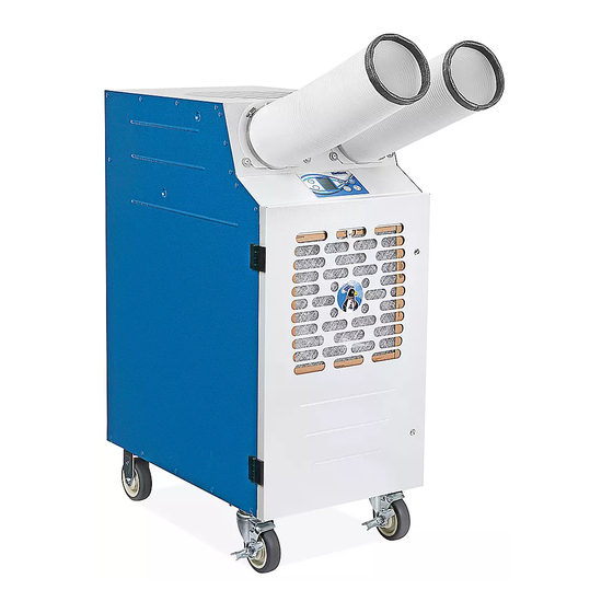
H-8771, H-8772
INDUSTRIAL AIR
CONDITIONER
TOOLS NEEDED
Phillips Screwdriver
Before installing and using the industrial A/C system,
read these instructions carefully for proper usage and
all safeguards. Keep them for future reference.
AIR CHUTE
A/C systems come equipped with air chutes.
1.
Remove air chutes from accessories box. Place
unfinished end of air chute onto collar. Clamp with
supplied clamp using a 5/16 nut driver or a flat
screwdriver. (See Figure 1)
Figure 1
Air Chute
PAGE 1 OF 21
1-800-295-5510
uline.com
Flathead Screwdriver
INSTALLATION
Collar
Clamp
5/16" Wrench
CONDENSATE TANK
The system comes standard
with an internal 3.5-gallon
condensate tank. (See Figure 2)
The internal condensate tank
is equipped with a float switch
that shuts the unit down and
alerts operators with an alarm.
It displays CF (Condensate
Full) when the condensate
tank is full. This prevents
accidental water overflow on
floor. To continue operation, the collection bottle must
be removed, emptied and re-installed. Turning the A/C
unit off will stop the alarm.
1.
Remove the float switch jack by pulling it straight
back. Remove the condensate bottle by pushing
the front of the bottle slightly downward and then
pull the bottle out.
2. Remove the cap threaded onto the bottle by turning
counterclockwise. Empty collected water and
return cap back onto bottle by turning clockwise.
Do not cross thread cap upon installation. Tighten
cap to the point where the angle connector on the
condensate bottle aligns with the nipple extending
out from the drain pan on the A/C unit. Insert bottle
by pushing down slightly to clear extended drain
pan nipple. Ensure drain pan nipple is inside of
angle connector and cap is snug and not cross-
threaded to avoid water leakage.
3. Install the float switch jack by pushing it straight in.
Alarm will sound if pin is not fully inserted. Continue
normal operation.
Para Español, vea páginas 8-14.
Pour le français, consulter les pages 15-21.
Figure 2
Switch Jack
0920 IH-8771
Advertisement
Table of Contents

Related Manuals for U-Line H-8771


Summary of Contents for U-Line H-8771
- Page 1 Para Español, vea páginas 8-14. Pour le français, consulter les pages 15-21. H-8771, H-8772 1-800-295-5510 uline.com INDUSTRIAL AIR CONDITIONER TOOLS NEEDED Phillips Screwdriver Flathead Screwdriver 5/16" Wrench INSTALLATION CONDENSATE TANK Before installing and using the industrial A/C system, Figure 2...
- Page 2 INSTALLATION CONTINUED CEILING DUCT KIT (OPTIONAL) FOR DROP CEILING NOTE: A ladder may be needed for this step. PARTS INCLUDED IN CEILING DUCT KIT Locate area for installation. #2 Phillips 2. Review area above ceiling tile to confirm that it can Exhaust Port Collar Fastener x 6 with Foam Tape x 1...
-
Page 3: Operation
OPERATION POWER CONNECTION CONTROL PANEL Verify the power source, phase and breaker size is The control panel display shows the current operational compatible with A/C serial plate information and the status of the unit. (See Figure 5) electrical circuit is dedicated only for use of the A/C unit. Figure 5 If unsure about power, contact a licensed electrician. -
Page 4: System Operation
OPERATION CONTINUED BUILT-IN SAFEGUARDS 5. Up (+) and Down (–) Arrow Buttons – These raise or lower desired set temperature. When changing TIME DELAY set point, pressing the + or – key, the word SET will appear on the display and the current set point This protects A/C unit from potential damage by flashes ON and OFF. -
Page 5: Maintenance
OPERATION CONTINUED POSITIONING OF UNIT Diminished performance is possible. The high pressure switch is a manual reset. The reset switch is located in Do not place A/C unit in direct sunlight. Position unit so the condenser make-up air inlet on back of system. that the output of the unit can be focused as closely Re-set unit by pressing the HP Reset button. - Page 6 TROUBLESHOOTING CONTINUED OPERATING ISSUE CAUSES RECOMMENDATIONS Unit displays AL and Microprocessor board has detected High pressure is normally caused by audio alarm is sounding high pressure. The high pressure reduced condenser air flow. during start up or while switch is tripped. Check for restriction in ducting.
- Page 7 TROUBLESHOOTING CONTINUED OPERATING ISSUE CAUSES RECOMMENDATIONS Evaporator coil is Low or restricted air flow Direct supply return air to area of highest freezing. heat load. Check for blocked air flow from the supply air. Replace air filters. Undersized capacity, unit constantly Adjust set point to allow the unit to cycle.
-
Page 8: Instalación
H-8771, H-8772 800-295-5510 uline.mx AIRE ACONDICIONADO INDUSTRIAL HERRAMIENTAS NECESARIAS Desarmador de Cruz Desarmador Plano Llave de 5/16" INSTALACIÓN TANQUE DE Antes de instalar y usar el sistema de aire Diagrama 2 acondicionado industrial, lea con cuidado estas CONDENSADO instrucciones para su uso y medidas de seguridad adecuados. - Page 9 CONTINUACIÓN DE INSTALACIÓN KIT DEL CONDUCTO DE TECHO (OPCIONAL) PARA TECHO FALSO NOTA: Es posible que se necesite una escalera para este paso. PARTES INCLUIDAS EN EL KIT DE CONDUCTO DE TECHO Ubica el área de instalación. 1 Collar del Puerto 6 Sujetadores 2.
-
Page 10: Conexión Eléctrica
FUNCIONAMIENTO CONEXIÓN ELÉCTRICA PANEL DE CONTROL Verifique que la fuente de energía, fase y el tamaño del La pantalla del panel de control muestra el estado de interruptor automático sea compatible con la información de la operación actual de la unidad. (Vea Diagrama 5) placa de serie del aire condicionado y que el circuito eléctrico esté... - Page 11 CONTINUACIÓN DE FUNCIONAMIENTO MEDIDAS DE SEGURIDAD INTEGRADAS Botones de las Flechas Arriba (+) y Abajo (–) – Estos suben o bajan la temperatura ajustada deseada. Al cambiar el punto configurado y presionar la tecla + o – , la palabra TIEMPO DE RETARDO SET aparecerá...
-
Page 12: Mantenimiento
CONTINUACIÓN DE FUNCIONAMIENTO POSICIONAR LA UNIDAD Un rendimiento reducido es posible. El interruptor de alta presión se restaura de manera manual. El interruptor de No coloque la unidad de aire acondicionado en luz solar reinicio está ubicado en la entrada de aire de reposición directa. - Page 13 CONTINUACIÓN DE SOLUCIÓN DE PROBLEMAS PROBLEMA DE CAUSAS RECOMENDACIONES FUNCIONAMIENTO La unidad muestra AL La tarjeta del microprocesador detectó Alta presión normalmente está ocasionada y la alarma de audio alta presión. El interruptor de alta por la circulación de aire del condensador está...
- Page 14 CONTINUACIÓN DE SOLUCIÓN DE PROBLEMAS PROBLEMA DE CAUSAS RECOMENDACIONES FUNCIONAMIENTO La bobina del Circulación de aire baja o restringida Dirige el suministro de aire de regreso al área evaporador se está de carga de calor más alto. congelando. Revise por obstrucción en la circulación de aire del suministro de aire.
-
Page 15: Installation
H-8771, H-8772 1-800-295-5510 uline.ca CLIMATISEUR INDUSTRIEL OUTILS REQUIS Tournevis cruciforme Tournevis à tête plate Clé de 5/16 po INSTALLATION RÉSERVOIR DE Avant d'installer et d'utiliser le système de climatisation Figure 2 industriel, lisez minutieusement ces instructions pour CONDENSATS prendre connaissance des procédures d'utilisation adaptées et de toutes les mesures de sécurité. - Page 16 INSTALLATION SUITE ENSEMBLE DE CONDUITES POUR POUR LES FAUX PLAFONDS PLAFOND (OPTIONNEL) REMARQUE : Il se peut que vous ayez besoin d'une échelle pour cette étape. PIÈCES INCLUSES DANS L'ENSEMBLE Repérez l'emplacement pour l'installation. DE CONDUITES POUR PLAFOND 2. Inspectez l'espace situé au-dessus de la dalle de Collier de l'orifice Pièce de fixation plafond pour vous assurer qu'il est adapté...
-
Page 17: Prise D'alimentation
FONCTIONNEMENT PRISE D'ALIMENTATION PANNEAU DE COMMANDE Vérifiez que la source d'alimentation, la phase et la taille du L'écran du panneau de commande affiche l'état disjoncteur sont compatibles avec les informations figurant opérationnel de l'appareil. (Voir Figure 5) sur la plaque de série du climatiseur et que le circuit électrique est entièrement dédié... -
Page 18: Fonctionnement Du Système
FONCTIONNEMENT SUITE DISPOSITIFS DE SÉCURITÉ INTÉGRÉS Boutons de flèches vers le haut (+) et vers le bas (–) – Ces boutons permettent d'augmenter et d'abaisser la température programmée. Lorsque vous appuyez sur TEMPORISATION la touche + ou – pour modifier le point de consigne, le mot SET apparaît sur l'écran et le point de consigne Ce dispositif permet de protéger le climatiseur de dommages actuellement sélectionné... -
Page 19: Dépannage
FONCTIONNEMENT SUITE POSITIONNEMENT DE L'APPAREIL Ceci peut entraîner une diminution du rendement. Le commutateur haute pression doit être réinitialisé manuellement. Le commutateur Placez le climatiseur à l'abri de la lumière directe du soleil. de réinitialisation est situé dans l'orifice d'admission d'air d'appoint Positionnez l'appareil de manière à... - Page 20 DÉPANNAGE SUITE PROBLÈME CAUSES RECOMMANDATIONS L'appareil affiche AL La carte de microprocesseur a Une pression élevée est normalement causée et l'alarme sonore se détecté une pression élevée. Le par une circulation de l'air réduite à l'intérieur du déclenche durant commutateur haute pression s'est condensateur.
- Page 21 DÉPANNAGE SUITE PROBLÈME CAUSES RECOMMANDATIONS Le serpentin d'évaporateur Circulation de l'air faible ou restreinte. Dirigez l'air fourni/de retour en direction de la est en train de geler. charge calorifique la plus élevée. Vérifiez que la circulation de l'air founi n'est pas bloquée.
Need help?
Do you have a question about the H-8771 and is the answer not in the manual?
Questions and answers