Table of Contents
Advertisement
Advertisement
Table of Contents

Related Manuals for Barox LT-802GBTME


Summary of Contents for Barox LT-802GBTME
- Page 1 Kommunikation LT-802GBTME User Manual Version 1.0...
- Page 2 Barox Kommunikation may make improvements and/or changes to the product and/or specifications of the product described in this manual, without prior notice. Barox Kommunikation will not be liable for any technical inaccuracies or typographical errors found in this guide. Changes are periodically made to the information contained herein and will be incorporated into later versions of the manual.
- Page 3 Kommunikation FCC Notice This equipment has been tested and found to comply with the limits for a Class-A digital device, pursuant to Part 15 of the FCC rules. These limits are designed to provide reasonable protection against harmful interference in a residential installation. This equipment generates, uses, and can radiate radio frequency energy.
-
Page 4: Table Of Contents
Kommunikation Contents Overview ..................................1 Software Features ..............................1 Hardware Features ..............................2 Package Contents ..............................3 Safety Precaution ..............................3 Hardware Description ..............................4 Physical Dimensions ............................... 4 Front Panel ................................5 Top View ................................. 5 LED Indicators ................................. 6 Ethernet Ports ................................. -
Page 5: Overview
Kommunikation Overview This series is rated IP30 and installation by DIN Rail. Each unit of this industrial gigabit managed Ethernet switch series has 8 10/100/1000Tx Gigabit Ethernet ports and 2 dual-rate (100/1000) SFP slots, suitable for applications that require high bandwidth and long distance communication. -
Page 6: Hardware Features
Kommunikation Event notification by Email: Cold/Warm Start, Power Failure, Authentication, SNMP trap and Fault Alarm Relay Output Software Upgrade TFTP, Web GUI, CLI USB Port Configuration Backup Hardware Features Interface & Performance All Copper ports support auto MDI/MDI-X function ... -
Page 7: Package Contents
Kommunikation Package Contents 1 – LT-802GBTME: 10-port industrial gigabit managed Ethernet switch, with 8*10/100/1000Tx Gigabit Ethernet and 2*100/1000 SFP Slots 1 - User manual CD 2 - Wall mounting brackets and screws 1 - RJ45 to DB9 Serial Console cable ... -
Page 8: Hardware Description
Kommunikation Hardware Description Physical Dimensions Figure 2.1, below, shows the physical dimensions of LT-802GBTMEseries: 10-port industrial gigabit managed Ethernet switch, with 8*10/100/1000Tx Gigabit Ethernet and 2*100/1000 SFP Slots. (W x H x D) is 54mm x 142mm x 99mm... -
Page 9: Front Panel
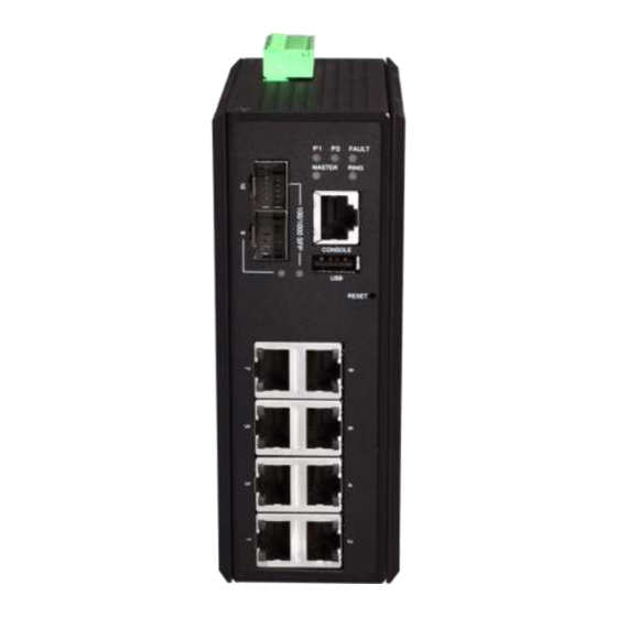
Kommunikation Front Panel The front panel of the LT-802GBTMEseries industrial gigabit managed Ethernet switch is shown below in Figure 2.2. Figure 2.2: The Front Panel of LT-802GBTMESeries Top View Figure 2.3, below, shows the top panel of the LT-802GBTMEseries switch that is equipped with one 6- pin removal terminal block connector for dual DC power inputs (12-48VDC). -
Page 10: Led Indicators
Kommunikation LED Indicators There are LED light indicators located on the front panel of the industrial Ethernet switch that display the power status and network status. Each LED indicator has a different color and has its own specific meaning, see below in Table 2.1. -
Page 11: Ethernet Ports
Kommunikation Ethernet Ports RJ-45 Ports(Auto MDI/MDIX) The RJ-45 ports are auto-sensing for 10Base-T, 100Base-TX or 1000Base-T devices connections. Auto MDI/MDIX means that the switch can connect to another switch or workstation without changing the straight-through or crossover cabling. See the figures as below for straight-through and crossover cabling schematics. -
Page 12: Cabling
Kommunikation The following figures show the 10,100, and 1000 Ethernet RJ-45 pin outs. Figure 2.6: RJ45 Ethernet Port Pin Outs Figure 2.7: Straight-Through Cable Schematic Figure 2.8: Crossover Cable Schematic Cabling Use the four twisted-pair, category 5e, or the above cabling for RJ-45 port connections. The cable between the switch and the link partner (switch, hub, workstation, etc.) must be less than 100 meters... - Page 13 Kommunikation To connect the transceiver and LC cable, please follow below steps: Insert the SFP transceiver module into the SFP slot as shown below in Figure 2.9. Notice that Step 1. the triangle mark is at the bottom of the SFP slot. Figure 2.10 shows SFP transceiver module was inserted.
- Page 14 Kommunikation To remove the LC connector from the transceiver, please follow the steps shown below: Press the upper side of the LC connector from the transceiver and pull it out to release as Step 1. shown below in Figure 2.12 Figure 2.12: Remove LC Connector...
-
Page 15: Wiring The Power Inputs
Kommunikation Wiring the Power Inputs Please follow the below steps to insert the power wire. Insert the positive and negative wires into the PWR1 (V1+, V1-) and PWR2 (V2+, V2-) contacts Step 1. on the terminal block connector as shown below in Figure 2.14. -
Page 16: Wiring The Fault Alarm Contact
Kommunikation Wiring the Fault Alarm Contact The fault alarm contact is in the middle of the terminal block connector as the picture shows below in Figure 2.16. By inserting the wires, it will detect the fault status including power failure or port link failure (managed industrial switch only) and form a normally open circuit. -
Page 17: Mounting Installation
Kommunikation Mounting Installation DIN-Rail Mounting The DIN-Rail is pre-installed on the industrial Ethernet switch from the factory. If the DIN-Rail is not on the industrial Ethernet switch, please see Figure 3.1 to learn how to install the DIN-Rail on the switch. - Page 18 Kommunikation Figure 3.3: Stable the Switch on DIN-Rail Check if the bracket is mounted tightly on the rail. Step 5. To remove the industrial Ethernet switch from the rail, do the opposite from the above steps. Step 6.
-
Page 19: Wall Mounting
Kommunikation Wall Mounting Follow the steps below to mount the industrial Ethernet switch using the wall mounting bracket as shown below in Figure 3.4. Remove the DIN-Rail bracket from the industrial Ethernet switch by loosening the screws. Step 1. -
Page 20: Hardware Installation
Kommunikation Hardware Installation Installation Steps This section will explain how to install LT-802GBTMEseries: 10-port industrial gigabit managed Ethernet switch, with 8*10/100/1000Tx Gigabit Ethernet and 2*100/1000 SFP Slots Installation Steps Unpack the industrial Ethernet switch from the original packing box. -
Page 21: Trouble Shooting
Check for loose power connections, power losses or surges at the power outlet. ◆ Please contact barox Kommunikation for technical support service, if the problem still cannot be resolved. ● If the industrial switch LED indicators are normal and the connected cables are correct but the... -
Page 22: Technical Specification
Kommunikation Technical Specification Table 7.1 has the technical specifications for LT-802GBTMEseries: 10-port industrial gigabit managed Ethernet switch, with 8*10/100/1000Tx Gigabit Ethernet and 2*100/1000 SFP Slots IEEE 802.3 10BaseT Ethernet IEEE 802.3u 100BaseTX Fast Ethernet IEEE 802.3ab 1000BaseT IEEE 802.3z 1000Base-X IEEE 802.3x flow control... - Page 23 Kommunikation EIA/TIA-568 100-ohm (100m) 100BaseTX: 2-pair UTP/STP Cat. 5 cable EIA/TIA-568 100-ohm (100m) 1000BaseTX: UTP/STP Cat. 5/5E cable EIA/TIA-568 100-ohm (100m) Over Current Protection Present(Slow-Blown Fuse) Power Reverse Polarity Present Protection CPU Watch Dog Present Redundant power DC 12-48V with connective...
Need help?
Do you have a question about the LT-802GBTME and is the answer not in the manual?
Questions and answers