Table of Contents
Advertisement
Quick Links
Advertisement
Table of Contents

Related Manuals for Barox LT-PIGE-804GBTME Series


Summary of Contents for Barox LT-PIGE-804GBTME Series
- Page 1 LT-PIGE-804GBTME User Manual Version 1.0...
- Page 2 Barox Kommunikation may make improvements and/or changes to the product and/or specifications of the product described in this manual, without prior notice. Barox Kommunikation will not be liable for any technical inaccuracies or typographical errors found in this guide. Changes are periodically made to the information contained herein and will be incorporated into later versions of the manual.
- Page 3 FCC Notice This equipment has been tested and found to comply with the limits for a Class-A digital device, pursuant to Part 15 of the FCC rules. These limits are designed to provide reasonable protection against harmful interference in a residential installation. This equipment generates, uses, and can radiate radio frequency energy.
-
Page 4: Table Of Contents
Contents Overview ..................................1 Software Features ..............................1 Hardware Features ..............................2 Package Contents ..............................3 Safety Precaution ..............................3 Hardware Description ..............................4 Physical Dimensions ............................... 4 Front Panel ................................5 Top View ................................. 5 LED Indicators ................................. 6 Ethernet Ports ................................. -
Page 5: Overview
Overview This series is rated IP30 and installation by DIN Rail. Each unit of this industrial gigabit managed Ethernet switch series has 8 IEEE 802.3at compliant ports (30W/port) and 4 dual-rate (100/1000) SFP slots, suitable for applications that require high bandwidth and long distance communication. In order to prevent unregulated voltage, this series provides high EFT and ESD protection. -
Page 6: Hardware Features
PoE ports weekly power scheduling Port Configuration Port Status, Statistics, Monitoring, Mirroring, Security, and Rate Limiting, SFP DDM Event Handling Event notification by Email: Cold/Warm Start, Power Failure, Authentication, SNMP trap and Fault Alarm Relay Output Software Upgrade ... -
Page 7: Package Contents
Package Contents 1 - LT-PIGE-804GBTME: 12-port industrial PoE+ gigabit managed Ethernet switch, with 8*10/100/1000Tx (PSE 30W/Port) and 4*100/1000 SFP Slots 1 - User manual CD 2 - Wall mounting brackets and screws 1 - RJ45 to DB9 Serial Console cable ... -
Page 8: Hardware Description
Hardware Description Physical Dimensions Figure 2.1, below, shows the physical dimensions of LT-PIGE-804GBTME series: 12-port industrial PoE+ gigabit managed Ethernet switch, with 8*10/100/1000Tx (PSE 30W/Port) and 4*100/1000 SFP Slots. (W x H x D) is 46mm x 142mm x 99mm... -
Page 9: Front Panel
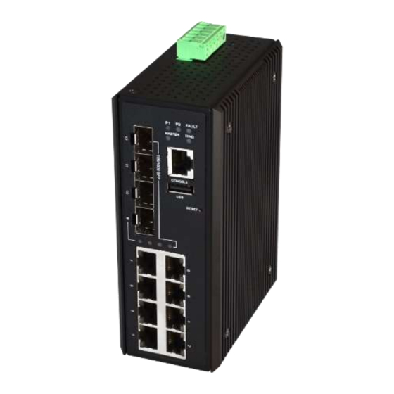
Figure 2.2: The Front Panel of LT-PIGE-804GBTME Series Top View Figure 2.3, below, shows the top panel of the LT-PIGE-804GBTME series switch that is equipped with one 6-pin removal terminal block connector for dual DC power inputs (48-55VDC). Figure 2.3: Top Panel View of LT-PIGE-804GBTME Series... -
Page 10: Led Indicators
LAN Port 1-8 Flashing Networking is active (Left LED) Not connected to network Green The port is supplying power to the powered-device LAN Port 1-8 (Right LED) No powered-device attached or power supplying fails Table 2.1: LED Indictors for LT-PIGE-804GBTME Series... -
Page 11: Ethernet Ports
Ethernet Ports RJ-45 Ports(Auto MDI/MDIX) The RJ-45 ports are auto-sensing for 10Base-T, 100Base-TX or 1000Base-T devices connections. Auto MDI/MDIX means that the switch can connect to another switch or workstation without changing the straight-through or crossover cabling. See the figures as below for straight-through and crossover cabling schematics. -
Page 12: Cabling
The following figures show the 10,100, and 1000 Ethernet RJ-45 pin outs. Figure 2.6: RJ45 Ethernet Port Pin Outs Figure 2.7: Straight-Through Cable Schematic Figure 2.8: Crossover Cable Schematic Cabling Use the four twisted-pair, category 5e, or the above cabling for RJ-45 port connections. The cable between the switch and the link partner (switch, hub, workstation, etc.) must be less than 100 meters (328 ft.) long. - Page 13 To connect the transceiver and LC cable, please follow below steps: Insert the SFP transceiver module into the SFP slot as shown below in Figure 2.9. Notice that Step 1. the triangle mark is at the bottom of the SFP slot. Figure 2.10 shows SFP transceiver module was inserted.
- Page 14 To remove the LC connector from the transceiver, please follow the steps shown below: Press the upper side of the LC connector from the transceiver and pull it out to release as Step 1. shown below in Figure 2.12 Figure 2.12: Remove LC Connector Push down the metal clasp and pull the transceiver out by the plastic part as shown below in Step 2.
-
Page 15: Wiring The Power Inputs
Wiring the Power Inputs Please follow the below steps to insert the power wire. Insert the positive and negative wires into the PWR1 (V1+, V1-) and PWR2 (V2+, V2-) contacts Step 1. on the terminal block connector as shown below in Figure 2.14. Figure 2.14: Power Terminal Block Tighten the wire-clamp screws to prevent the wires from loosening, as shown below in Figure Step 2. -
Page 16: Wiring The Fault Alarm Contact
Wiring the Fault Alarm Contact The fault alarm contact is in the middle of the terminal block connector as the picture shows below in Figure 2.16. By inserting the wires, it will detect the fault status including power failure or port link failure (managed industrial switch only) and form a normally open circuit. -
Page 17: Mounting Installation
Mounting Installation DIN-Rail Mounting The DIN-Rail is pre-installed on the industrial Ethernet switch from the factory. If the DIN-Rail is not on the industrial Ethernet switch, please see Figure 3.1 to learn how to install the DIN-Rail on the switch. Figure 3.1: The Rear Side of the Switch and DIN-Rail Bracket Follow the steps below to learn how to hang the industrial Ethernet switch. - Page 18 Figure 3.2: Insert the Switch on the DIN-Rail Lightly pull down the bracket on to the rail as shown below in Figure 3.3. Step 4. Figure 3.3: Stable the Switch on DIN-Rail Check if the bracket is mounted tightly on the rail. Step 5.
-
Page 19: Wall Mounting
Wall Mounting Follow the steps below to mount the industrial Ethernet switch using the wall mounting bracket as shown below in Figure 3.4. Remove the DIN-Rail bracket from the industrial Ethernet switch by loosening the screws. Step 1. Place the wall mounting brackets on the top and bottom of the industrial Ethernet switch. Step 2. -
Page 20: Hardware Installation
Hardware Installation Installation Steps This section will explain how to install LT-PIGE-804GBTME series: 12-port industrial PoE+ gigabit managed Ethernet switch, with 8*10/100/1000Tx (PSE 30W/Port) and 4*100/1000 SFP Slots Installation Steps Unpack the industrial Ethernet switch from the original packing box. -
Page 21: Trouble Shooting
Trouble Shooting ● Verify you have the right power cord or adapter. Never use a power supply or adapter with a non- compliant DC output voltage or it will burn the equipment. ● Select the proper UTP or STP cable in order to construct the network. Use an unshielded twisted- pair (UTP) or shield twisted-pair (STP) cable for RJ-45 connections: 100Ω... -
Page 22: Technical Specification
Technical Specification Table 7.1 has the technical specifications for LT-PIGE-804GBTME series: 12-port industrial PoE+ gigabit managed Ethernet switch, with 8*10/100/1000Tx (PSE 30W/Port) and 4*100/1000 SFP Slots IEEE 802.3 10BaseT Ethernet IEEE 802.3u 100BaseTX Fast Ethernet IEEE 802.3ab 1000BaseT IEEE 802.3z 1000Base-X IEEE 802.3af/at Power over Ethernet... - Page 23 CE EN55022 Class A ; EN55024 EMI/EMS CE EN61000-4-2/3/4/5/6/8 CE EN61000-6-2, Emission for industrial environment CE EN61000-6-4, Immunity for Industrial environment IEC60068-2-32 (Free fall) Stability Testing IEC60068-2-27 (Shock) IEC60068-2-6 (Vibration) Safety UL 508 (Pending) Table 7.1: LT-PIGE-804GBTME Series Technical Specification...
Need help?
Do you have a question about the LT-PIGE-804GBTME Series and is the answer not in the manual?
Questions and answers