Table of Contents
Advertisement
Quick Links
D-040L 2".IOM.ENG02
Installation, Operation & Maintenance
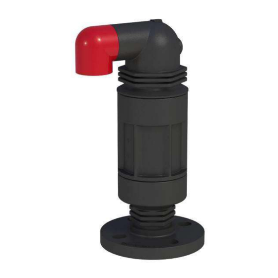
COMBINATION AIR VALVE
MODEL D-040L 2"
The following is a step by step narrated description of the A.R.I. 2" D-040L Combination Air Valve
installation, operation and maintenance processes.
The D-040L series Combination Air Valve has the features of both an air release valve and an air & vacuum
valve. The air release component is designed to automatically release small pockets of air to the
atmosphere as they accumulate along a pipeline or piping system when it is full and operating under
pressure. Please consult A.R.I. for the pressure and temperature framework of this model specifications
table and for other products designed for hazardous liquids systems.
Advertisement
Table of Contents

Related Manuals for ARI D-040L


Summary of Contents for ARI D-040L
- Page 1 The D-040L series Combination Air Valve has the features of both an air release valve and an air & vacuum valve. The air release component is designed to automatically release small pockets of air to the atmosphere as they accumulate along a pipeline or piping system when it is full and operating under pressure.
-
Page 2: Table Of Contents
IOM D-040L 2” TABLE OF CONTENTS 1. SAFETY INSTRUCTIONS ............................. 3 2. INSTALLATION ..............................6 3. OPERATION ..............................9 4. TROUBLE SHOOTING ............................9 5. PERIODIC MAINTENANCE ..........................10 5.1. Preparation ............................. 10 5.2. First Stage Maintenance ......................... 10 5.3. Second Stage Maintenance ........................13 6. -
Page 3: Safety Instructions
IOM D-040L 2” 1. SAFETY INSTRUCTIONS General 1. A.R.I. products always operate as components in a larger system. It is essential for the system designers, installers, operators and maintenance personnel to comply with all the relevant safety standards. 2. Installation, operation or maintenance of the product should be done only by qualified workers, technicians... - Page 4 IOM D-040L 2” Installation 1. Install the product according to the detailed Installation Instructions provided with it by A.R.I. and according to the description given in this manual. 2. The user should install a manual Isolation Valve under the product's inlet port.
- Page 5 IOM D-040L 2” Before returning to regular operation 1. Re-assemble any protection covers or protection mechanisms removed during service or maintenance operations. 2. Make sure that all the tools, ladders, lifting devices, etc. used during the maintenance procedures are taken away from the product area and stored.
-
Page 6: Installation
IOM D-040L 2” 2. INSTALLATION Important: Before performing any work on the air valve make sure that all workers on site are familiar with the safety instructions and the relevant local and general safety instructions and work regulations. 2.1. Installation Recommendations Single Air Valve on an Isolating Valve at 45°... - Page 7 IOM D-040L 2” 2.2. Conventions and Measurements This paragraph presents and explains the terms and measurements used for the Installation process. D = Diameter of pipeline Isolation Valve d = diameter of riser H = Height of riser on the pipeline (Measured from crown of pipeline) •...
- Page 8 IOM D-040L 2” 2.3. Installation Instructions 1. Flush the system before installing the air valve to avoid any debris or sharp objects getting into the air valve. 2. Carefully remove the air valve from the shipping package. Unload all air valves carefully to a sturdy level surface taking care not to drop them.
-
Page 9: Operation
3. OPERATION The D-040L series Combination Air Valve has the features of both an air release valve and an air & vacuum valve. The air release component is designed to automatically release small pockets of air to the atmosphere as they accumulate along a pipeline or piping system when it is full and operating under pressure. -
Page 10: Periodic Maintenance
IOM D-040L 2” 5. PERIODIC MAINTENANCE Please note that the periodic maintenance of the air valve is an integral part of the proper pipeline maintenance regime; it should be maintained at least once a year in accordance with the quality and composition of the fluid in the system. - Page 11 IOM D-040L 2” 5.2.2 Removal of the Valve’s Body • Slowly turn the Body (1) counterclockwise, and remove it [2]. • Remove the Discharge Outlet Elbow [3], [4] (snap-on or thread).
- Page 12 IOM D-040L 2” 5.2.3. Cleaning of the Air Valve • Thoroughly wash and clean the air valve components under clean running water to remove all grime; Pay special attention to the internal parts. • Thoroughly clean the O-ring (replace it if needed [1]. Make sure that the O-ring is correctly seated in its designated groove [2].
-
Page 13: Second Stage Maintenance
IOM D-040L 2” 5.3. Second Stage Maintenance Perform if the first stage doesn't solve the leak, if one of the seals or inner parts need replacement or for periodic maintenance to thoroughly clean the valve. 5.3.1. Releasing Pressure • Shut the isolating valve located on the riser under the air valve •... - Page 14 IOM D-040L 2” 5.3.3. Disassembly of the Float • Hold the Operating Valve Body, turn it to the side and use a flat-tip screwdriver [1] to remove the Clamping Stem [2] and the Float (together with the Rolling Seal [3]).
- Page 15 IOM D-040L 2” • Unscrew and remove the Body Extension from the Base [6]. Thoroughly clean these two parts [7] • Thoroughly clean the base O-ring (replace it if needed [8]. Make sure that the O-ring is correctly seated in its designated groove [9].
- Page 16 IOM D-040L 2” 5.3.3. Cleaning and inspecting the float components • Thoroughly wash and clean the air valve components under clean running water to remove all grime; Pay special attention to the internal parts. • Visually check the condition of the Rolling Seal [1] & [2]. If any cracks or tears are found remove it from the Float and replace it.
- Page 17 IOM D-040L 2” Pay attention to the correct position and direction and insert the tail end of the Rolling Seal Assembly into the groove on the Float [5]. Gently pull the Rolling Seal Assembly until it is partially inserted into the Float grove. Use the 4.5mm Roll Pin Punch to push the Rolling Seal Assembly to the middle of the Float [6] and align the middle of the Rolling Seal Assembly tail with the midline of the Float [7].
- Page 18 IOM D-040L 2” 5.3.4. Reassembling the Operating Valve Dip the head end of the Rolling Seal into the liquid soap solution [1] Reassemble the Operating Valve by inserting the loose end of the Rolling Seal into its designated groove in the Body,...
- Page 19 IOM D-040L 2” Insert the Float halfway into the Body [1], insert the Clamping Stem into the Rolling Seal groove of the Body; make sure that it is inserted in the correct direction [2]. Push the Float and the Clamping Stem together downwards into the Body until they are locked [3].
-
Page 20: Assembly Bom Table And Drawing
IOM D-040L 2” 6. ASSEMBLY BOM TABLE AND DRAWING Body Discharge Outlet Elbow Clamping Stem Float Rolling Seal O-ring Body Extension Base O-ring Flange... -
Page 21: Limited Warranty
IOM D-040L 2” 7. A.R.I. LIMITED WARRANTY A.R.I. Standard International Warranty A.R.I. manufactured products are guaranteed to be free from defect in material and/or workmanship and to perform as advertised when properly installed, used and maintained in accordance with current instructions, written or verbal.
Need help?
Do you have a question about the D-040L and is the answer not in the manual?
Questions and answers