Table of Contents
Advertisement
Quick Links
Advertisement
Table of Contents

Related Manuals for Lenovo 10TV004GIX


Summary of Contents for Lenovo 10TV004GIX
- Page 1 Questo manuale d’istruzione è fornito da trovaprezzi.it. Scopri tutte le offerte per Lenovo V530-15ICB 10TV004GIX o cerca il tuo prodotto tra le migliori offerte di PC Desktop e Workstation V530-15ICB User Guide and Hardware Maintenance Manual Energy Star Machine Types: 10TV, 10TW, 10XS, and 10XT...
- Page 2 Important Product Information Guide and Appendix A “Notices” on page 57. First Edition (May 2018) © Copyright Lenovo 2018. LIMITED AND RESTRICTED RIGHTS NOTICE: If data or software is delivered pursuant to a General Services Administration “GSA” contract, use, reproduction, or disclosure is subject to restrictions set forth in Contract No. GS-...
-
Page 3: Table Of Contents
....Appendix B. Trademarks ..59 Replacing the storage drive ..© Copyright Lenovo 2018... - Page 4 V530-15ICB User Guide and Hardware Maintenance Manual...
-
Page 5: Chapter 1. Overview
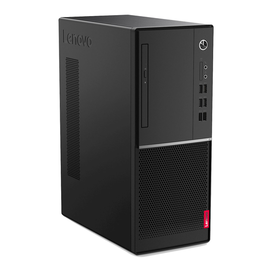
USB 3.1 Gen 2 connectors (2) Storage drive activity indicator Optical drive eject/close button Used to eject the tray of the optical drive. After you insert a disc into the tray, press the eject/close button to close the tray. © Copyright Lenovo 2018... - Page 6 Optical drive activity indicator This indicator is on when the optical drive is in use. Internal speaker Used to listen to the sounds from your computer without using a headset or headphones. Card reader slot Used to read data from a supported memory card. Power indicator This indicator is on when the computer is on.
-
Page 7: Rear View
Rear view Note: Your computer model might look slightly different from the illustration. Figure 2. Rear view Microphone connector VGA-out connector ® DisplayPort 1.2 out connector HDMI 1.4 out connector USB 2.0 connectors (4) Audio line-out connector Audio line-in connector Serial connector Ethernet connector Serial connector (optional) - Page 8 DisplayPort 1.2 out connector Used to send audio and video signals from the computer to another audio or video device, such as a high- performance monitor. HDMI 1.4 out connector Used to send audio and video signals from the computer to another audio or video device, such as a high- performance monitor.
-
Page 9: System Board
Used to connect the power cord to your computer for power supply. System board Note: See “Front view” and “Rear view” for additional component descriptions. Figure 3. System board 4-pin power connector Microprocessor fan connector Buzzer Auxiliary fan connector 2 Memory slot (DIMM2) Memory slot (DIMM4) Power button board connector... -
Page 10: Machine Type And Model Label
Machine type and model label The machine type and model label identifies the computer. When you contact Lenovo for help, the machine type and model information helps support technicians to identify the computer and provide faster service. The machine type and model label is attached on the computer as shown. -
Page 11: Chapter 2. Specifications
• USB connector Expansion • Card reader (optional) • Memory slot • M.2 solid-state drive slot • Optical drive • PCI Express x1 card slot • PCI Express x16 graphics card slot • Storage drive bay © Copyright Lenovo 2018... - Page 12 Network features • Ethernet LAN • Wireless LAN (optional) • Bluetooth (optional) Physical dimensions • Width: 145.0 mm (5.7 inches) • Height: 366.0 mm (14.4 inches) • Depth: 276.0 mm (10.9 inches) Weight (without the package) Maximum configuration as shipped: 6.2 kg (13.7 lb) V530-15ICB User Guide and Hardware Maintenance Manual...
-
Page 13: Chapter 3. Computer Locks
Locking the computer cover helps prevent unauthorized access to the inside of your computer. Your computer features a padlock loop so that the computer cover cannot be removed when a padlock is installed. Figure 5. Locking the computer cover © Copyright Lenovo 2018... -
Page 14: Attaching A Kensington-Style Cable Lock
The cable lock also locks the buttons used to open the computer cover. This is the same type of lock used with many notebook computers. You can order such a cable lock directly from Lenovo by searching for Kensington at: http://www.lenovo.com/support Figure 6. -
Page 15: Chapter 4. Replacing Hardware
• When installing or replacing an option, use the appropriate instructions explained in this manual along with the instructions that come with the option. • In most areas of the world, Lenovo requires the return of defective CRUs. Information about this will come with the CRU or will come a few days after the CRU arrives. -
Page 16: Locating Frus (Including Crus)
• Self-service CRUs: • Optional-service CRUs: • Some of the following components are optional. • To replace a component that is not in the list below, contact a Lenovo service technician. For a list of Lenovo Support phone numbers, go to: http://www.lenovo.com/support/phone... - Page 17 Figure 7. Locating FRUs (including CRUs) Heat sink and fan assembly Computer cover Rear fan Wi-Fi card Wi-Fi card shield Coin-cell battery Microprocessor Memory module System board M.2 solid-state drive M.2 solid-state drive bracket Power button board Optical drive cable Card reader Internal speaker Wi-Fi antennas (2)
-
Page 18: Removing The Computer Cover
Optical drive bracket Optical drive Front bezel Card reader slot cover Keyboard Mouse Power cord Storage drive cable Storage converter Primary or secondary storage drive (a 2.5-inch or 3.5- inch storage drive) Front fan Power supply assembly Chassis PCI Express card Removing the computer cover Attention: Do not open your computer or attempt any repairs before reading the Important Product Information Guide. -
Page 19: Replacing The Front Bezel
Replacing the front bezel Attention: Do not open your computer or attempt any repairs before reading the Important Product Information Guide. 1. Remove the computer cover. See “Removing the computer cover” on page 14. 2. Replace the front bezel. Figure 9. Removing the front bezel Figure 10. -
Page 20: Replacing The Optical Drive
Replacing the optical drive Attention: Do not open your computer or attempt any repairs before reading the Important Product Information Guide. 1. Remove the computer cover. See “Removing the computer cover” on page 14. 2. Remove the front bezel. See “Replacing the front bezel” on page 15. 3. -
Page 21: Replacing The Optical Drive Bracket
6. Reinstall the removed parts. To complete the replacement, see “Completing the parts replacement” on page 55. Replacing the optical drive bracket Attention: Do not open your computer or attempt any repairs before reading the Important Product Information Guide. 1. Remove the computer cover. See “Removing the computer cover” on page 14. 2. -
Page 22: Pivoting The Drive Bay Assembly Upward And Downward
5. Reinstall the removed parts. To complete the replacement, see “Completing the parts replacement” on page 55. Pivoting the drive bay assembly upward and downward Attention: Do not open your computer or attempt any repairs before reading the Important Product Information Guide. -
Page 23: Replacing The Storage Drive
4. Reinstall the removed parts. To complete the replacement, see “Completing the parts replacement” on page 55. Replacing the storage drive Attention: Do not open your computer or attempt any repairs before reading the Important Product Information Guide. Replacing the 3.5-inch storage drive 1. - Page 24 Figure 18. Installing the 3.5-inch primary storage drive • 3.5-inch secondary storage drive Figure 19. Removing the 3.5-inch secondary storage drive V530-15ICB User Guide and Hardware Maintenance Manual...
- Page 25 Figure 20. Installing the 3.5-inch secondary storage drive 6. Connect the signal cable and the power cable to the new 3.5-inch storage drive. 7. Reinstall the removed parts. To complete the replacement, see “Completing the parts replacement” on page 55. Replacing the 2.5-inch storage drive 1.
-
Page 26: Replacing A Memory Module
Figure 22. Installing the 2.5-inch storage drive into the storage converter 3. Reinstall the storage converter with the 2.5-inch storage drive. See “Replacing the 3.5-inch storage drive”. Replacing a memory module Attention: Do not open your computer or attempt any repairs before reading the Important Product Information Guide. - Page 27 3. Pivot the drive bay assembly upward. See “Pivoting the drive bay assembly upward and downward” on page 18. 4. Replace a memory module. Figure 23. Disengaging the latches Figure 24. Removing a memory module Figure 25. Installing a memory module Chapter 4 Replacing hardware...
-
Page 28: Replacing The Heat Sink And Fan Assembly
Figure 26. Securing a memory module with the latches 5. Reinstall the removed parts. To complete the replacement, see “Completing the parts replacement” on page 55. Replacing the heat sink and fan assembly Attention: Do not open your computer or attempt any repairs before reading the Important Product Information Guide. -
Page 29: Replacing The Coin-Cell Battery
Figure 27. Removing the heat sink and fan assembly Figure 28. Installing the heat sink and fan assembly 6. Connect the new microprocessor fan cable to the system board. 7. Reinstall the removed parts. To complete the replacement, see “Completing the parts replacement” on page 55. - Page 30 Note: To dispose of the coin-cell battery, refer to “Lithium coin-cell battery notice” in the Safety and Warranty Guide. Your computer has a special type of memory that maintains the date, time, and settings for built-in features, such as parallel connector assignments (configurations). A coin-cell battery keeps this information active when you turn off the computer.
- Page 31 Figure 30. Removing the coin-cell battery Figure 31. Installing the coin-cell battery Chapter 4 Replacing hardware...
-
Page 32: Replacing A Pci Express Card
Figure 32. Securing the coin-cell battery with the latch 5. Reinstall the removed parts. To complete the replacement, see “Completing the parts replacement” on page 55. Replacing a PCI Express card Attention: Do not open your computer or attempt any repairs before reading the Important Product Information Guide. -
Page 33: Replacing The Wi-Fi Card
Note: If the card is held in place by a retaining latch, press the latch as shown to disengage the latch. Then, gently remove the card from the slot. Figure 34. Installing a PCI Express card 5. Reinstall the removed parts. To complete the replacement, see “Completing the parts replacement” on page 55. - Page 34 Figure 35. Removing the Wi-Fi card shield Figure 36. Disconnecting the Wi-Fi antenna cables Figure 37. Removing the Wi-Fi card V530-15ICB User Guide and Hardware Maintenance Manual...
- Page 35 Figure 38. Installing the Wi-Fi card Figure 39. Connecting the Wi-Fi antenna cables Figure 40. Installing the Wi-Fi card shield • Type 2 Chapter 4 Replacing hardware...
- Page 36 Figure 41. Removing the Wi-Fi card shield Figure 42. Disconnecting the Wi-Fi antenna cables Figure 43. Removing the Wi-Fi card V530-15ICB User Guide and Hardware Maintenance Manual...
-
Page 37: Replacing The M.2 Solid-State Drive
Figure 44. Installing the Wi-Fi card Figure 45. Connecting the Wi-Fi antenna cables Figure 46. Installing the Wi-Fi card shield 5. Reinstall the removed parts. To complete the replacement, see “Completing the parts replacement” on page 55. Replacing the M.2 solid-state drive Attention: Do not open your computer or attempt any repairs before reading the Important Product Information Guide. - Page 38 2. Remove the front bezel. See “Replacing the front bezel” on page 15. 3. Pivot the drive bay assembly upward. See “Pivoting the drive bay assembly upward and downward” on page 18. 4. Depending on your computer model, refer to one of the following to replace the M.2 solid-state drive. •...
- Page 39 Figure 50. Inserting the stopper • Type 2 Figure 51. Pulling out the stopper Figure 52. Removing the M.2 solid-state drive Chapter 4 Replacing hardware...
-
Page 40: Replacing The M.2 Solid-State Drive Bracket
Figure 53. Installing the M.2 solid-state drive Figure 54. Inserting the stopper 5. Reinstall the removed parts. To complete the replacement, see “Completing the parts replacement” on page 55. Replacing the M.2 solid-state drive bracket Attention: Do not open your computer or attempt any repairs before reading the Important Product Information Guide. -
Page 41: Replacing The Power Supply Assembly
Figure 55. Removing the M.2 solid-state drive bracket Figure 56. Installing the M.2 solid-state drive bracket 6. Reinstall the removed parts. To complete the replacement, see “Completing the parts replacement” on page 55. Replacing the power supply assembly Attention: Do not open your computer or attempt any repairs before reading the Important Product Information Guide. - Page 42 Hazardous moving parts. Keep fingers and other body parts away. CAUTION: Never remove the cover on a power supply or any part that has the following label attached. Hazardous voltage, current, and energy levels are present inside any component that has this label attached.
-
Page 43: Replacing The Internal Speaker
Figure 58. Installing the power supply assembly 6. Connect the new power supply assembly cables to the system board. 7. Reinstall the removed parts. To complete the replacement, see “Completing the parts replacement” on page 55. Replacing the internal speaker Attention: Do not open your computer or attempt any repairs before reading the Important Product Information Guide. -
Page 44: Replacing The Thermal Sensor
Figure 60. Installing the internal speaker 6. Connect the new internal speaker cable to the system board. 7. Reinstall the removed parts. To complete the replacement, see “Completing the parts replacement” on page 55. Replacing the thermal sensor Attention: Do not open your computer or attempt any repairs before reading the Important Product Information Guide. -
Page 45: Replacing The Front Fan
Figure 62. Installing the thermal sensor 6. Connect the new thermal sensor cable to the system board. 7. Reinstall the removed parts. To complete the replacement, see “Completing the parts replacement” on page 55. Replacing the front fan Attention: Do not open your computer or attempt any repairs before reading the Important Product Information Guide. -
Page 46: Replacing The Wi-Fi Antennas
Figure 64. Installing the front fan 6. Connect the new front fan cable to the system board. 7. Reinstall the removed parts. To complete the replacement, see “Completing the parts replacement” on page 55. Replacing the Wi-Fi antennas Attention: Do not open your computer or attempt any repairs before reading the Important Product Information Guide. - Page 47 Figure 66. Installing the front Wi-Fi antenna • Rear Wi-Fi antenna Figure 67. Removing the rear Wi-Fi antenna cover Figure 68. Removing the rear Wi-Fi antenna Chapter 4 Replacing hardware...
-
Page 48: Replacing The Power Button Board
Figure 69. Installing the rear Wi-Fi antenna Figure 70. Installing the rear Wi-Fi antenna cover 5. Connect the new Wi-Fi antenna cables to the Wi-Fi card. 6. Reinstall the removed parts. To complete the replacement, see “Completing the parts replacement” on page 55. - Page 49 Figure 71. Pressing the tabs Figure 72. Pivoting the drive bay assembly upward Chapter 4 Replacing hardware...
- Page 50 Figure 73. Removing the power button board Figure 74. Installing the power button board V530-15ICB User Guide and Hardware Maintenance Manual...
-
Page 51: Replacing The Card Reader
Figure 75. Pivoting the drive bay assembly downward 5. Connect the new power button board cable to the system board. 6. Reinstall the removed parts. To complete the replacement, see “Completing the parts replacement” on page 55. Replacing the card reader Attention: Do not open your computer or attempt any repairs before reading the Important Product Information Guide. - Page 52 Figure 76. Removing the front I/O bracket Figure 77. Removing the card reader Figure 78. Installing the card reader V530-15ICB User Guide and Hardware Maintenance Manual...
-
Page 53: Replacing The Microprocessor
Figure 79. Installing the front I/O bracket 6. Connect the new card reader cable to the system board. 7. Reinstall the removed parts. To complete the replacement, see “Completing the parts replacement” on page 55. Replacing the microprocessor Attention: Do not open your computer or attempt any repairs before reading the Important Product Information Guide. - Page 54 Figure 80. Releasing the handle Figure 81. Opening the retainer Figure 82. Removing the microprocessor V530-15ICB User Guide and Hardware Maintenance Manual...
- Page 55 Figure 83. Installing the microprocessor Chapter 4 Replacing hardware...
- Page 56 Figure 84. Closing the retainer Figure 85. Securing the retainer with the handle 8. Route all the cables that you disconnected from the system board, and then reconnect the cables to the system board. 9. Reinstall the removed parts. To complete the replacement, see “Completing the parts replacement” on page 55.
-
Page 57: Replacing The Rear Fan
Replacing the rear fan Attention: Do not open your computer or attempt any repairs before reading the Important Product Information Guide. 1. Remove the computer cover. See “Removing the computer cover” on page 14. 2. Remove the front bezel. See “Replacing the front bezel” on page 15. 3. -
Page 58: Replacing The System Board
6. Connect the new rear fan cable to the system board. 7. Reinstall the removed parts. To complete the replacement, see “Completing the parts replacement” on page 55. Replacing the system board Attention: Do not open your computer or attempt any repairs before reading the Important Product Information Guide. -
Page 59: Completing The Parts Replacement
14. Reinstall the removed parts. To complete the replacement, see “Completing the parts replacement” on page 55. Completing the parts replacement After completing the installation or replacement for all parts, reinstall the computer cover and reconnect the cables. To reinstall the computer cover and reconnect the cables to your computer, do the following: 1. - Page 60 V530-15ICB User Guide and Hardware Maintenance Manual...
-
Page 61: Appendix A. Notices
Lenovo representative for information on the products and services currently available in your area. Any reference to a Lenovo product, program, or service is not intended to state or imply that only that Lenovo product, program, or service may be used. Any functionally equivalent product, program, or service that does not infringe any Lenovo intellectual property right may be used instead. - Page 62 V530-15ICB User Guide and Hardware Maintenance Manual...
-
Page 63: Appendix B. Trademarks
Appendix B. Trademarks The following terms are trademarks of Lenovo in the United States, other countries, or both: Lenovo The Lenovo logo DisplayPort and Mini DisplayPort are trademarks of the Video Electronics Standards Association. The terms HDMI and HDMI High-Definition Multimedia Interface are trademarks or registered trademarks of HDMI Licensing LLC in the United States and other countries. - Page 64 V530-15ICB User Guide and Hardware Maintenance Manual...
Need help?
Do you have a question about the 10TV004GIX and is the answer not in the manual?
Questions and answers