Table of Contents
Advertisement
Quick Links
Advertisement
Table of Contents

Subscribe to Our Youtube Channel
Related Manuals for Wasp WPL206 Series


Summary of Contents for Wasp WPL206 Series
- Page 1 WPL206 Series Direct Thermal Bar Code Printer USER’S MANUAL...
- Page 2 Information in this document is subject to change without notice and does not represent a commitment on the part of Wasp Barcode Technologies. No part of this manual may be reproduced or transmitted in any form or by any means, for any purpose other than the purchaser’s personal use, without the expressed...
- Page 3 Agency Compliance and Approvals EN 55022, Class A EN 55024 EN 60950-1 This is a class A product. In a domestic environment this product may cause radio interference in which case the user may be required to take adequate measures. FCC part 15B, Class A ICES-003, Class A This equipment has been tested and found to comply with the limits for a Class A...
- Page 4 4. Die Netzanschluß-Steckdose soll nahe dem Gerät angebracht und leicht zugänglich sein. 5. Das Gerät ist vor Feuchtigkeit zu schűtzen. 6. Bei der Aufstellung des Gerätes ist auf sicheren Stand zu achten. Ein Kippen oder Fallen könnte Beschädigungen hervorrufen. 7. Beachten Sie beim Anschluß ans Stromnetz die Anschlußwerte. 8.
-
Page 5: Table Of Contents
Contents 1. Introduction ............................1 1.1 Product Introduction ........................1 1.2 Product Features ........................2 1.2.1 Printer Standard Features ....................2 1.2.2 Printer Optional Features ....................3 1.3 General Specifications ....................... 4 1.4 Print Specifications ........................4 1.5 Media Specifications ........................5 2. - Page 6 5. Diagnostic Tool ..........................28 5.1 Start the Diagnostic Tool ......................28 5.2 Printer Function ........................29 5.3 Setting Ethernet by Diagnostic Tool (Option) ................30 5.3.1 Using USB interface to setup Ethernet interface ............30 5.3.2 Using RS-232 interface to setup Ethernet interface ........... 31 5.3.3 Using Ethernet interface to setup Ethernet interface ..........
-
Page 7: Introduction
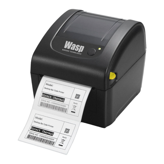
The WPL206 Series is a perfect combination of affordability with a durable and reliable design. With a cost that can’t be beat, the WPL206 series offers both 203 and 300 dots per inch print resolution with printing speeds up to a fast 6 inches per second. The large 60 watt power supply produces high quality printed labels, even at its fastest print speeds. -
Page 8: Product Features
1.2 Product Features 1.2.1 Printer Standard Features The printer offers the following standard features. Product standard feature Direct thermal printing Gap transmissive sensor (Fixed, center of offset to right 4 mm from center) Black mark reflective sensor (Fixed, center of offset to right 4 mm from center) Head open sensor 1 operation button 1 LED with 3 colors... -
Page 9: Printer Optional Features
Code page Codepage 437 (English - US) Codepage 737 (Greek) Codepage 850 (Latin-1) Codepage 852 (Latin-2) Codepage 855 (Cyrillic) Codepage 857 (Turkish) Codepage 860 (Portuguese) Codepage 861 (Icelandic) Codepage 862 (Hebrew) ... -
Page 10: General Specifications
External Bluetooth connectivity (option with RS-232) ○ 1.3 General Specifications General Specifications Physical 195 mm x 172 mm x 165 mm dimensions Note : 195 mm x 178.5 mm x 165 mm (incl. open lever) Mechanism Plastic with double-walled clamshell design Weight 1.5 kg External universal switching power supply... -
Page 11: Media Specifications
1.5 Media Specifications Media Specifications 127 mm (5“) OD Media roll capacity 1” (1.5”) ID core Media core diameter Note : 1.5’’ adapter Media type Continuous, die-cut, black mark, External fan-fold, receipt Media wound type Outside wound Media width 19 mm ~ 114 mm (0.7”~ 4.5”) Media thickness 0.055 mm ~ 0.19 mm (2.16 ~ 7.48 mil) 10 mm ~ 2,286 mm (0.39”... -
Page 12: Operations Overview
2. Operations Overview 2.1 Unpacking and Inspection This printer has been specially packaged to withstand damage during shipping. Please carefully inspect the packaging and printer upon receiving the bar code printer. Please retain the packaging materials in case you need to reship the printer. Unpacking the printer, the following items are included in the carton. -
Page 13: Printer Overview
2.2 Printer Overview 2.2.1 Front & rear Top cover open lever LED indicators Feed/Pause button External label entrance chute Power switch Power jack socket USB interface USB host (option) Ethernet interface (option) RS-232 interface (option) - 7 -... -
Page 14: Interior View
2.2.2 Interior View Print head Gap sensor (transmitter) Media viewer Media holder Platen roller Media holder lock switch Black mark sensor/ Gap sensor (receiver) - 8 -... -
Page 15: Led And Button Function
2.3 LED and Button Function This printer has one button and one three-color LED indicator. By indicating the LED with different color and pressing the button, printer can feed labels, pause the printing job, select and calibrate the media sensor, print printer self-test report, reset printer to defaults (initialization). Please refer to the button operation below and “Power-on Utilities”... -
Page 16: Setup
3. Setup 3.1 Setting up the Printer 1. Place the printer on a flat, secure surface. 2. Make sure the power switch is off. 3. Connect the printer to the computer with the provided USB cable. 4. Plug the power cord into the AC power cord socket at the rear of the printer, and then plug the power cord into a properly grounded power... -
Page 17: Loading The Media
3.2 Loading the Media 3.2.1 Loading the Roll Labels 1. Open the printer top cover by pressing up the top cover open tabs located on each side of the printer. 2. Separate the media holders to the label roll width. 3. - Page 18 4. Place the label leading edge onto the platen roller. (printing side face up) 5. Close the top cover gently and make sure the cover latches securely. 6. Use “Diagnostic Tool” to set the media sensor type and calibrate the selected sensor.
-
Page 19: Loading External Media
3.2.2 Loading External Media 1. Open the printer top cover by pressing up the top cover open tabs located on each side of the printer. 2. Separate the media holders to the label width. 3. Press down the media holder lock switch to fix the media holder. - Page 20 4. Feed the media through the rear external label entrance chute. (printing side face up) Place the label leading edge onto the platen roller. 5. Close the top cover gently and make sure the cover latches securely. 6. Use “Diagnostic Tool” to set the media sensor type and calibrate the selected sensor.
-
Page 21: Loading Media In Peel-Off Mode (Option)
3.2.3 Loading Media in Peel-off Mode (Option) 1. Please refer to section 3.2.1 to load the media. Place the label leading edge onto the platen roller. 2. Close the top cover gently. Use “Diagnostic Tool” to set the media sensor type, calibrate the selected sensor and set the post-print action to “PEEL”. - Page 22 5. Printer is ready for peel-off mode. Print a label for test. Note: * Please calibrate the gap/black mark sensor when changing media. - 16 -...
-
Page 23: Loading Media In Cutter Mode (Option)
3.2.4 Loading Media in Cutter Mode (Option) 1. Please refer to section 3.2.1 to load the media. Lead the paper through the cutter paper opening. 2. Close the top cover gently. 3. Use “Diagnostic Tool” to set the media sensor type, calibrate the selected sensor and set the post-print action to “CUTTER”. -
Page 24: Install The Adapter For 1.5" Paper Core (Option)
3.3 Install the Adapter for 1.5” Paper Core (Option) 1. Please refer to section 3.2.2 to fix the media holders for installing the 1.5” adapters. 2. Press 1.5” adapters into both media holders for using 1.5: core media roll. - 18 -... -
Page 25: Power-On Utilities
4. Power-on Utilities There are six power-on utilities to set up and test printer hardware. These utilities are activated by pressing FEED button then turning on the printer power simultaneously and release the button at different color of LED. Please follow the steps below for different power-on utilities. 1. -
Page 26: Gap/Black Mark Sensor Calibration
4.1 Gap/Black Mark Sensor Calibration Gap/black mark sensor sensitivity should be calibrated at the following conditions: 1. A brand new printer 2. Change label stock. 3. Printer initialization. Please follow the steps below to calibrate the gap/black mark sensor. 1. Turn off the power switch. 2. -
Page 27: Gap/Black Mark Calibration, Self-Test And Dump Mode
4.2 Gap/Black Mark Calibration, Self-test and Dump Mode While calibrate the gap/black mark sensor, printer will measure the label length, print the internal configuration (self-test) on label and then enter the dump mode. To calibrate gap or black mark sensor, depends on the sensor setting in the last print job. -
Page 28: Self-Test
4.2.1 Self-test Printer will print the printer configuration after media sensor calibration. Self-test printout can be used to check if there is any dot damage on the heater element, printer configurations and available memory space. Self-test printout Model name F/W version Firmware checksum Printer S/N Configuration file... - Page 29 Numbers of download files Total & available memory space Print head check pattern - 23 -...
-
Page 30: Dump Mode
4.2.2 Dump mode Printer will enter dump mode after printing printer configuration. In the dump mode, all characters will be printed in 2 columns as following. The left side characters are received from your system and right side data are the corresponding hexadecimal value of the characters. It allows users or engineers to verify and debug the program. -
Page 31: Printer Initialization
4.3 Printer Initialization Printer initialization is used to clear DRAM and restore printer settings to defaults. Printer initialization is activated by the following procedures. 1. Turn off the power switch. 2. Hold on the button then turn on the power switch. 3. -
Page 32: Set Black Mark Sensor As Media Sensor And Calibrate The Black Mark Sensor
4.4 Set Black Mark Sensor as Media Sensor and Calibrate the Black Mark Sensor Please follow the steps as below. 1. Turn off the power switch. 2. Hold on the button then turn on the power switch. 3. Release the button when LED turns green/amber after 5 green blinks. (Any green/amber will do during the 5 blinks). -
Page 33: Skip Auto.bas
4.6 Skip AUTO.BAS WPL2 programming language allows user to download an auto execution file to flash memory. Printer will run the AUTO.BAS program immediately when turning on printer power. The AUTO.BAS program can be interrupted without running the program by the power-on utility. Please follow the procedures below to skip an AUTO.BAS program. -
Page 34: Diagnostic Tool
5. Diagnostic Tool Wasp Barcode’s Diagnostic Utility is an integrated tool incorporating features that enable you to explore a printer’s settings/status; change a printer’s settings; download graphics, fonts and firmware; create a printer bitmap font; and send additional commands to a printer. With the aid of this powerful tool, you can review printer status and setting in an instant, which makes it much easier to troubleshoot problems and other issues. -
Page 35: Printer Function
5.2 Printer Function 1. Connect the printer and computer with a cable. 2. Select the PC interface connected with bar code printer. USB interface Others interface The default interface setting is USB interface. If USB interface is connected with printer, no other settings need to be changed in the interface field. -
Page 36: Setting Ethernet By Diagnostic Tool (Option)
5.3 Setting Ethernet by Diagnostic Tool (Option) The Diagnostic Utility is enclosed in the CD disk \Utilities directory or can be downloaded from www.waspbarcode.com website. Users can use Diagnostic Tool to setup the Ethernet by USB and Ethernet interfaces. The following contents will instruct users how to configure the Ethernet by these interfaces. -
Page 37: Using Rs-232 Interface To Setup Ethernet Interface
5.3.2 Using RS-232 interface to setup Ethernet interface 1. Connect the computer and the printer with a RS-232 cable. 2. Turn on the printer power. 3. Start the Diagnostic Utility by double clicks on the icon. 4. Select “COM” as interface then click on the “Setup” button to setup the serial port baud rate, parity check, data bits, stop bit and flow control parameters. -
Page 38: Using Ethernet Interface To Setup Ethernet Interface
5.3.3 Using Ethernet interface to setup Ethernet interface 1. Connect the computer and the printer to the LAN. 2. Turn on the printer power. 3. Start the Diagnostic Utility by double clicks on the icon. 4. Select “Ethernet” as the interface then click on the “Setup” button to setup the IP address, subnet mask and gateway for the on board Ethernet. - Page 39 6. Select the printer in the left side of listed printers, the correspondent IP address will be shown in the right side “IP address/Printer Name” field. 7. Click “Change IP Address” to configure the IP address obtained by DHCP or static. The default IP address is obtained by DHCP.
- Page 40 Web setup button Except to use the Diagnostic Utility to setup the printer, you can also explore and configure the printer settings and status or update the firmware with the IE or Firefox web browser. This feature provides a user friendly setup interface and the capability to manage the printer remotely over a network. - 34 -...
-
Page 41: Troubleshooting
6. Troubleshooting The following guide lists the most common problems that may be encountered when operating this bar code printer. If the printer still does not function after all suggested solutions have been invoked, please contact the Customer Service Department of your purchased reseller or distributor for assistance. -
Page 42: Print Problem
6.2 Print Problem Problem Possible Cause Recovery Procedure Check if interface cable is well Re-connect cable to interface. connected to the interface connector. The serial port cable pin configuration is Please replace the cable with pin to not pin to pin connected. pin connected. -
Page 43: Maintenance
7. Maintenance This session presents the clean tools and methods to maintain your printer. 1. Please use one of following material to clean the printer. Cotton swab Lint-free cloth Vacuum / Blower brush 100% Ethanol or Isopropyl Alcohol 2. -
Page 44: Revise History
Revise History Date Content Editor 2015/9/24 Modify section 1.4 (Max. print speed to 6” for WPL206) Camille 2016/3/29 Modify section 3.2.3 (Loading Media in Peel-off Mode) Camille 2016/7/21 Remove linerless cutter Camille Add section 1.2.2 factory option for Internal 802.11 a/b/g/n wireless module and Internal Bluetooth module 2017/5/15 Kate... - Page 46 Corporate Headquarters 1400 10th St Plano, TX 75074 TEL: 214-547-4100 Website: www.waspbarcode.com Wasp Barcode Technologies E-mail: support.waspbarcode.com...
Need help?
Do you have a question about the WPL206 Series and is the answer not in the manual?
Questions and answers