Table of Contents
Advertisement
Quick Links
PZ201E User Manual
E-617
Release: 1.1.1
Date: 2010-04-21
High-Power Piezo Amplifier
This document describes the
following product(s):
E-617.001
High-Power Piezo Amplifier with Energy Recovery,
1 Channel, 100 W, Top-Hat Rail
E-617.00F
High-Power Piezo Amplifier with Energy Recovery,
OEM Module, 1 Channel, 100 W
© Physik Instrumente (PI) GmbH & Co. KG
Auf der Römerstr. 1 ⋅ 76228 Karlsruhe, Germany
Tel. +49-721-4846-0 ⋅ Fax: +49-721-4846-299
info@pi.ws ⋅ www.pi.ws
Advertisement
Table of Contents

Subscribe to Our Youtube Channel
Related Manuals for PI E-617


Summary of Contents for PI E-617
- Page 1 1 Channel, 100 W, Top-Hat Rail E-617.00F High-Power Piezo Amplifier with Energy Recovery, OEM Module, 1 Channel, 100 W © Physik Instrumente (PI) GmbH & Co. KG Auf der Römerstr. 1 ⋅ 76228 Karlsruhe, Germany Tel. +49-721-4846-0 ⋅ Fax: +49-721-4846-299 info@pi.ws ⋅ www.pi.ws...
- Page 2 Physik Instrumente (PI) GmbH & Co. KG is the owner of the following company names and trademarks: PI®, PIC®, PICMA®, PILine®, PIFOC®, PiezoWalk®, NEXACT®, NEXLINE®, NanoCube®, NanoAutomation® The following designations are protected company names or registered trademarks of third parties:...
- Page 3 Dr. Karl Spanner President The E-617.00F OEM Module is intended to be integrated in other electrical equipment. It does not carry the CE emblem but will conform to the cited EMC Standards and normative documents providing the user ensures a compliant connection when implementing the total system.
- Page 4 About This Document Users of This Manual This manual is designed to help the reader to install and operate the E-617 High-Power Piezo Amplifier. It assumes that the reader has a fundamental understanding of motion control concepts, piezoelectric drives and applicable safety procedures.
-
Page 5: Table Of Contents
Safety Precautions ..............4 Model Survey ................5 Contents of Delivery ..............5 Additional Components ..............6 Operation E-617.001 Amplifier Module for Top-Hat Rail Mounting.....7 2.1.1 Mechanical Mounting ..............7 2.1.2 Connections ................8 2.1.3 Start-Up ..................9 2.1.4 Monitoring the Output Voltage ........... 9 E-617.00F OEM Amplifier Module..........10... -
Page 6: Introduction
Charge is transferred to the piezo actuator using low-loss PWM techniques. When the actuator is discharged, the energy not consumed is fed through the energy recovery circuitry for reuse in the next charging cycle. The working principle of the E-617 www.pi.ws E-617 PZ201E Release 1.1.1... -
Page 7: Prescribed Use
Prescribed Use Based on their design and realization, the E-617 High-Power Piezo Amplifiers are intended to drive capacitive loads, in the present case, piezoceramic actuators. The E-617 must not be used for applications other than stated in this manual, especially not for driving ohmic (resistive) or inductive loads. -
Page 8: Safety Precautions
When working with these devices or using PZT products from other manufacturers we strongly advise you to follow general accident prevention regulations. Allow operation of the E-617.00F module only after it has been installed in a proper housing which provides protection against the exposed conductors with high voltages. -
Page 9: Model Survey
Solderable socket, matching the 32-pin main connector on the module, designed for installation completely inside the user housing. See 2.2.2, p.11 for pinouts. PZ201E User Manual for E-617 (this document) E500T0011 Technical Note for Analog Driver Set www.pi.ws E-617 PZ201E Release 1.1.1... -
Page 10: Additional Components
(Driver set can also be downloaded from www.pi.ws: see included technical note E500T0011 for instructions). The E-617 can be controlled via a signal connected to its analog input line (see "Using the Analog Input" for more information). This signal can, for example, be generated using a D/A board in a PC. -
Page 11: Operation
E-617.001 Amplifier Module for Top- Hat Rail Mounting 2.1.1 Mechanical Mounting E-617.001 is designed to be mounted on a standard 35 mm top- hat mounting rail (DIN EN 50022). See Fig. 3. Fig. 3: E-617.001 rear view with detail of top-hat rail (right) www.pi.ws E-617 PZ201E Release 1.1.1... -
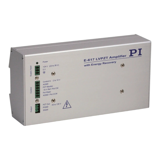
Page 12: Connections
Operation 2.1.2 Connections All electrical connections are on the front panel. Fig. 4: E-617.001 connectors (Phoenix lugs) Element / Labeling Description Connector Power The green LED indicates that the module is powered up and in operation. Supply Input / +24 V (23 to 26 V) -
Page 13: Start-Up
Operation 2.1.3 Start-Up On the main board of the E-617 modules a DC-DC converter is installed with a 23 to 26 VDC input voltage range. The converter generates -30 and +130 V for the power amplifier. Optionally, connect an external 10 k-ohm potentiometer to the control input sockets using the included 6-pin connector. -
Page 14: E-617.00F Oem Amplifier Module
All work done with and on this module requires adequate knowledge and training in handling High Voltages. Allow operation of the E-617.00F module only after it has been installed in a proper housing which provides protection against the exposed conductors with high voltages. -
Page 15: 32-Pin Main Connector
-VCC supply, 0 V (connect to 20c for minimum noise) AGND 20 c AGND 22 c AGND 24 c 26 c 28 c 30 c Protective GND 32 c Protective GND nc = not connected www.pi.ws E-617 PZ201E Release 1.1.1 Page 11... -
Page 16: System Connection Summary
32a&c 2.2.4 Start-Up On the main board of the E-617.00F module a DC-DC converter is installed with a 23 to 26 VDC input voltage range. The converter generates -37 and +137 V for the power amplifier. Connect pin 6c (control out) to pin 8c (amplifier in). -
Page 17: Monitoring The Output Voltage
DC signal in the range of -2 to +12 V (-3 to +13 V are possible but working with increased output voltage will decrease actuator lifetime, see p. 19 for details). See section 2.3.4, p.14, for information on PI support of external operation with a DAC card in a PC. 2.3.2... -
Page 18: Combining External Signal Source & Dc Offset
Computer Control & Hyperbit Computer control of an E-617 can be realized using a DAC- board in a PC to generate the analog input signal. PI offers a LabVIEW driver set which can be used with certain D/A boards. This driver set is compatible with the PI General Command Set (GCS) LabVIEW driver set available for all newer controllers from PI. -
Page 19: Technical Data
Analog / Control IN socket Phoenix-plug connector MINI-COMBICON 6-pin IMC1.5/6-ST-3.81 DC-Offset Setting 0 to 100 V at output with 0 to 100 V at output with external pot (not included) external pot (not included) www.pi.ws E-617 PZ201E Release 1.1.1 Page 15... - Page 20 (1 µF), while approx. 55 W will be available for the external piezo load. With a small-signal capacitance of 1 µF, the piezo actuator would have a large-signal capacitance of 2 µF, and approx. 67 W would be available for it. www.pi.ws E-617 PZ201E Release 1.1.1 Page 16...
-
Page 21: Operating Limits
Technical Data Operating Limits Fig. 6: E-617 open-loop frequency response with various PZT loads. Values shown are capacitance in μF. www.pi.ws E-617 PZ201E Release 1.1.1 Page 17... -
Page 22: Block Diagram
Technical Data Block Diagram Fig. 7: E-617 wiring. Pin numbers for E-617.00F are given in the drawing (see section 2.2.2, p.11, for pin assignments). Control input signals (for E-617.00F: on main connector pin 10c) and the signal from the external DC-offset potentiometer are combined in the preamplifier stage. -
Page 23: Appendix
This must always be taken into consideration in an application. The recommended maximum range of the control input voltage for E-617 therefore is -2 to 12 V, resulting in a piezo voltage range of -20 to 120 V. A control input range of -3 to 13 V is possible (results in -30 to 130 V piezo voltage), but will reduce the actuator lifetime accordingly. - Page 24 =14), 100 VDC (A =75) and 45 °C (A =100) result in an approximate MTTF of 105,000 h, i.e. more than 11 years (see markings on the diagrams). Read the “Tutorial: Piezoelectrics in Positioning” in the PI Catalog for detailed information. www.pi.ws E-617 PZ201E Release 1.1.1...
-
Page 25: How To Measure The Amplifier Output
With the E-617 amplifier output, this means that a low- frequency signal seems to be measured which is not present at all.
Need help?
Do you have a question about the E-617 and is the answer not in the manual?
Questions and answers