Table of Contents
Advertisement
Quick Links
PZ210E User Manual
E-462 Piezo Amplifier
Release: 1.1.0 Date: 20 July 2011
This document describes the following
products:
■
E-462.00
HVPZT Piezo Amplifier, 10 to 1000 V, Bench Top
■
E-462.OE1
HVPZT Piezo Amplifier Module, 10 to 1000 V,
OEM-Version
© Physik Instrumente (PI) GmbH & Co. KG
Auf der Römerstr. 1 ⋅ 76228 Karlsruhe, Germany
Tel. +49 721 4846-0 ⋅ Fax: +49 721 4846-1019
info@pi.ws ⋅ www.pi.ws
Advertisement
Table of Contents

Subscribe to Our Youtube Channel
Related Manuals for PI E-462


Summary of Contents for PI E-462
- Page 1 HVPZT Piezo Amplifier, 10 to 1000 V, Bench Top ■ E-462.OE1 HVPZT Piezo Amplifier Module, 10 to 1000 V, OEM-Version © Physik Instrumente (PI) GmbH & Co. KG Auf der Römerstr. 1 ⋅ 76228 Karlsruhe, Germany Tel. +49 721 4846-0 ⋅ Fax: +49 721 4846-1019 info@pi.ws ⋅ www.pi.ws...
- Page 2 Physik Instrumente (PI) GmbH & Co. KG is the owner of the following company names and trademarks: PI®, PIC®, PICMA®, PILine®, PIFOC®, PiezoWalk®, NEXACT®, NEXLINE®, NanoCube®, NanoAutomation® The following designations are protected company names or registered trademarks of third parties:...
- Page 3 D e c l a r a t i o n o f C o n f o r m i t y according to ISO / IEC Guide 22 and EN 45014 Manufacturer: Physik Instrumente (PI) GmbH & Co. KG Manufacturer´s Auf der Römerstrasse 1...
- Page 4 About this Document Users of This Manual This manual is designed to help the reader to install and operate the E-462 Piezo Amplifier. It assumes that the reader has a fundamental understanding of motion control concepts and applicable safety procedures.
-
Page 5: Table Of Contents
E-462.00 .................... 6 2.1.1 Front and Rear Panel Elements ............7 2.1.2 Control Signal ..................8 2.1.3 Starting Operation ................. 8 2.1.4 Power Supply for E-462.00 ..............9 E-462.OE1 ..................10 2.2.1 Connections ..................10 2.2.2 Dimensions ..................11 2.2.3 Control Signal ..................11... -
Page 6: Introduction
PCB-Mount Version for OEMs The E-462.OE1 version is fully enclosed in a metal case and designed for mounting on circuit boards. All input connections are via 6 header pins located on the bottom. The PZT (piezo) high voltage output is via a coaxial cable with LEMO connector. -
Page 7: Safety Precautions
Introduction Observe the safety precautions given in this User Manual. The E-462 is a laboratory apparatus as defined by DIN EN 61010. It meets the following minimum specifications for safe operation (any more stringent specifications in the technical data table are, of course, also met): ■... -
Page 8: Unpacking
(http://www.pi.ws). Also keep and add all further information (e.g. extended instructions or Technical Notes) to the User Manual. Unpacking Unpack the E-462 Piezo Amplifier with care. Compare the contents against the items covered by the contract and against the packing list. The following components are included:... -
Page 9: Computer Control
For several D/A boards from National Instruments, PI offers a corresponding LabVIEW driver set which is compatible with the PI General Command Set (GCS), the command set used by all PI controllers. A further option includes the patented Hyperbit technology providing enhanced system resolution. -
Page 10: Start-Up
The E-462.00 and E-462.OE1 are not equipped with active discharge circuitry but have a 5·M-ohm, 3.9·nF RC network. Therefore, PZT charge and discharge times will differ. Installation and startup procedure depends on whether the E-462.00 or the E-462.OE1 is concerned. E-462.00 DANGER—HIGH VOLTAGE... -
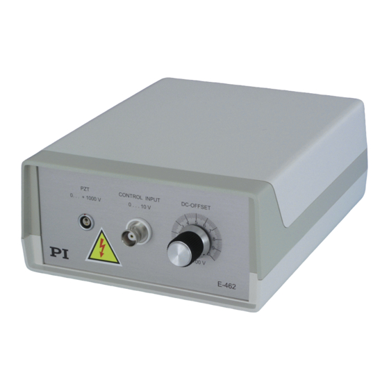
Page 11: Front And Rear Panel Elements
Start-Up 2.1.1 Front and Rear Panel Elements The E-462.00 piezo amplifier offers 1 channel with the following operating elements on the front panel: “DC-OFFSET” knob 1-turn potentiometer for DC offset (see “Control Signal” p. 8) “CONTROL INPUT” BNC Connection of control signal (see “Control socket Signal”... -
Page 12: Control Signal
Turn the “DC-OFFSET” knob fully counterclockwise (CCW). Make sure that voltage at “Control Input” is set to 0 V. Connect the E-462 to supply power. The connection is on the rear panel. Command the first motion of the piezo actuator by turning the “DC-OFFSET”... -
Page 13: Power Supply For E-462.00
2.1.4 Power Supply for E-462.00 The E-462.00 bench top unit includes a wall-plug power supply (E-660.PS) with interchangeable prong sets. Slide the appropriate prong set into the body until it clicks in place. Note that to remove a prong set it is necessary to press the plastic tab marked “Push”. -
Page 14: E-462.Oe1
During operation, do NOT touch any part which might be connected to the HV output! Make sure that your actuator and pin 3 or 5 of the E-462.OE1 are connected to a protective earth conductor. Figure 1: E-462.OE1 OEM module has HV cable on top and pins on the bottom (not shown) for PCB mounting 2.2.1... -
Page 15: Dimensions
Supply Power 12 V DC ±10 % Output reference voltage +5 V Input control voltage, 0 to 5 V Figure 2: E-462.OE1, top view, shown wired for manual operation with an external potentiometer using the on-board 5 V DC reference voltage. 2.2.2 Dimensions Figure 3: E-462.OE1, bottom view, dimensions in millimeters... - Page 16 Connect an external signal source to pins 5 and 6. ■ Interconnect pins 4, 5 and 6 via an external potentiometer as shown in Figure 2 above. This option uses the 5 V DC reference available on pin 4. www.pi.ws E-462 PZ210E Release 1.1.0 Page 12...
-
Page 17: Customer Service
Customer Service Customer Service Call your PI representative or write to info@pi.ws; please have the following information about your system ready: ■ Product codes and serial numbers of all products in the system ■ Current firmware version of the controller (if present) ■... -
Page 18: Disposal
PI equipment that was first put into circulation after 13 August 2005, free of charge. If you have such old equipment from PI, you can send it to the following address postage-free: Physik Instrumente (PI) GmbH & Co. KG Auf der Römerstr. -
Page 19: Technical Data
12 ±10 % Max. operating current Operating temperature +5°C to +50°C (over 40°C, +5°C to +50°C (over 40°C, °C range max. av. power derated max. av. power derated 10%) 10%) Power supply Wall-plug unit www.pi.ws E-462 PZ210E Release 1.1.0 Page 15... -
Page 20: Connectors
HV OUT: HV output, up to 1000 V PGND: Power ground 5.2.2 Control Input E-462.00: BNC connector, center positive E-462.OE1: header pins 5 and 6 (see p. 10) 5.2.3 Supply Power Connector E-462.00: Industry standard 2-conductor mini phone jack, tip positive, 12 VDC E-462.OE1: header pins 1 and 2 (see p.
Need help?
Do you have a question about the E-462 and is the answer not in the manual?
Questions and answers