Table of Contents
Advertisement
Quick Links
PZ127E User Manual
E-665
LVPZT Controller / Amplifier
Release: 1.7.2
Date: 2017-05-22
Physik Instrumente (PI) GmbH & Co. KG, Auf der Roemerstrasse 1, 76228 Karlsruhe, Germany
Phone +49 721 4846-0, Fax +49 721 4846-1019, Email info@pi.ws,
This document describes the
following products:
E-665.SR
LVPZT Controller, Single-Channel, for Strain
Gauge Sensor
E-665.CR
LVPZT Controller , Single-Channel, for
Capacitive Sensor
www.pi.ws
Advertisement
Table of Contents

Related Manuals for PI E-665.SR


Summary of Contents for PI E-665.SR
- Page 1 LVPZT Controller, Single-Channel, for Strain Gauge Sensor E-665.CR LVPZT Controller , Single-Channel, for Capacitive Sensor Physik Instrumente (PI) GmbH & Co. KG, Auf der Roemerstrasse 1, 76228 Karlsruhe, Germany Phone +49 721 4846-0, Fax +49 721 4846-1019, Email info@pi.ws, www.pi.ws...
- Page 2 Physik Instrumente (PI) GmbH & Co. KG is the owner of the following company names and trademarks: PI®, NanoCube®, PICMA®, PILine®, NEXLINE®, PiezoWalk®, NEXACT®, Picoactuator®, PInano®, PIMag®, Q-Motion® The following designations are protected company names or registered trademarks of third...
-
Page 3: About This Document
Controller / Amplifier as well as the installation procedures which are required to put the associated motion system into operation. Updated releases are available for download from www.pi.ws or via email: contact your Physik Instrumente Sales Engineer or write info@pi.ws. -
Page 4: Table Of Contents
4.1.1 E-665.CR Models ..............25 4.1.2 E-665.SR Models ..............26 Adjustment Elements on Main Board ........27 4.2.1 Elements on E-665.CR Models ..........27 4.2.2 Elements on E-665.SR Models ..........29 Servo and Sensor Submodules ..........29 Calibration Opening the Case ..............30 Sensor Connection and Adjustment ........ - Page 5 10.2 Frequency Response .............. 49 10.3 Pin Assignments ..............50 10.3.1 PZT Socket on E-665-CR Models ..........50 10.3.2 PZT Socket on E-665.SR Models ..........50 10.3.3 Sensor Socket on E-665.SR Models ........51 10.3.4 I/O Connector ................52 10.3.5 E-665.CN Network Cable ............53 10.3.6 E-625.CN Network Cable ............
-
Page 6: Introduction
The block diagram on p. 25 answers most questions about how the various elements interact with each other. Commands are compatible with the PI General Command Set (see the E-816 User Manual for computer interfacing and command set details). - Page 7 E-665: E-802.55 servo-control submodule With E-665.SR models only: E-801 sensor processing submodule The information given in the User Manuals of those submodules is only relevant if you should ever need to re-calibrate your system.
-
Page 8: Intended Use
PI. Observe the safety precautions given in this User Manual. If the E-665 is used in a manner not specified by PI, the protection provided by the E-665 may be impaired. E-665s meet the following minimum specifications for operation ... -
Page 9: Safety Precautions
E-665s are amplifiers generating voltages up to 130 V for driving LVPZTs. The output power may cause serious injury. Only connect original PI parts to the »PZT« socket of the E-665. All work done with and on the devices described here requires adequate knowledge and training in handling High Voltages. - Page 10 PI, otherwise internal configuration data may be destroyed by erroneous operation. If you inform PI about your application, your E-665s will be fully calibrated before being shipped. It is usually not necessary for you to do anything more than adjust the zero point before operating the system.
-
Page 11: Model Survey
The nameplate on the controller rear panel shows the model type, the internal model number (PI-NO; model type plus suffix), the serial number of the device (SN) and information about applicable line voltage and current. -
Page 12: Additional Components
Introduction Additional Components Contact your PI Sales Engineer or write info@pi.ws, if you need the following accessory: E-665.CN network cable, 0.3 m, for networking of E-665 with E- 665 (I C bus), see “Networking on I C Bus” on p. 21 for details and p. -
Page 13: Quick Start
Cable Fuse in region connector power plug CEE(7) VII H05VV-F 16A/250V 10A/250V 3G 0.75 mm BS13/13 H05VV-F 10 A 13A/250V 10A/250V 3G 1.0 mm 498G 15A/125V 10A/125V 18/3C 498G VCTF 15A/125V 7A/125V 0.75/3C www.pi.ws E-665 PZ127E Release 1.7.2 Page 10... -
Page 14: First Steps
E-665s are amplifiers generating voltages up to 130 V for driving LVPZTs. The output power may cause serious injury. Only connect original PI parts to the »PZT« socket of the E-665. All work done with and on the devices described here requires adequate knowledge and training in handling High Voltages. - Page 15 Connect a suitable signal source to the “CONTROL IN” BNC socket. This input signal is used as control input and can also be a computer-generated analog signal (e.g. from a DAQ board). You can use the PI LabVIEW Analog Driver set provided on the included E-816 CD www.pi.ws E-665 PZ127E Release 1.7.2...
- Page 16 Follow the instructions for zero-point adjustment given in Section “Open-Loop Zero-Point Adjustment” on p. 32. To avoid an overflow of the amplifier in open-loop operation, do not exceed the allowable control input range (-2 to +12 V). www.pi.ws E-665 PZ127E Release 1.7.2 Page 13...
-
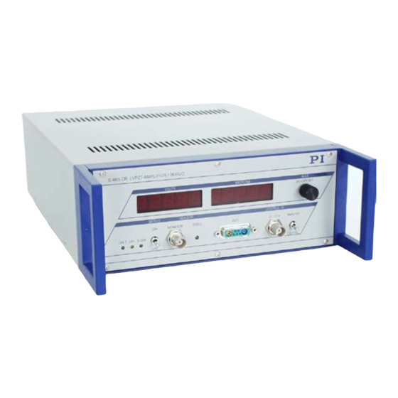
Page 17: Operation
665 supplying the required voltage on the piezo output line for the piezo to execute the commanded motion. Front and Rear Panel Elements 3.1.1 Front Panel Elements Fig. 1: E-665.CR front panel Fig. 2: E-665.SR front panel www.pi.ws E-665 PZ127E Release 1.7.2 Page 14... - Page 18 Trim pot accessible with small screwdriver for sensor zero-point adjustment. Readjustment may become necessary with time or if the load is changed. Do the adjustment with Servo OFF! See “Open-Loop Zero-Point Adjustment” on p. 32 for more details. www.pi.ws E-665 PZ127E Release 1.7.2 Page 15...
- Page 19 The control input voltage can also be a computer-generated analog signal (e.g. from a DAQ board). You can use the PI LabVIEW Analog Driver set provided on the E-816 CD to generate that analog signal. See “Control Modes” on p. 18 for details.
-
Page 20: Rear Panel Elements
Operation 3.1.2 Rear Panel Elements Fig. 3: E-665 rear panel with I/O, RS-232, USB and power connectors and fuse compartment (E-665.SR and .CR models have identical rear panels) RS-232 Serial connection to host PC. Sub-D 9 male, industry-standard RS-232. See the User Manual for E-816 Computer Interface and Command Interpreter Submodule (PZ116E) for more information. -
Page 21: Modes Of Operation
-5 to +5 V. This feature can thus be used to allow operation from a bipolar input signal. With the control input locked at 0 V, the output can be www.pi.ws E-665 PZ127E Release 1.7.2 Page 18... -
Page 22: Servo Modes (On / Off)
The analog control input can be a computer-generated analog signal (e.g. from a DAQ board). You can use the PI LabVIEW Analog Driver set provided on the E-816 CD to generate that analog signal. This driver set also includes the Hyperbit drivers which make possible position resolution higher than that of the DAQ board used. - Page 23 The servo loop thus maintains the axis position. Closed-loop operation offers both drift-free and hysteresis-free positioning as well as immunity to load variations. PI’s standard calibration procedure assures that the stage reaches its nominal displacement when that position is commanded. www.pi.ws E-665 PZ127E Release 1.7.2...
-
Page 24: Networking On I C Bus
Note the following when networking .CR models for capacitive sensors: For networking of E-665.CR with E-625.CR, use an E- 625.CN cable. The E-625.CR must be the synchronization master. The E-665.CR must be set as synchronization slave. www.pi.ws E-665 PZ127E Release 1.7.2 Page 21... - Page 25 3. Set the channel names for the individual E-665s. All devices have the name "A" by default. The master unit—the one which is connected with the host PC via the communications cable—is always addressable with the www.pi.ws E-665 PZ127E Release 1.7.2 Page 22...
- Page 26 D9 connectors which still allow access to the other signals provided by the I/O connector (for I/O connector pinout see p. 52). For further details regarding networking see the User Manual of the E-816 computer interface module. www.pi.ws E-665 PZ127E Release 1.7.2 Page 23...
-
Page 27: User Electronics And Sensor Monitor Signal
It may be necessary to add a 4.7 nF (ceramic NP0 or COC type) to the input connector. Use shielded cable if possible, otherwise make sure the lead pair is tightly twisted. Fig. 4: Electronics on Sensor Monitor line with required input capacitance www.pi.ws E-665 PZ127E Release 1.7.2 Page 24... -
Page 28: Electronics Design
Electronics Design Electronics Design Block Diagrams 4.1.1 E-665.CR Models Fig. 5: E-665.CR block diagram www.pi.ws E-665 PZ127E Release 1.7.2 Page 25... -
Page 29: E-665.Sr Models
Electronics Design 4.1.2 E-665.SR Models Fig. 6: E-665.SR block diagram www.pi.ws E-665 PZ127E Release 1.7.2 Page 26... -
Page 30: Adjustment Elements On Main Board
(p. 25). If your unit is part of a complete system with components ordered together, appropriate settings will made before shipping and may differ from the defaults. www.pi.ws E-665 PZ127E Release 1.7.2 Page 27... - Page 31 Sensor gain adjustment P301 See “Calibration” on p. 30 for details Integrated Linearization System (ILS) P303 See “Second Order Polynomial Linearization adjustment for minimizing second-order (E-665.CR only)” on p. 37 for details polynomial non-linearity www.pi.ws E-665 PZ127E Release 1.7.2 Page 28...
-
Page 32: Elements On E-665.Sr Models
Electronics Design 4.2.2 Elements on E-665.SR Models All elements which can be subject to custom adjustment are on the E-801 and E-802 submodules. See the corresponding User manuals, “Calibration” on p. 30 and “Servo and Sensor Submodules” on p. 29 for details. -
Page 33: Calibration
Sensor Connection and Adjustment If you inform PI about your application, your E-665s will be fully calibrated before being shipped. It is usually not necessary for you to do anything more than adjust the zero point before operating the system. - Page 34 The E-665.CR provides sensor processing for capacitive sensors. Models with the E-801 submodule (E-665.SR) can be set up to accept an externally provided sensor signal from 0-10 V. See the E-801 User Manual for details. The output from the sensor-readout electronics is an analog signal that is directly proportional to the displacement of the stage and is available at “SENSOR MONITOR”...
-
Page 35: Open-Loop Zero-Point Adjustment
OFFSET” potentiometer must be turned fully counterclockwise) Read the corresponding sensor position shown on the “MICRONS” front panel display Adjust the “SENSOR ZERO” potentiometer on the front panel so that the “MICRONS” display is +1 V www.pi.ws E-665 PZ127E Release 1.7.2 Page 32... -
Page 36: Open-Loop Sensor Range (Gain) Adjustment
High Voltages and should be carried out by authorized, qualified personnel only. When the unit must be operated with the case open, voltages of up to 130 V can be exposed. Do not touch internal conductors. www.pi.ws E-665 PZ127E Release 1.7.2 Page 33... - Page 37 MONITOR” socket) is 10 V. To do this, with E-665.CR models use the P301 adjustment potentiometer on the main board (see p. 27). With E-665.SR models, the adjustment potentiometer is on the E-801 sensor submodule, see the E-801 User Manual for details.
-
Page 38: Static Gain Adjustment For Closed-Loop Operation
High Voltages and should be carried out by authorized, qualified personnel only. When the unit must be operated with the case open, voltages of up to 130 V can be exposed. Do not touch internal conductors. www.pi.ws E-665 PZ127E Release 1.7.2 Page 35... - Page 39 This adjustment can only be done accurately for one control mode (analog mode or computer-controlled mode). If you use the unadjusted mode, 1% error in the sensor monitor output voltage can be expected. www.pi.ws E-665 PZ127E Release 1.7.2 Page 36...
-
Page 40: Second Order Polynomial Linearization (E-665.Cr Only)
(with the “DC-OFFSET” potentiometer turned fully counterclockwise) and read the stage displacement using an external gauge. Alternatively, you can turn the “DC-OFFSET” potentiometer fully clockwise (with the analog input signal = 0 V) www.pi.ws E-665 PZ127E Release 1.7.2 Page 37... -
Page 41: Servo-Control Dynamic Characteristics
Note that the notch filter and slew rate limiter are not deactivated when switching the servo mode off. Resetting the notch filter frequency in open-loop operation can cause the piezo output voltage to change by as much as 5%. www.pi.ws E-665 PZ127E Release 1.7.2 Page 38... -
Page 42: Maintenance
2 x IEC 0.8AT, 250 VAC* 115 VAC 2 x IEC 1.6AT, 125 VAC or 2 x IEC 1.6AT, 250 VAC* * Unless otherwise noted on the type label on the rear panel of the E-665 chassis. www.pi.ws E-665 PZ127E Release 1.7.2 Page 39... - Page 43 (115 V or 230 V) can be seen through the window when the door is closed. Reinstall the carrier and close the door. Fig. 9: Fuse location on the rear panel and in the carrier (1 of 2 fuses visible) www.pi.ws E-665 PZ127E Release 1.7.2 Page 40...
-
Page 44: Transformer Secondary Winding Fuses
See figure below for the required fuse ratings; all are T-class (slow blow) fuses: Fig. 10: Fuses for transformer secondary windings on the E-665 board www.pi.ws E-665 PZ127E Release 1.7.2 Page 41... -
Page 45: Troubleshooting
0 to 10 V (excursions to -2 or +12 V may cause overflow, especially with servo on, and reduce the lifetime of the piezo actuator). The analog control signal can be shifted by 0 to 10 V using the “DC_OFFSET” potentiometer. www.pi.ws E-665 PZ127E Release 1.7.2 Page 42... - Page 46 Troubleshooting If you generate the analog signal with a DAQ board in a PC running LabVIEW and using PI’s LabVIEW Analog Driver Set, check the driver and the DAQ board for proper operation. Move commands or wave table commands may provoke errors and are ignored.
- Page 47 You can, for example, test the communication by simply starting a terminal program, e.g. PI Terminal, and entering *IDN?. Note that multi-character commands are transferred as terminated by a LF (line feed) character and are executed only after the LF is received.
- Page 48 Permanent glow of the “OFL” LED in spite of zero point adjustment may indicate hardware failure. Contact your Physik Instrumente Sales Engineer. Custom software accessing PI drivers does not run. Wrong combination of driver routines/Vis Check if system runs with Terminal program. If yes read the software manual and compare sample code from the E-816 CD to check the necessary driver routines.
-
Page 49: Customer Service
Customer Service Customer Service Call your PI representative or write to info@pi.ws; please have the following information about your system ready: Product codes and serial numbers of all products in the system Current firmware version of the controller (if present) ... -
Page 50: Old Equipment Disposal
PI equipment that was first put into circulation after 13 August 2005, free of charge. If you have such old equipment from PI, you can send it postage-free to the following address: Physik Instrumente (PI) GmbH & Co. KG Auf der Roemerstr. -
Page 51: Technical Data
Technical Data Technical Data 10.1 Specifications E-665.SR / E-665.CR Function Piezo amplifier & position servo-controller with digital interface Axes Sensor Servo characteristics P-I (analog), notch filter Sensor type SGS (.SR) / capacitive (CR) Amplifier Control input voltage range -2 to +12 V... -
Page 52: Frequency Response
115 VAC / 230 VAC, 50-60 Hz (linear power supply) Max. power consumption 60 W 10.2 Frequency Response Fig. 11: E-665 open-loop frequency response with various PZT loads. Capacitance values are in µF. www.pi.ws E-665 PZ127E Release 1.7.2 Page 49... -
Page 53: Pin Assignments
AGND target and ID GND PZT GND (tied to case) n.c. Sensor target 10.3.2 PZT Socket on E-665.SR Models LEMO socket ERA.00.250, 2-pin, for transmission of the piezo voltage: Outer contact: PZT ground (connected with the case) Inner contact: PZT+ (–30 to +130 V) www.pi.ws... -
Page 54: Sensor Socket On E-665.Sr Models
LEMO socket EPL.0S.304.HLN, 4-pin, for transmission of the sensor signal from the stage. The pin assignment depends on the sensor wiring in the stage: Fig. 12: SGS sensor wiring with various PI stages www.pi.ws E-665 PZ127E Release 1.7.2 Page 51... -
Page 55: I/O Connector
****Active HIGH; LOW: 0 to 0.5 V, HIGH: 3.0 to 5.0 V, maximum 10 V; max. freq. 400 Hz; min. width: 5 μs. In computer-controlled mode, this signal is used as trigger input for wave table operation and triggered motion. Fig. 13: DB-9f I/O Connection www.pi.ws E-665 PZ127E Release 1.7.2 Page 52... -
Page 56: E-665.Cn Network Cable
Technical Data 10.3.5 E-665.CN Network Cable Fig. 14: E-665.CN network cable for networking of E-665 with E-665 10.3.6 E-625.CN Network Cable Fig. 15: E-625.CN network cable for networking of E-625.CR with E-665.CR www.pi.ws E-665 PZ127E Release 1.7.2 Page 53... -
Page 57: Appendix
지역에서 사용하는 것을 목적으로 합니다. This equipment complies with class A of the KC rule. Distributors or users should be aware of this with a caution, and it is for using out of homes. www.pi.ws E-665 PZ127E Release 1.7.2 Page 54...
Need help?
Do you have a question about the E-665.SR and is the answer not in the manual?
Questions and answers