
Related Manuals for Gotting HG G-19603ZA


Summary of Contents for Gotting HG G-19603ZA
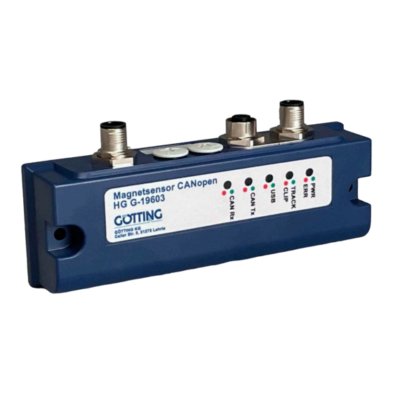
- Page 1 Magnet Magnet Sensor HG G-19603ZA Track Guidance along Magnetic Tape | CAN Interface English, Revision 03 Date: 31.03.2021 Dev. by: TE Author(s): RAD / GW Innovation through Guidance www.goetting-agv.com...
- Page 2 • Display of operating status via 5 LEDs © 2021 Götting KG, errors and modifications reserved. The Götting KG in D-31275 Lehrte has a certified quality management system according to ISO 9001. Device Description HG G-19603ZA | English, Revision 03 | Date: 31.03.2021...
-
Page 3: Table Of Contents
Receiving Box ........................32 Transmitter Box ........................33 CANopen® Interface ............... 34 Description of the Process Data Objects (PDOs) ............34 8.1.1 Transmission Objects ....................34 8.1.2 Reception Object ......................35 Device Description HG G-19603ZA | English, Revision 03 | Date: 31.03.2021... - Page 4 List of Figures.................. 45 List of Tables ...................46 Index ....................47 Copyright and Terms of Liability............ 49 15.1 Copyright ..........................49 15.2 Exclusion of Liability ......................49 15.3 Trade Marks and Company Names ................49 Device Description HG G-19603ZA | English, Revision 03 | Date: 31.03.2021...
-
Page 5: About This Document
danger. The paragraph consequences describes the consequences of not observing the warning notice. danger prevention The paragraphs for explain, how to avoid the danger. Device Description HG G-19603ZA | English, Revision 03 | Date: 31.03.2021... -
Page 6: Symbols
Whenever the pressing of letter keys is required for program entries, the required etter eys are indicated as such (for any programs of Götting KG small and capital letters are equally working). Device Description HG G-19603ZA | English, Revision 03 | Date: 31.03.2021... -
Page 7: Introduction
2.3 Intended Use The magnet sensor HG G-19603ZA is intended for the track guidance of automated guided vehicles (AGV) along magnetic tape. The sensor detects the magnetic field above magnetic tape in vertical and horizontal direction and thus continually deter- mines the actual deviation from the center of the track (center of the magnetic tape). - Page 8 The magnet sensor is only used according to section 2.1 on page 7. The magnet sen- sor is only mounted, configured, commissioned, operated, maintained and dis- mounted by personnel according to section 2.2 on page 7. Device Description HG G-19603ZA | English, Revision 03 | Date: 31.03.2021...
-
Page 9: Functional Principle
The current deviation from the center of the selected track and the current level of the magnetic field are output via the CAN/CANopen® interface. Additionally a detect signal is generated when a magnetic tape is detected underneath the sensor. Device Description HG G-19603ZA | English, Revision 03 | Date: 31.03.2021... -
Page 10: Figure 3 Signal Paths Of The Outputs (Idealized Diagram)
Dependence of the output on the height above the magnetic tape Figure 4 Height 30mm Height 40mm Height 50mm Height 60mm Height 70mm ‐5 ‐10 ‐15 Position of the track [mm] Device Description HG G-19603ZA | English, Revision 03 | Date: 31.03.2021... -
Page 11: Mounting
Mounting 3.1 Magnetic Tape For the operation of the magnet sensor HG G-19603ZA axially polarized magnetic band is to be used. The direction of the polarization can be configured s. Figure 20 on page 28). The polarization has to be identical for a whole facility. -
Page 12: Magnetic Tape Installation
Those divert the magnetic field and distort the readings. Similarly an area with a diameter of approximately the nominal reading height around the mag- netic tape should be free of ferromagnetic materials. Device Description HG G-19603ZA | English, Revision 03 | Date: 31.03.2021... -
Page 13: Mounting On The Vehicle
We recom- mend using a mounting bracket or mounting plate, e.g. made from Aluminium or acrylic glass (e.g. Plexiglas®), see Figure 8 below. Device Description HG G-19603ZA | English, Revision 03 | Date: 31.03.2021... -
Page 14: Connection Cable (Assembled On One Side)
Plug M12 5 pin, A coded HW CON00100 CAN1: Closing plug M12 5 pin, A coded, shieldable HW CAB00064 CAN2: CAN Bus cable, 10 m, with shielding, one-sided M12 socket straight Device Description HG G-19603ZA | English, Revision 03 | Date: 31.03.2021... -
Page 15: Commissioning
-0.003369 [mT] -0.033130 [mT] 0.006274 [mT] track (C) calibration detect (D) load default settings (S) save settings sum of flux density: 0.160 (F) firmware update (ESC) QUIT (ESC) QUIT Device Description HG G-19603ZA | English, Revision 03 | Date: 31.03.2021... -
Page 16: Table 4 Thresholds For Two Magnetic Tracks With Standard Magnetic Tapes
CANopen® interface (see chapter 7 on page 32 / 8 on page 34) or for testing via the manual control in the main menu, see Figure 16 on page 25. Device Description HG G-19603ZA | English, Revision 03 | Date: 31.03.2021... -
Page 17: Compensation Of Permanent Magnetic Interferences
TURN ON static filed please REMOVE all track form the sensor please REMOVE all track form the sensor Key 1 (1) continue (1) continue (ESC) abourt (ESC) abourt (ESC) QUIT (ESC) QUIT Device Description HG G-19603ZA | English, Revision 03 | Date: 31.03.2021... -
Page 18: Deleting The Compensation
TURN ON static field if static field is compansated please PLACE one track under the center of the sensor calibration (1) continue (ESC) abourt Device Description HG G-19603ZA | English, Revision 03 | Date: 31.03.2021... - Page 19 interferences are present. Confirm with continue that the sensor is placed centered above a single track. The following parameters are automatically configured: sensitivity, sen. two tracks. Device Description HG G-19603ZA | English, Revision 03 | Date: 31.03.2021...
-
Page 20: Hardware
USB connection is established – blinks for active communication via the USB interface CAN Tx green blinks when sending CAN messages CAN Rx green blinks when receiving CAN messages Device Description HG G-19603ZA | English, Revision 03 | Date: 31.03.2021... -
Page 21: Pin Assignment
5 pin M 12 male connector (A coded) Pin assignment ST 1 5 pin Table 6 ST 1 Signal Annotation +Ub (24V) supply voltage — n.c. M12, 5-Pin, male Ground (Supply and USB) Device Description HG G-19603ZA | English, Revision 03 | Date: 31.03.2021... -
Page 22: Can1/Can2
Crossroads thus have to be realized with the left turnoff and the right turnoff having an offset. Layout of turnoffs Figure 14 Turnoff selection Magnet sensor Direction left of travel left straight straight right right straight right Device Description HG G-19603ZA | English, Revision 03 | Date: 31.03.2021... - Page 23 As shown in Figure 14 at turnoffs the direction should either be set to the direction of the turnoff or the opposite direction. Since there is no turnoff in the opposite di- rection the sensor then steers the vehicle straight on. Device Description HG G-19603ZA | English, Revision 03 | Date: 31.03.2021...
-
Page 24: Software
If the magnet sensor is not automatically detected as a virtual COM port after estab- lishing the connection the STM32 Virtual COM Port Driver (STSW-STM32102) has to be installed manually. Device Description HG G-19603ZA | English, Revision 03 | Date: 31.03.2021... -
Page 25: Terminal Program
The service program shows the current system status. In its first line the serial num- ber and the software version are output. Below a visual representation of the sensor casing follows that shows the position of detected magnetic tapes. Device Description HG G-19603ZA | English, Revision 03 | Date: 31.03.2021... -
Page 26: Status Output
Current CAN status s. 7.2 on page 33 (CAN) / 8.1.1 on page 34 (CANopen®) Received CAN command s. 7.1 on page 32 (CAN) / 8.1.2 on page 35 (CANopen®) Device Description HG G-19603ZA | English, Revision 03 | Date: 31.03.2021... -
Page 27: 1) Csv Output
Figure 18 Counter;System1_X;System1_Y;System1_Z;System2_X;System2_Y;System2_Z;System3_X;System3_Y;System3_Z; total_field;OutputX;OutputZ;Status;Command;SN: 123456;SW: V1.01 1;0.046216;0.056738;0.209595;-0.110986;-0.001782;0.090698;-0.080127;-0.018408;- 0.037207;0.456;8.47;0.9;0x01;0x00;; 2;0.070166;0.056494;0.196924;-0.104712;-0.000635;0.112964;-0.087817;-0.016992;- 0.029785;0.465;7.22;1.12;0x01;0x00;; 3;0.088574;0.056445;0.181519;-0.095068;0.000537;0.132764;-0.094971;-0.015723;- 0.021704;0.472;5.94;1.32;0x01;0x00;; 4;0.104004;0.056348;0.163037;-0.080957;0.002515;0.151562;-0.102222;-0.013745;- 0.011841;0.477;4.55;1.51;0x01;0x00;; 5;0.113892;0.056665;0.145947;-0.066284;0.003906;0.165088;-0.10791;-0.012378;- 0.002197;0.48;3.39;1.65;0x01;0x00;; 6;0.120654;0.056641;0.127979;-0.049121;0.005859;0.176367;-0.113037;- 0.010254;0.008447;0.482;2.4;1.76;0x01;0x00;; 7;0.12395;0.05708;0.1146;-0.034937;0.007715;0.182764;-0.116382;- 0.008569;0.017334;0.482;1.73;1.82;0x01;0x00;; 8;0.125952;0.057251;0.098682;-0.017065;0.009814;0.187866;-0.119409;- 0.006274;0.028833;0.482;0.99;1.87;0x01;0x00;; 9;0.12627;0.057739;0.084595;-0.000342;0.011841;0.190186;-0.121411;- 0.004199;0.039893;0.481;0.37;1.9;0x01;0x00;; 10;0.124609;0.057788;0.068481;0.021411;0.013574;0.190186;-0.122534;-0.001904;0.055347;0.48;- 0.39;1.9;0x01;0x00;; 11;0.121265;0.057129;0.052466;0.043384;0.015259;0.185986;-0.121631;0.000928;0.071631;0.477;- 1.21;1.85;0x01;0x00;; (...) Device Description HG G-19603ZA | English, Revision 03 | Date: 31.03.2021... -
Page 28: 2) Settings
6.4.4 on page 29 reset parameters to factory settings save settings permanently firmware update (see section 6.4.6 on page 30) Device Description HG G-19603ZA | English, Revision 03 | Date: 31.03.2021... -
Page 29: C) Calibration Settings
-0.003027 [mT] -0.033276 [mT] 0.006372 [mT] track detect sum of flux density: 0.159 (ESC) QUIT CAN Status: Rx: 172 Tx: 133 OutX: 7.50 OutZ: 1.26 Out: 0x01 In: 0x00 Device Description HG G-19603ZA | English, Revision 03 | Date: 31.03.2021... -
Page 30: Firmware Update
As shown the DFU mode has to be active Use Choose to select the .dfu file If the status bar says File correctly loaded start the firmware update with Upgrade. Device Description HG G-19603ZA | English, Revision 03 | Date: 31.03.2021... -
Page 31: Figure 25 Firmware Update - Start Update
Leave DFU mode and Quit the program Afterwards the connection in the terminal program can be re-established. Then start the service program again. The firmware update is finished. Device Description HG G-19603ZA | English, Revision 03 | Date: 31.03.2021... -
Page 32: Can Bus Interface
CAN: Structure of the CAN receiving box Table 10 Byte Data Command, see Table 11 below – Annotations for Command: CAN: Structure of the command byte Table 11 Description left Track right Track – Device Description HG G-19603ZA | English, Revision 03 | Date: 31.03.2021... -
Page 33: Transmitter Box
– – Cycle counter CAN: Structure of the system status byte Table 13 Status Bit Description Track Detect Track Left Track Right Error Clip Error System – – – Device Description HG G-19603ZA | English, Revision 03 | Date: 31.03.2021... -
Page 34: Canopen® Interface
– – Cycle counter CANopen®: Structure of the system status (part 1 of 2) Table 15 Status Bit Description Track Detect Track Left Track Right Error Clip Error System Device Description HG G-19603ZA | English, Revision 03 | Date: 31.03.2021... -
Page 35: Reception Object
The identifiers for read and write access are: Reading access: 0x600 + Node - Adresse, Writing access: 0x580 + Node - Adresse. Device Description HG G-19603ZA | English, Revision 03 | Date: 31.03.2021... -
Page 36: Object Directory
Number of Entries of Device Name Device Name 1 Device Name 2 Device Name 3 0x1009 Hardware Version 0x100A 0 Software Version 0x1010 Number of entries of Save Parameter Save all Device Description HG G-19603ZA | English, Revision 03 | Date: 31.03.2021... - Page 37 Specification of Appl. Object 2 Specification of Appl. Object 3 Specification of Appl. Object 4 *) Here only the highest bit can be changed in order to temporarily (de-)activate the PDO. Device Description HG G-19603ZA | English, Revision 03 | Date: 31.03.2021...
-
Page 38: Standardized Device Profile Range
ID = 0x80 8.4.3.4 Device Name CANopen®: Device Name Table 25 Index Sub Index Name Type Attr. Map Default Meaning 0x1008 Device Name Vis.-String „1960“ Name of the device Device Description HG G-19603ZA | English, Revision 03 | Date: 31.03.2021... -
Page 39: Hardware Version
Number of sub indexes Parameter COB-ID Unsigned 32 RW NO 0x40000200 + RPDO valid, ID = 0x200 Node ID + Node ID Transmission Unsigned 8 Asynchronous, event- Type driven Device Description HG G-19603ZA | English, Revision 03 | Date: 31.03.2021... -
Page 40: Mapping Rpdo_1
Unsigned 8 0x60000108 mapped to Index object 0x6000,01 with 8 Bit length (Status) 4th mapped Unsigned 8 0x6F200108 mapped to Index object 0x6F20,01 with 8 Bit length (transmission counter) Device Description HG G-19603ZA | English, Revision 03 | Date: 31.03.2021... -
Page 41: Bit Digital Input (Transmitted In Txpdo 1)
Attr. Map Default Meaning 0x6F20 00 number of 8 bit Unsigned 8 RO 0x01 number of 8 bit inputs Life Counter 8 bit Life Unsigned 8 RO Transmission counter Counter Device Description HG G-19603ZA | English, Revision 03 | Date: 31.03.2021... -
Page 42: Maintenance
If necessary update the firmware as shown in section 6.4.6 on page 30). Date and version of the firmware are shown in the main menu (Figure 16 on page 25). Device Description HG G-19603ZA | English, Revision 03 | Date: 31.03.2021... -
Page 43: Trouble Shooting
0x10 ERROR_I2C_STOP internal error: Communication – restart device – if the error does not disappear after this: contact service Device Description HG G-19603ZA | English, Revision 03 | Date: 31.03.2021... -
Page 44: Technical Data
Repeatability: 0.05 of the output (without external inter- ferences) Working range – Height above magnetic tape: 40 to 70 mm – Detection range track: ±80 mm – Effective detection range track: ±55 mm Device Description HG G-19603ZA | English, Revision 03 | Date: 31.03.2021... -
Page 45: List Of Figures
Figure 23 Menu firmware update .........................30 Figure 24 Firmware Update – Choose file ....................30 Figure 25 Firmware Update – Start update....................31 Figure 26 Firmware Update – Leave DFU Mode ...................31 Device Description HG G-19603ZA | English, Revision 03 | Date: 31.03.2021... -
Page 46: List Of Tables
CANopen®: 32 Bit Analog Inputs (transmitted in TxPDO 1)........41 Table 37 CANopen®: 8 Bit Life Counter (transmitted in TxPDO 1)..........41 Table 38 Error codes............................43 Table 39 Technical Data ..........................44 Device Description HG G-19603ZA | English, Revision 03 | Date: 31.03.2021... -
Page 47: Index
..................21 Main menu ..................25 Copyright ..................49 Main Track..................22 CSV Output..................27 maintenance..................42 maintenance-free................42 metal-free ..................12 detection range................10 Mounting...................11 detection systems................9 mounting drill holes ..............13 DfuSE ....................30 Device Description HG G-19603ZA | English, Revision 03 | Date: 31.03.2021... - Page 48 RAW data monitor ................29 USB Interface ..................24 Service Program ................25 virtual COM Port driver ...............24 Settings....................28 Voltage curves ................10 Software....................24 spreadsheet application .............28 Status displays................26 Warning Notices ................5 Status line ..................26 Device Description HG G-19603ZA | English, Revision 03 | Date: 31.03.2021...
-
Page 49: Copyright And Terms Of Liability
Unless stated otherwise, the herein mentioned logos and product names are legally protected trade marks of Götting KG. All third party product or company names may be trade marks or registered trade marks of the corresponding companies. Device Description HG G-19603ZA | English, Revision 03 | Date: 31.03.2021... - Page 50 Innovation through Guidance Götting KG Celler Str. 5 | D-31275 Lehrte Tel. +49 (0) 5136 / 8096 -0 Fax +49(0) 5136 / 8096 -80 info@goetting-agv.com www.goetting-agv.com www.goetting-agv.com...
Need help?
Do you have a question about the HG G-19603ZA and is the answer not in the manual?
Questions and answers