Table of Contents
Advertisement
Quick Links
Guide Wire
Inductive Guidance Sensor, Multifrequency, USB
HG G-193x0-B
Inductive track guidance along a guide wire / energy track, Variants
HG G-19370: 20/25 kHz Energy Track, ZB: CAN-Bus, YB: Profinet
HG G-19380: 140 kHz Energy Track, ZB: CAN-Bus, YB: Profinet
English, Revision 02
Date: 07.05.2018
Dev. by: LF
Author(s): RAD
Innovation through Guidance
www.goetting-agv.com
Advertisement
Chapters
Table of Contents

Related Manuals for Gotting HG G-193 0-B Series


Summary of Contents for Gotting HG G-193 0-B Series
- Page 1 Guide Wire Inductive Guidance Sensor, Multifrequency, USB HG G-193x0-B Inductive track guidance along a guide wire / energy track, Variants HG G-19370: 20/25 kHz Energy Track, ZB: CAN-Bus, YB: Profinet HG G-19380: 140 kHz Energy Track, ZB: CAN-Bus, YB: Profinet English, Revision 02 Date: 07.05.2018 Dev.
- Page 2 Overview Summary Characteristics of the inductive guidance sensor HG G-193x0-B: • 5 programmable simultaneously usable • Reading height: 40 – 200 mm, nominal frequencies (2 – 20 kHz) reading height 60 mm, customizable via programmable gain • alternatively track guidance along an existing ground installation for the con- •...
-
Page 3: Table Of Contents
Table of Contents Contents 1 About this Document ................5 Function ..........................5 Symbols ..........................5 2 Introduction..................... 7 Variants/Versions ........................ 7 Range of Use ........................7 Qualification of the Users....................8 Intended Use ........................8 Functional Principle ......................9 3 Mounting .................... - Page 4 Table of Contents 7 CAN Bus Communication (HG G-193x0ZB) ........26 Telegrams ........................... 26 Control and Status Telegrams..................27 7.2.1 Incoming Telegram (IN) .......................27 7.2.2 Outgoing Telegram OUT1 ......................27 8 Profinet Communication (HG G-193x0YB) ........28 Input Bytes ......................... 28 Status/Detect (Byte 24) ....................
-
Page 5: About This Document
About this Document – Chapter 1 About this Document 1.1 Function This device description contains information regarding the correct mounting, electric instal- lation, commissioning and maintenance of the inductive guidance sensor HG G-193x0-B for the technical personnel of a manufacturer who wants to integrate the sensor into an auto- mated guided vehicle (AGV). - Page 6 Chapter 1 – About this Document Link Indicates additional information in the internet, e.g. on our homepage www.goetting- agv.com. Those links are clickable in the PDF version of this documentation. Program texts and variables are indicated through the use of a fixed width font ...
-
Page 7: Introduction
Introduction – Chapter 2 Introduction The inductive guidance sensor HG G-193x0-B is used for the inductive track guidance of Automated Guided Vehicles (AGV). Up to 5 different guide wire frequencies may be detect- ed and evaluated simultaneously. Alternatively a ground installation for the contact-less in- ductive energy transmission with two wires (from here on also energy track) can be used for the track guidance. -
Page 8: Qualification Of The Users
Chapter 2 – Introduction 2.3 Qualification of the Users The personnel intended to operate the inductive guidance sensor • has been provided with this documentation. • is familiar with the functionality of the inductive guidance sensor. • is trained sufficiently in mounting and configuring the inductive guidance sensor and qualified to perform those tasks. -
Page 9: Functional Principle
Introduction – Chapter 2 2.5 Functional Principle Note The functional principle below is explained using a guide wire installation. An energy track installation has slightly different voltage curves but the basic principle is the same. A frequency generator feeds a current into a guide wire installed in the ground. Along this wire an alternating magnetic field is generated. - Page 10 Chapter 2 – Introduction Due to the two coils the sum voltage may show two maxima. This depends on the distance to the guide wire. The sum voltage is solely used to detect a guide wire (Detect signal). For this a detector circuit is implemented. The detector sets the Detect signal to 1 for valid fre- quencies if the sum voltage exceeds a defined threshold.
-
Page 11: Mounting
Mounting – Chapter 3 Mounting 3.1 Guide Wire The guidelines for the ground installation of guide wires are explained in a separate docu- ment. You can download the PDF file from the following address (section Application Ex- amples and Downloads): Link http://www.goetting-agv.com/components/inductive/introduction 3.2 Energy Track... -
Page 12: Mounting On The Vehicle
Chapter 3 – Mounting 3.3.2 Mounting on the Vehicle 156,5 Mounting Drill Holes ø 5,3 mm M12x1 circular connector Lower edge of the device M12 circular connector BUS 1 8 in -p (male) depending on the bus type A-coded M12 circular connector BUS 2 depending on the bus type Casing dimensions and mounting drill holes (all variants) Figure 3... -
Page 13: Connection Cables (Assembled On One Side) / Terminating Resistors
Mounting – Chapter 3 3.3.3 Connection Cables (assembled on one side) / Terminating Resistors Continue by connecting the sensor to the vehicle control. For this you can use the connec- tors ST 1, ST 2 and ST 3. The pin assignment is shown in section 5.1.2 on page 15 so that you can make matching cables yourself that fit onto the standard M 12 connectors. -
Page 14: Commissioning
Chapter 4 – Commissioning Commissioning The inductive guidance sensor is pre-configured for a reading height of 60 mm and the fre- quencies ordered by the customer. Thus it can theoretically be used without an explicit commissioning. The configuration has to be changed if the CAN bus version HG G-193x0ZB is used or an incremental encoder is to be connected. -
Page 15: Hardware
Hardware – Chapter 5 Hardware 5.1 HG G-193x0ZB (CAN Bus) 5.1.1 LEDs Five LEDs allow a function check. HG G-19370ZB (CAN): Position of the LEDs Figure 5 Function lit when operating voltage is connected Track Detect, lit when a track is detected (sum voltage higher than con- figured threshold) lit for CAN bus errors –... -
Page 16: St 2 / St 3 (Can 1 / Can 2)
Chapter 5 – Hardware M12 x 1 circular connector M12 x 1 circular connector M12 x 1 circular connector 8 pin (male, A coded) 5 pin (female, A coded) 5 pin (male, A coded) ST 2 / CAN 1 ST 3 / CAN 2 HG G-193x0ZB (CAN): Position of the connectors Figure 6 5.1.2.1 ST 1... -
Page 17: Hg G-193X0Yb (Profinet)
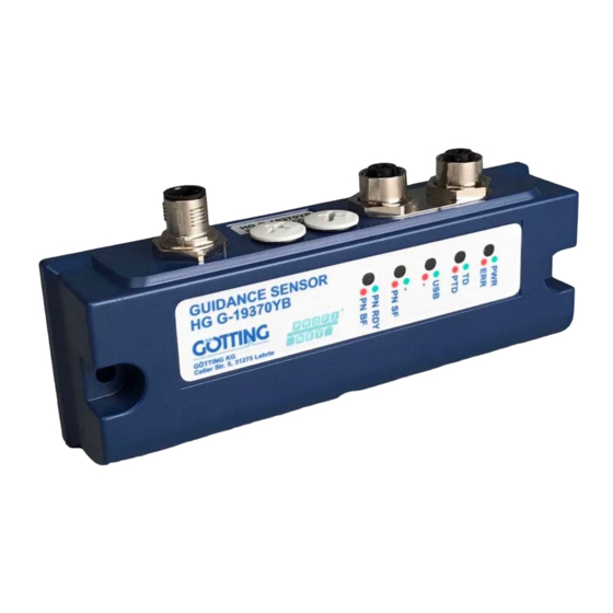
Hardware – Chapter 5 5.2 HG G-193x0YB (Profinet) 5.2.1 LEDs Five LEDs allow a function check. HG G-193x0YB (Profinet): Position of the LEDs Figure 7 Function lit when operating voltage is connected lit for errors (overmodulation of the amplifiers) Track Detect, lit when a guide wire is detected (sum voltage higher than configured threshold) lit when an energy track is detected lit when a PC is connected (see section 6.2 on page 19) -
Page 18: St 2 / St 3 (Bus 1 / Bus 2)
Chapter 5 – Hardware M12 x 1 circular connector M12 x 1 circular connector M12 x 1 circular connector 8 pin (male, A coded) 4 pin (female, D coded) 4 pin (female, D coded) ST 1 ST 2 / BUS 1 ST 3 / BUS 2 HG G-193x0YB (Profinet): Position of the connectors Figure 8... -
Page 19: Configuration
Configuration – Chapter 6 Configuration 6.1 Turn-On Characteristic The device is functional directly after switching it on (by connecting the operating voltage). It is ready to receive and send bus messages or to be configured via the USB interface. 6.2 Connection to a PC via the USB Interface The inductive guidance sensor is equipped with a USB interface for the diagnosis, configu- ration and the update of its internal firmware. -
Page 20: Service Program
Chapter 6 – Configuration 6.4 Service Program When the connection inside the Terminal Program (see above) is successfully established press any key to make the following main menu appear. 6.4.1 Main Menu The main menu differs for the sensor versions. For version HG G-193x0ZB an additional CAN menu is available. -
Page 21: 1) Frequency Config
Configuration – Chapter 6 • Firmware Update, s. section 6.4.5 on page 23 6.4.2 (1) Frequency Config Definition of the six frequencies for which the sum and difference signals are calculated. All sub menus may be quit by pressing any key that is not used in the respective menu. HG 19370 xB V1.01 Frequency Config Goetting KG... -
Page 22: 3) Encoder Config
Chapter 6 – Configuration : Gain 1 and Gain 2 set the gain for the induced voltages in the two coils. 0 is the min- imum gain, 255 is the maximum value. This gain only relates to guide wire guidance. The induced voltage depends on the current in the guide wire and the distance between sensor and guide wire. -
Page 23: 4) Csv
Configuration – Chapter 6 6.4.5 (4) CSV Serial output of the sum and difference signals as Comma Separated Values (CSV). These values can be written to a file via the terminal program. Those files can then be imported into a spreadsheet application like Microsoft® Excel® and then evaluated. As long as the sum voltage is below the threshold 0 is output. -
Page 24: Hg G-193X0Zb: (5) Can Config
Chapter 6 – Configuration 6.4.6 HG G-193x0ZB: (5) CAN Config Configuration of NodeID and Baudrate. The sub menu CAN-Status lists the reception and transmission counters as well as possible errors. Additionally CAN statistics are shown (RX packet counter, TX packet counter, error counter). HG 193x0 ZB V1.01 CAN config Goetting KG... -
Page 25: Figure 18 Dfu Firmware Update
Configuration – Chapter 6 After starting DfuSe Demo click on Choose to select the .dfu file. Then start the firmware update by clicking on Upgrade. After the successful update click on Leave DFU mode. DFU Firmware Update Figure 18 Now you can re-establish the connection in the terminal program. -
Page 26: Can Bus Communication (Hg G-193X0Zb)
Chapter 7 – CAN Bus Communication (HG G-193x0ZB) CAN Bus Communication (HG G-193x0ZB) The CAN bus communication is coordinated by the vehicle control. The vehicle control sends commands with specific CAN IDs and receives the reply telegrams of the addressed devices on the bus. -
Page 27: Control And Status Telegrams
CAN Bus Communication (HG G-193x0ZB) – Chapter 7 7.2 Control and Status Telegrams 7.2.1 Incoming Telegram (IN) Meaning shown for bit = 1 each. Control Bit Meaning Track 1 active Track 2 active Track 3 active Track 4 active Track 5 active Track 6 active Mute ON Cyclic transmission ON (the sensor sends a CAN telegram every 101szms) -
Page 28: Profinet Communication (Hg G-193X0Yb)
Chapter 8 – Profinet Communication (HG G-193x0YB) Profinet Communication (HG G-193x0YB) The guidance sensor is equipped with an internal Profinet switch. The sum and difference signals of the six frequencies are updated every 10 ms. A GSDML file can be used to configure the Profinet interface. You can download this file from the following address: Link http://www.goetting-agv.com/components/193x0... -
Page 29: Status/Detect (Byte 24)
Profinet Communication (HG G-193x0YB) – Chapter 8 Byte Meaning Status / Detect (see section 8.2 below) High byte encoder Low byte encoder Profinet Input Bytes (part 2 of 2) Table 13 8.2 Status/Detect (Byte 24) The status/detect byte allow to check, which track has been detected. Meaning Detect frequency 1 Detect frequency 2... -
Page 30: Maintenance
Chapter 9 – Maintenance Maintenance The device is mostly maintenance-free. The maintenance is limited to – a visual inspection of the sensor (all screws sit tight, cables and connectors are attached correctly). If necessary update the firmware as shown in section 6.4.7 on page 24). Date and version of the firmware are shown in the main menu (Figure 10 on page 20). -
Page 31: Technical Data
Technical Data – Chapter 10 Technical Data Technical data inductive guidance sensor Casing 156,5 x 53 x 21 mm (W x H x D) Height including connectors: 70 mm Polycarbonat (PC) Weight approx. 200 g Protection Class IP 54 Relative humidity 95% at 25°... -
Page 32: List Of Figures
Chapter 11 – List of Figures HG G-193x0-B List of Figures Figure 1 Principle of the guide wire track guidance ....................9 Figure 2 Voltage curves guide wire track guidance: Sum / difference signal and Detect....... 9 Figure 3 Casing dimensions and mounting drill holes (all variants)..............12 Figure 4 Possible mounting position for the inductive guidance sensor............12 Figure 5 HG G-19370ZB (CAN): Position of the LEDs ....................15 Figure 6 HG G-193x0ZB (CAN): Position of the connectors ................16... -
Page 33: List Of Tables
List of Tables – Chapter 12 List of Tables Table 1 Variant Overview.............................7 Table 2 Accessories / connection cables / terminators................13 Table 3 HG G-193x0ZB (CAN): Function of the LEDs ..................15 Table 4 HG G-193x0ZB (CAN): Pin assignment ST 1 8 pin ...............16 Table 5 HG G-193x0ZB (CAN): Pin assignment ST 2 (CAN 1) and ST 3 (CAN 2), 5 pin ....16 Table 6... -
Page 34: Index
Chapter 13 – Index Index Exclusion of Liability..............36 AGV....................5, 8 automated guided vehicle............5, 8 Firmware Update................24 frequencies................14, 31 Frequency Config ................21 BUS 1....................18 frequency generator............... 9 BUS 2....................18 Functional Principle................ 9 Calibration Config .................21 gain ......................14 CAN................13, 14, 15, 20 GSDML ....................28 Baudrate................ - Page 35 Index – Chapter 13 Range of Use..................7 Technical Data................31 reading height ................ 12, 31 Temperature ranges ..............31 Requirements ................. 11 Tera Term®..................19 terminal program ................19 terminating resistor..............13 Service Program................20 thresholds ..................14 Calibration Config..............21 track guidance...................7 CAN Config................
-
Page 36: Copyright And Terms Of Liability
Chapter 14 – Copyright and Terms of Liability Copyright and Terms of Liability 14.1 Copyright This manual is protected by copyright. All rights reserved. Violations are subject to penal leg- islation of the Copyright. 14.2 Exclusion of Liability Any information given is to be understood as system description only, but is not to be taken as guaranteed features. - Page 37 Copyright and Terms of Liability – Chapter 14 Device Description HG G-193x0-B | English, Revision 02 | Date: 07.05.2018...
- Page 38 Innovation through Guidance Götting KG Celler Str. 5 | D-31275 Lehrte Tel. +49 (0) 5136 / 8096 -0 Fax +49(0) 5136 / 8096 -80 info@goetting-agv.com www.goetting-agv.com www.goetting-agv.com...
Need help?
Do you have a question about the HG G-193 0-B Series and is the answer not in the manual?
Questions and answers