Sign In
Upload
Manuals
Brands
Gotting Manuals
Accessories
HG G-19603ZA
Gotting HG G-19603ZA Manuals
Manuals and User Guides for Gotting HG G-19603ZA. We have
1
Gotting HG G-19603ZA manual available for free PDF download: Manual
Gotting HG G-19603ZA Manual (50 pages)
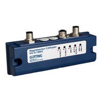
Magnet Sensor
Brand:
Gotting
| Category:
Accessories
| Size: 1 MB
Table of Contents
Table of Contents
3
1 About this Document
5
Function
5
Presentation of Information
5
Warning Notices
5
Symbols
6
Table 1 Hazard Classification According to ANSI Z535.6-2006
6
2 Introduction
7
Range of Use
7
Qualification of the Users
7
Intended Use
7
Functional Principle
9
Figure 1 Detection of the Magnetic Field
9
Figure 2 Three Detection Systems for the Recognition of Junctions
9
Figure 3 Signal Paths of the Outputs (Idealized Diagram)
10
Figure 4 Dependence of the Output on the Height above the Magnetic Tape
10
3 Mounting
11
Magnetic Tape
11
Magnetic Tape Types
11
Figure 5 Supported and Unsupported Magnetization of the Magnetic Tape
11
Table 2 Order Numbers Magnetic Tape
11
Magnetic Tape Installation
12
Magnet Sensor
12
Requirements
12
Figure 6 Areas Around Sensor and Tape that Need to be Free of Ferromagnetic Materials
12
Mounting on the Vehicle
13
Figure 7 Casing Dimensions and Mounting Drill Holes of the Magnet Sensor
13
Connection Cable (Assembled on One Side)
14
Figure 8 Possible Mounting Pos. for the Magnet Sensor When Using an Optional Distance Piece
14
Table 3 Accessories / Cable Extensions
14
4 Commissioning
15
Configuration of the Magnet Sensor
15
Figure 9 Commissioning: Menus of the Service Program
15
Table 4 Thresholds for Two Magnetic Tracks with Standard Magnetic Tapes
16
Compensation of Permanent Magnetic Interferences
17
Compensation of Static Magnetic Interferences
17
Figure 10 Commissioning: Compensation of Static Magnetic Interferences
17
Deleting the Compensation
18
Automatic Calibration of the Track Detection
18
Figure 11 Commissioning: Automatic Calibration
18
5 Hardware
20
Leds
20
Figure 12 Positions of the Leds
20
Table 5 Meaning of the Leds
20
Pin Assignment
21
Pwr/Usb
21
Figure 13 Positions of the Connectors
21
Table 6 Pin Assignment ST 1 5 Pin
21
Can1/Can2
22
Turning off from the Main Track
22
Figure 14 Layout of Turnoffs
22
Table 7 CAN Bus: Pin Assignments CAN1 & CAN2
22
6 Software
24
Switch-On Behavior
24
Connection to a PC Via the USB Interface
24
Figure 15 Connection Example: USB Connection with a PC
24
Terminal Program
25
Service Program
25
Main Menu
25
Figure 16 Main Menu
25
Status Output
26
Status Line
26
Table 8 Status Displays in the Main Menu
26
Table 9 Status Line in the Main Menu
26
1) CSV Output
27
Figure 17 Menu CSV Output
27
Figure 18 Example of a CSV Text Recording
27
2) Settings
28
Figure 19 CSV Recording Imported into a Spreadsheet Application
28
Figure 20 Menu Settings (Showing CAN STD, Canopen@ Has Specific Settings)
28
C) Calibration Settings
29
3) RAW Data Monitor
29
Figure 21 Menu Calibration Settings
29
Figure 22 Menu RAW Data Monitor
29
Firmware Update
30
Figure 23 Menu Firmware Update
30
Figure 24 Firmware Update - Choose File
30
Figure 25 Firmware Update - Start Update
31
Figure 26 Firmware Update - Leave DFU Mode
31
7 CAN Bus Interface
32
Receiving Box
32
Table 10 CAN: Structure of the CAN Receiving Box
32
Table 11 CAN: Structure of the Command Byte
32
Transmitter Box
33
Table 12 CAN: Structure of the CAN Transmitter Box
33
Table 13 CAN: Structure of the System Status Byte
33
8 Canopen® Interface
34
Description of the Process Data Objects (Pdos)
34
Transmission Objects
34
Table 14 Canopen®: Structure of the CAN Transmitter Box
34
Table 15 Canopen®: Structure of the System Status
34
Reception Object
35
Heartbeat
35
Description of the Service Data Objects (Sdos)
35
Table 16 Canopen®: Structure Reception Box
35
Table 17 Canopen®: Structure of a Command
35
Table 18 Canopen®: Heartbeat Device Mode
35
Object Directory
36
Communication Specific Entries
36
Table 19 Canopen®: SDO Error Codes
36
Table 20 Canopen®: Overview of the Object Dir., Communication Specific Entries in the Range 0X1000 to 0X1Fff
36
Standardized Device Profile Range
38
Canopen® Object Dictionary
38
Device Type
38
Error Register
38
COB-ID SYNC Message
38
Device Name
38
Table 21 Canopen®: Overview of the Object Dir., Stand. Device Profile Range from 0X6000
38
Table 22 Canopen®: Device Type
38
Table 23 Canopen®: Error Register
38
Table 24 Canopen®: COB-ID SYNC Message
38
Hardware Version
39
Software Version
39
Producer Heartbeat Time
39
Identity Object
39
Receive PDO Parameter
39
Table 26 Canopen®: Hardware Version
39
Table 27 Canopen®: Software Version
39
Table 28 Canopen®: Producer Heartbeat Time
39
Table 29 Canopen®: Identity Object
39
Table 30 Canopen®: Receive PDO Parameter
39
Mapping RPDO_1
40
Transmit PDO_1 Parameter
40
Mapping Txpdo_1
40
Table 31 Canopen®: Mapping RPDO_1
40
Table 32 Canopen®: Transmit PDO_1 Parameter
40
Table 33 Canopen®: Mapping Txpdo_1
40
Bit Digital Input (Transmitted in Txpdo 1)
41
Bit Analog Inputs (Transmitted in Txpdo 1)
41
Bit Life Counter (Transmitted in Txpdo 1)
41
Table 34 Canopen®: 8 Bit Digital Input (Transmitted in Txpdo 1)
41
Table 35 Canopen®: 16 Bit Analog Inputs (Transmitted in Txpdo 1)
41
Table 36 Canopen®: 32 Bit Analog Inputs (Transmitted in Txpdo 1)
41
Table 37 Canopen®: 8 Bit Life Counter (Transmitted in Txpdo 1)
41
9 Maintenance
42
10 Trouble Shooting
43
Error Codes
43
Table 38 Error Codes
43
11 Technical Data
44
Table 39 Technical Data
44
List of Figures - Chapter 12 45 List of Figures
45
12 List of Figures
45
13 List of Tables
46
14 Index
47
15 Copyright and Terms of Liability
49
Copyright
49
Exclusion of Liability
49
Trade Marks and Company Names
49
Advertisement
Advertisement
Related Products
Gotting HG G-19600ZA
Gotting HG G-19370ZA
Gotting HG G-19370-B
Gotting HG G-19380-B
Gotting HG G-19370
Gotting HG G-19380
Gotting HG G-19603
Gotting HG G-193 0-B Series
Gotting HG G-73350ZB
Gotting HG G-98820ZB
Gotting Categories
Antenna
GPS
Accessories
Marine Radio
Controller
More Gotting Manuals
Login
Sign In
OR
Sign in with Facebook
Sign in with Google
Upload manual
Upload from disk
Upload from URL