Advertisement
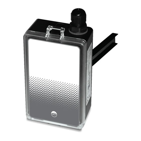
CARBON DIOXIDE DUCT SERIES
Installation & Operation Instructions
A/CO2-DUCT
GENERAL INFORMATION
The ACI Carbon Dioxide Duct Series (A/CO2-D)
monitors the carbon dioxide (CO2) levels in
industrial, commercial, school, and o ce-type
environments. The concentration of CO2 is a
strong indication of the overall indoor air
quality. The A/CO2 Series is based on a single
beam, non-dispersive infrared technology
and is a cost-e cient solution for measuring
carbon dioxide levels for building climate
control. In addition, ABC software eliminates
the need for manual calibration. Carbon
Dioxide concentration is measured up to
2,000 ppm and is converted into proportional
analog outputs. The factory default output is
4-20 mA, whereas 0-5 VDC and 0-10 VDC
outputs are eld selectable via integral dip
switches. The A/CO2-D provides data which
can be used in conjunction with a Building
Automation System or Demand Control
Ventilation to decrease energy consumption while creating a healthier indoor climate.
MOUNTING INSTRUCTIONS
Since there might be a substantial pressure di erence in duct mounting applications, it is essential to avoid
ambient air from suction into the duct mounting box. For correct function it is indispensable that the
sealing of the box cover, the cable entry bushings, the cable feed through and the duct entrance are
absolutely tight. The duct entrance may need extra sealing paste in order to prevent leakage. The PCB must
be handed carefully and protected from electrostatic discharge.
• Place the O-ring around the hole at the back of the box. See figure 2.
• Electrical cable entry: The box has a factory mounted cable entry bushing. Never feed more than one
cable through each cable entry bushing, or else gas might leak through!
• Mounting the tube: Drill a 1" (25 mm) diameter hole for the sampling probe and two holes with 0.16" (4
mm) diameter for the screws (5) into the air duct and mount the tube (1) with the gasket (2). The sampling
probe should be mounted with the largest locking knob on top. The unit can be mounted with the air
coming from the left or right.
• Attaching the sensor box is made to the sampling probe by a snap-in bayonet tting. Orient the box onto
the sampling probe so that the box upside is on the same side as the largest locking knob (3). When the
Automation Components, Inc.
2305 Pleasant View Road | Middleton, WI 53562
Phone: 1-888-967-5224 | Website: workaci.com
FIGURE 1: DIMENSIONS
3.31" (84mm)
5.98"
(151.89mm)
1.65"
(41.91mm)
Page 1
Phone: 1-888-967-5224
Website: workaci.com
5.59"
(142mm)
1.81"
(46mm)
8.03" (203.96mm)
Version: 4.0
I0000744
Advertisement
Table of Contents

Related Manuals for aci Carbon Dioxide Duct Series


Summary of Contents for aci Carbon Dioxide Duct Series
- Page 1 Installation & Operation Instructions Website: workaci.com A/CO2-DUCT FIGURE 1: DIMENSIONS GENERAL INFORMATION The ACI Carbon Dioxide Duct Series (A/CO2-D) 3.31” (84mm) monitors the carbon dioxide (CO2) levels in industrial, commercial, school, and o ce-type environments. The concentration of CO2 is a strong indication of the overall indoor air 5.59”...
- Page 2 Open the cover of the enclosure. ACI recommends 16 to 26 AWG twisted pair wires or shielded cable for all transmitters. Refer to FIGURE 3 for wiring diagrams. All wiring must comply with all local and National Electric Codes.
- Page 3 Note: When using a shielded cable, be sure to connect only (1) end of the shield to ground at the controller. Connecting both ends of the shield to ground may cause a ground loop. When removing the shield from the sensor end, make sure to properly trim the shield to prevent any chance of shorting. DIP SWITCH CONFIGURATION SW 1 sets the Output Signal.
- Page 4 ABC to work properly | If the building is occupied 24 hours / day, ABC must be turned o WARRANTY The A/CO2-DUCT Series is covered by ACI’s Five (5) Year Limited Warranty, which is located in the front of ACI’S SENSORS & TRANSMITTERS CATALOG or can be found on ACI’s website: www.workaci.com.
Need help?
Do you have a question about the Carbon Dioxide Duct Series and is the answer not in the manual?
Questions and answers