Sign In
Upload
Download
Table of Contents
Contents
Add to my manuals
Delete from my manuals
Share
URL of this page:
HTML Link:
Bookmark this page
Add
Manual will be automatically added to "My Manuals"
Print this page
×
Bookmark added
×
Added to my manuals
Manuals
Brands
Planet Manuals
Switch
XGS-6350-48X2Q4C
Quick installation manual
Planet XGS-6350-48X2Q4C Quick Installation Manual
Layer 3 48-port 10g sfp+ plus 4-port 100g qsfp28 managed switch
Hide thumbs
1
Table Of Contents
2
3
4
5
6
7
8
9
10
11
12
13
14
15
16
17
18
19
20
page
of
20
Go
/
20
Contents
Table of Contents
Bookmarks
Table of Contents
Table of Contents
1 Package Contents
2 Switch Management
3 Requirements
4 Terminal Setup
Logging on to the Console
Configuring Ip Address
Setting 1000Base-X For 10G Sfp+ Port
Setting 40Gbase-X For 100G Sfp+ Port
Changing Password
Saving The Configuration
5 Starting Web Management
Logging In To The Managed Switch From Management Port
Saving Configuration Via The Web
6 Led Indicators
Xgs-6350-24X4C
Xgs-6350-48X2Q4C
7 Customer Support
Advertisement
Quick Links
Download this manual
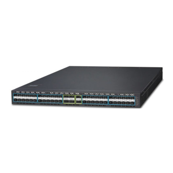
Layer 3 24-/48-Port 10G SFP+ plus 4-Port 100G
QSFP28 Managed Switch
XGS-6350-24X4C/XGS-6350-48X2Q4C
Quick Installation Guide
Table of
Contents
Previous
Page
Next
Page
1
2
3
4
5
Advertisement
Table of Contents
Need help?
Do you have a question about the XGS-6350-48X2Q4C and is the answer not in the manual?
Ask a question
Questions and answers
Related Manuals for Planet XGS-6350-48X2Q4C
Switch Planet XGSW-28040 Quick Installation Manual
24-port 10/100/1000mbps with 4 shared sfp plus 4-port 10g sfp plus managed switch (12 pages)
Switch Planet WGSD-10020 Command Manual
L2+ multi-port managed gigabit ethernet switch (433 pages)
Switch Planet XGS3-42000R User Manual
4-slot layer 3 ipv6/ ipv4 routing chassis switch (585 pages)
Switch Planet XGSW-28040HP User Manual
L2+ 24-port 10/100/1000mbps 802.3at poe + 4-port 10g sfp+ managed switch with hardware layer3 ipv4/ipv6 static routing (382 pages)
Switch Planet XGS3-24042 User Manual
24-port gigabit with 4 optional 10g slots layer 3 managed stackable switch (721 pages)
Switch Planet XGS3-24042 Quick Installation Manual
24-port gigabit with 4 optional 10g slots (16 pages)
Switch Planet XGS3-24242 Quick Installation Manual
Layer 3 24-port gigabit tp/sfp+4-port 10g sfp+ stackable managed switch (18 pages)
Switch Planet XGS-6350-12X8TR Quick Installation Manual
Layer 3 12-port 10g sfp+ + 8-port 10/100/1000t managed switch with dual 100~240v ac redundant power (17 pages)
Switch Planet XDL-2420R User Manual
24-port vdsl2 / adsl2+ ip dslam (111 pages)
Switch Planet XGS-6350-24X4C Quick Installation Manual
Layer 3 48-port 10g sfp+ plus 4-port 100g qsfp28 managed switch (20 pages)
Switch Planet XGS-5240-24X2QR Quick Installation Manual
Layer 2+ 24-port 10g sfp+ + 2-port 40g qsfp+ managed switch (16 pages)
Switch Planet XGS-6320-8X8TR Quick Installation Manual
L3 multi-port 10gigabit managed ethernet switch (16 pages)
Switch Planet XGS-6320-8UP4X Quick Installation Manual
L3 multi-port 10gigabit managed ethernet switch (16 pages)
Switch Planet XGS-6311 Series Quick Installation Manual
Layer 3 gigabit/10 gigabit managed ethernet switch (18 pages)
Switch Planet XGS-6311 Series Quick Installation Manual
Layer 3 gigabit/10 gigabit managed ethernet switch (15 pages)
Switch Planet XGPL-16000 Quick Installation Manual
16-port xgs-pon olt with 8-port 10g sfp+ + 2-port 100g qsfp28 (17 pages)
This manual is also suitable for:
Xgs-6350-24x4c
Table of Contents
Print
Rename the bookmark
Delete bookmark?
Delete from my manuals?
Login
Sign In
OR
Sign in with Facebook
Sign in with Google
Upload manual
Upload from disk
Upload from URL


Need help?
Do you have a question about the XGS-6350-48X2Q4C and is the answer not in the manual?
Questions and answers