
Related Manuals for Mitsubishi Electric PLK-G2010R


Summary of Contents for Mitsubishi Electric PLK-G2010R
- Page 1 INDUSTRIAL SEWING MACHINE MODEL PLK-G2010R TECHNICAL MANUAL SEWING MACHINE HEAD BASIC A180E598P02...
- Page 2 FOR SAFE USE Before the installation, operation, and inspection for this product, read the “FOR SAFE USE” and the technical manuals carefully. Also read the other technical manuals, “Control Unit” and “Operation Panel” describing some instructions, which are not in this manual, and use the sewing machine properly. SAFETY INDICATIONS Indicates that incorrect handling may cause hazardous conditions, resulting DANGER...
- Page 3 SAFETY PRECAUTIONS DANGER To prevent from receiving an electric shock, always turn off a power switch and unplug power supply when opening a control box, and then open after ten minutes passes. CAUTION USAGE ENVIRONMENT Please do not operate the sewing machine under the following conditions. (1) In the ambient temperature of 35 degrees (95°F) or more than 35 degrees, or the ambient temperature of 5 degrees or less than 5 degrees (41°F).
- Page 4 (9) Please make sure to fit the safety protective equipment (the motor cover or the others) and the accessory protective equipment (the eye guard) that removed temporarily for installation. (10) If the table and the steel stand are not MITSUBISHI original, the table and the steel stand have to be strong enough to withstand the weight and vibration of the sewing machine.
-
Page 5: Table Of Contents
CONTENTS 1. STRUCTURE OF THE SEWING MACHINE···································· 2. INSTALLATION········································································ 2-1. Preparation of the table·········································································· 2-2. Preparation of the steel stand·································································· 2-3. Installation of the control box··································································· 2-4. Installation of the operation panel····························································· 2-5. Installation of the power switch and foot switch············································ 2-6. -
Page 6: Structure Of The Sewing Machine
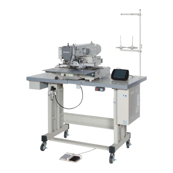
1. STRUCTURE OF THE SEWING MACHINE PLK-G2010R electronic pattern sewing machine consists of the following main parts. <10> <2> <1> <3> <5> <9> <8> <4> <11> <7> <6> <1>: Sewing machine head <2>: Main shaft motor <3>: Halt switch <4>: Control box <5>: Operation panel <6>: Work holder foot switch <7>: Start foot switch <8>:Gas spring... -
Page 7: Installation
2. INSTALLATION CAUTION (1) Please have some specialists, who have enough experience for the sewing machine installations, install the sewing machine. (2) Please have a qualified electrician perform necessary electric wiring. (3) Please do not operate until the sewing machine is repaired when any damage or fault is found on the sewing machine at the installation. -
Page 8: Preparation Of The Steel Stand
2-2. Preparation of the steel stand (1) If the steel stand is not MITSUBISHI original, please refer to the dimensions shown on the figure at the right. (2) When fitting the caster to the steel stand, the steel stand has to be strong enough to withstand the weight and vibration of the sewing machine. -
Page 9: Installation Of The Oil Pan
2-6. Installation of the oil pan (1) Remove the oil pan A (No.1) from the accessory box then, set the oil bottle (No.2) to the oil pan A (No.1). (2) Put the oil pan at the position shown on the figure then, fix the oil pan with staples (No.3). (3) Set the damper cushions (No.4) to the table. -
Page 10: Installation Of The Stays
<1>: Hinge shaft (two shafts) <3> <2>: Set screw (two screws) <3>: Hinge (two hinges) <8> <4>: Hinge rubber (two rubbers) <5>: Support plate (two plates) <6>: Socket bolt (four bolts) <7>: Flat washer (four washers) <8>: Head rest <9> <9>: Safety socket bolt (four bolts) <4>... -
Page 11: Installation Of The Tilting Detect Switch
2-9. Installation of the tilting detect switch (1) Install the switch unit (No.1) with the SW-MW screws (No.2) so that the switch turns on when the machine head in initial position is pushed by the machine table. NOTE The switch unit (No.1) is temporarily fixed at the back side of the sewing machine bed. -
Page 12: Connection Of The Electric Cables
2-11. Connection of the electric cables CAUTION (1) Please make sure to ground the place where there is a mark. Failure to do so may cause electric shock and/or malfunction. (1) Connect the machine head and the control box with cables as shown on the figure. (2) Hold the dangling cables under the table with accessory tie holders (MB60A0420) and cord ties (MB60A0201). -
Page 13: Installation Of The Thread Stand
2-12. Installation of the thread stand (1) Assemble the parts (No.1 to No.11) of the thread stand as shown on the figure. (2) Fit the thread stand into the hole at the far right on the table stand with the nut (No.13) and the washers (No.12). -
Page 14: Lubrication
3. LUBRICATION CAUTION (1) Please make sure to turn power switch off before lubricating. (2) Please pay attention that oil does not get on your skin or in your eyes as it may cause an inflammation. (3) Please make sure to keep oil out of the reach of children who may drink oil by mistake. [Notice] Please make sure to lubricate when operating for the first time after the installation. - Page 15 MEMO From the library of Superior Sewing Machine & Supply LLC - www.supsew.com...
- Page 16 Printed in Japan From the library of Superior Sewing Machine & Supply LLC - www.supsew.com...
Need help?
Do you have a question about the PLK-G2010R and is the answer not in the manual?
Questions and answers