Table of Contents
Advertisement
Quick Links
This manual serves the following
ComNet Model Numbers:
NW1/M
NW2/M
NWK1/M
NWK2/M
INSTALLATION AND OPERATION MANUAL
MINI INDUSTRIAL OUTDOOR 802.11A/N WIRELESS ETHERNET
Thank you for purchasing NetWave® from ComNet. This installation guide applies to
the following models:
NW1/M: Industrial Multipoint, FCC Version, User Configurable
NW2/M: Industrial Multipoint, ETSI Version, User Configurable
NWK1/M: Industrial Multipoint Kit, FCC Version (Includes NWK1/M_AP and
NWK1/M_CL)
NWK2/M: Industrial Multipoint Kit, ETSI Version (Includes NWK2/M_AP and
NWK2/M_CL)
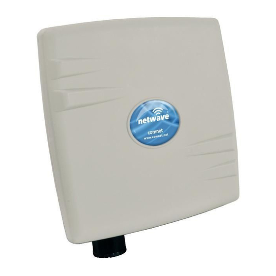
The NetWave industrially hardened wireless Ethernet transmission link from ComNet
can be configured through the embedded User Interface as a Client or as an Access
Point. This point-to-multipoint model allows multiple Ethernet endpoints to be
connected to a central Access Point. Up to 15 endpoints can be linked to a central
access point. The NW1/M and NW2/M support up to 95Mbps throughput using
MIMO technology. An easy to read LED array displays unit operational status along
with received signal strength ensuring optimal installation and operation. The units
are passive powered by PoE (Power over Ethernet) through a supplied PoE injection
module. The NW1/M is FCC certified and the NW2/M is ETSI, DFS and TPC certified.
Advertisement
Table of Contents

Related Manuals for Comnet NW2/M


Summary of Contents for Comnet NW2/M
- Page 1 MIMO technology. An easy to read LED array displays unit operational status along with received signal strength ensuring optimal installation and operation. The units are passive powered by PoE (Power over Ethernet) through a supplied PoE injection module. The NW1/M is FCC certified and the NW2/M is ETSI, DFS and TPC certified.
-
Page 2: About This Guide
» NW(1,2)/M Quick Start Guideº » NWK(1,2)/M Datasheet » NWK(1,2)/M Quick Start Guideº Website For information on ComNet’s entire product line, please visit the ComNet website at http://www.comnet.net Support For any questions or technical assistance, please contact your sales person (sales@comnet.net) or the customer service support center (techsupport@comnet.net) -
Page 3: Table Of Contents
3.0 Point-to-Point Topology Utilizing Dual Ports 4.0 Cabling Requirements 5.0 Hardware Installation 5.1 Outdoor Ethernet Gland Installation 5.2 NW1/M and NW2/M Indicating LED Details 5.3 Outdoor Standard Mounting Hardware 5.4 Outdoor Upgrade Mounting Hardware 6.0 Key Default Configurations 7.0 Quick Configuration Detailed Configuration 8.0 Getting Started... - Page 4 INSTALLATION AND OPERATION MANUAL NW(1,2)/M 9.8 Network 9.9 DHCP Leases 9.10 Link Status (for Station Mode) 9.11 Routes 9.12 Kernel Log 9.13 Real-time Graphs 10.0 System Tab 10.1 System Properties 10.2 Time Synchronization 10.3 Administration 10.4 Services 10.5 SNMP 10.6 Reset Button 10.7 Indicating LEDs 10.8 Backup/Flash Firmware 10.9 Reboot...
- Page 5 INSTALLATION AND OPERATION MANUAL NW(1,2)/M 13.0 Troubleshooting 13.1 Troubleshooting steps 13.2 Resetting to factory default 14.0 Glossary 15.0 Agency Compliance 16.0 GPL (General Public License) Statement TECH SUPPORT: 1.888.678.9427 INS_NW(1,2)/M_REV– 06/10/13 PAGE 5...
-
Page 6: Overview
Copyright © 2015 Communication Networks, LLC (dba ComNet). All rights reserved. Disclaimer ComNet reserves the right to make changes in specifications at any time without notice. The information furnished by ComNet in this material is believed to be accurate and reliable. However, ComNet assumes no responsibility for its use. -
Page 7: Introduction
Ethernet endpoints to be connected to a central Access Point. Up to 15 endpoints can be linked to a central access point. The NW1/M and NW2/M support up to 95Mbps throughput using MIMO technology. An easy to read LED array displays unit operational status along with received signal strength ensuring optimal installation and operation. -
Page 8: Point To Multi-Point
There is a MAC address lock feature that can be enabled through the user interface but is not enabled by default. The NW(1,2)/M includes a 16dBi 30° internal antenna and there is an optional 8dBi 70° internal antenna. See the ComNet website for the latest information regarding antenna support. Preconfigured NWK kits do not support point-to-multipoint topologies. -
Page 9: Cabling Requirements
Shielded CAT 5 or better should be used for all out of plant Ethernet connection and should be properly grounded through the PoE AC ground. Industrial grade shielded Ethernet cable is recommended to help prevent ESD damage commonly experienced with outdoor installations. www.comnet.net/comnet-products/cables Visit 5.0 Hardware Installation 5.1 Outdoor Ethernet Gland Installation... - Page 10 INSTALLATION AND OPERATION MANUAL NW(1,2)/M Connect one end of an RJ-45 Ethernet cable to the LAN OUT port of the Power Injection Module (PIM) and the other end to LAN of the access point – as sown below. Note: Maximum length of the RJ-45 CAT5 cable is 90 meters. Connect the RJ-45 Ethernet cable attached to the PIM to a network device, such as a switch or to the configuration PC.
-
Page 11: Nw1/M And Nw2/M Indicating Led Details
INSTALLATION AND OPERATION MANUAL NW(1,2)/M 5.2 NW1/M and NW2/M Indicating LED Details VISUAL CUE INDICATION SOLID GREEN Power is supplied to the unit POWER No power is supplied to the unit or the unit is in reset. SOLID GREEN LAN Connected... -
Page 12: Outdoor Upgrade Mounting Hardware
INSTALLATION AND OPERATION MANUAL NW(1,2)/M 6.0 Key Default Configurations IP Address of Web Server 192.168.10.100 (NWKX_AP) 192.168.10.101 for all others LAN Mode for Web Server Static Addressing Web Server User ID admin Web Server Password admin SSID NetWave-1 WPA Pre-shared Key 12345678 Channel-Frequency (AP) Auto... -
Page 13: Quick Configuration
• Select Apply Settings • Select Save Note: NW1/M and NW2/M Multipoint nodes will need to have the Wireless Mode set to either AP or Client (default is Client). And the IP addresses will need to be all set to different addresses (default address is 192.168.10.101). - Page 14 INSTALLATION AND OPERATION MANUAL NW(1,2)/M TECH SUPPORT: 1.888.678.9427 INS_NW(1,2)/M_REV– 06/10/13 PAGE 14...
-
Page 15: Detailed Configuration
INSTALLATION AND OPERATION MANUAL NW(1,2)/M Detailed Configuration 8.0 Getting Started To access the NetWave configuration interface, perform the following steps: 1. Connect the local area network (LAN) port of the router to the network port of your computer using an Ethernet cable. Ethernet cables are also known as LAN cables or network cables. They connect devices such as computers, routers, and switches on wired networks. -
Page 16: Operating Modes
INSTALLATION AND OPERATION MANUAL NW(1,2)/M 8.1 Operating Modes The Netwave Radio can operate in the following modes: 1. Access Point WDS 2. Station (Client) WDS In a commonly used setup, the WAN port of an access point connects to a modem via an Ethernet cable. - Page 17 INSTALLATION AND OPERATION MANUAL NW(1,2)/M 8.2.1 Reset Button The reset button is a physical hardware button on the board. Please refer to Section "Reset Button." 8.2.2 Indicating LEDs The light emitting diodes (LEDs) on the board are described in Section "LEDs on the Board". 8.2.3 Buzzer The new NetWave buzzer makes the following sounds: •...
-
Page 18: Status Tab
INSTALLATION AND OPERATION MANUAL NW(1,2)/M 9.0 Status Tab After login, when you click on the Status top-level tab, you can see the second-level tabs of Overview, Routes, System Log, Kernel Log, and Real-time Graphs. This is shown in Figure 2. Figure 2: The Status Tab. -
Page 19: Wireless
INSTALLATION AND OPERATION MANUAL NW(1,2)/M 9.2 Wireless The wireless chipset model is shown in the little box on the left e.g. AR9342 802.11an Radio. Figure 4: Wireless chipset model. The characters AP in the small callout box means that the radio is operating in the Access Point (AP) mode. -
Page 20: Wireless (For Station Mode)
INSTALLATION AND OPERATION MANUAL NW(1,2)/M 9.4 Wireless (for Station Mode) The following describes the parameters for a device operating in Station mode. Figure 6: A summary in the Wireless section for a device operating as an 802.11 station. SSID Displays the name of the wireless network that this station should be associated with. Mode This is 'Client' if the device is in Station WDS mode. -
Page 21: Associated Stations (For Ap Mode)
INSTALLATION AND OPERATION MANUAL NW(1,2)/M 9.5 Associated Stations (for AP Mode) This section shows the connected devices, if the Radio is in the AP mode. Figure 7: List of Associated Stations. If there are no associated stations, the text “No information available” is displayed. The parameters shown are as follows: MAC-Address Displays the MAC address of the station's radio. -
Page 22: Network
INSTALLATION AND OPERATION MANUAL NW(1,2)/M 9.8 Network This section displays the status of the LAN and WAN networks. Figure 10: Network summary. Status: Shows summaries of the interfaces for the LAN and WAN zones. This may include uptime, MAC address, protocol, bytes and packets received by the device, bytes and packets transmitted by the device, and its IPv4 address. -
Page 23: Routes
INSTALLATION AND OPERATION MANUAL NW(1,2)/M The box directly to its right shows a real-time graph of the TX-CCQ over the past 60 seconds. On the right of this section, there are 3 vertical bars. Each bar shows the current received signal strength of each antenna e.g. -
Page 24: Kernel Log
INSTALLATION AND OPERATION MANUAL NW(1,2)/M 9.12 Kernel Log This page shows the kernel debugging messages. This kernel log can also be obtained by typing “dmesg” in a serial console such as Tera Term if a suitable serial connector is used. Figure 14: The Status »... -
Page 25: Real-Time Graphs
INSTALLATION AND OPERATION MANUAL NW(1,2)/M 9.13 Real-time Graphs Under the tab for Real-time Graphs, there are four tabs titled Load, Traffic, Wireless, and Connection. 9.13.1 Load Figure 15: The graph for Real-time Load. TECH SUPPORT: 1.888.678.9427 INS_NW(1,2)/M_REV– 06/10/13 PAGE 25... - Page 26 INSTALLATION AND OPERATION MANUAL NW(1,2)/M 9.13.2 Traffic Figure 16: The graph for Real-time Traffic. 9.13.3 Wireless Figure 17: The graph for Real-time Wireless. TECH SUPPORT: 1.888.678.9427 INS_NW(1,2)/M_REV– 06/10/13 PAGE 26...
- Page 27 INSTALLATION AND OPERATION MANUAL NW(1,2)/M 9.13.4 Connection Figure 18: The graph for Real-time Connections. TECH SUPPORT: 1.888.678.9427 INS_NW(1,2)/M_REV– 06/10/13 PAGE 27...
-
Page 28: System Tab
INSTALLATION AND OPERATION MANUAL NW(1,2)/M 10.0 System Tab This section is about the System top-level tab. Under this tab, there is a row of tabs for Administration, Services, SNMP, LED Configuration, Backup/Flash Firmware, and Reboot. This can be seen in Figure 18. Figure 19: The System top-level tab. -
Page 29: Time Synchronization
INSTALLATION AND OPERATION MANUAL NW(1,2)/M Logging Figure 20: Changing the system properties for Logging. Logging Specifies parameters used for the system log, such as System log buffer size, External system log server, External system log server port, Log output level, and Cron Log Level. -
Page 30: Administration
INSTALLATION AND OPERATION MANUAL NW(1,2)/M 10.3 Administration Within the System » Administration page, you can configure the Router Password, SSH, Telnet, Web, and FTP settings. 10.3.1 Router Password Figure 23: Setting the router password. Password Allows you to set the Router password, the default being password. Confirmation Requires you to re-enter the password. - Page 31 INSTALLATION AND OPERATION MANUAL NW(1,2)/M 10.3.3 Telnet Figure 25: Telnet settings in the System » Administration page. Telnet Provides administrator tools for controlling the device or network debugging, over an unencrypted connection. Port Specifies the listening port, the default being 23. To start using Telnet, enter the command “telnet 192.168.10.101”...
-
Page 32: Services
INSTALLATION AND OPERATION MANUAL NW(1,2)/M 10.4 Services In the System» Services page, you can configure the Ping Watchdog and the Auto Reboot. 10.4.1 Ping Watchdog Figure 27: Ping Watchdog settings in the System » Services page. Ping Configures the device to ping to a remote IP address and reboot if the connection is Watchdog lost. -
Page 33: Snmp
INSTALLATION AND OPERATION MANUAL NW(1,2)/M 10.5 SNMP The Simple Network Management Protocol (SNMP) is an Internet-standard protocol for managing devices on IP networks. It consists of a set of standards for network management, including an application layer protocol, a database schema, and a set of data objects. SNMP exposes management data in the form of variables on the managed systems, which describe the system configuration. -
Page 34: Reset Button
INSTALLATION AND OPERATION MANUAL NW(1,2)/M SNMP V3 Privacy Password Sets the password for data encryption. (default: password) Trap Figure 30: SNMP trap configuration. Enable SNMP Trap Allows the SNMP agent to notify the SNMP manager of events. SNMP Trap IP Address Sets the IP address of the SNMP manager which receives the trap messages. -
Page 35: Indicating Leds
INSTALLATION AND OPERATION MANUAL NW(1,2)/M 10.7 Indicating LEDs 10.7.1 LED Configuration for Signal Strength Indicator LEDs #1 to #4 The System » LED Configuration page customizes how the LEDs indicate the received signal strength. Signal strength Chooses the Wireless interface, which is the wireless network name. indicator interface Signal strength Sets the received signal strength thresholds (in dBm) above which RSSI LEDs #1 to #4... -
Page 36: Backup/Flash Firmware
INSTALLATION AND OPERATION MANUAL NW(1,2)/M 10.8 Backup/Flash Firmware The System » Backup/Flash Firmware page lets you perform backup and restore, or flash a new firmware. 10.8.1 Backup/Restore Download backup Generate archive: Downloads a tar archive of the current configuration files. Note: The backup archive file should be stored in a safe place because it contains the wireless password in clear text. -
Page 37: Network Tab
INSTALLATION AND OPERATION MANUAL NW(1,2)/M 11.0 Network Tab You can view and configure the interfaces of the local area network (LAN) zone as well as the wide area network (WAN) zone. Network address translation (NAT) occurs between these two network zones. -
Page 38: Interfaces - Wan
INSTALLATION AND OPERATION MANUAL NW(1,2)/M 11.1 Interfaces – WAN The Network » Interfaces » WAN page configures the interface for the WAN zone. 11.1.1 Common Configuration General Setup Status Shows a summary of the interface for the WAN zone. This includes uptime, MAC address, bytes and packets received by the device, bytes and packets transmitted by the device, and its IPv4 address. - Page 39 INSTALLATION AND OPERATION MANUAL NW(1,2)/M Protocol – DHCP client The Dynamic Host Configuration Protocol (DHCP) is a standardized networking protocol used by servers on an IP network to allocate IP addresses automatically to client devices. Hostname to send Specifies the name of this device as seen by the remote DHCP server. when requesting DHCP Protocol –...
- Page 40 INSTALLATION AND OPERATION MANUAL NW(1,2)/M Protocol – L2TP The Layer 2 Tunneling Protocol (L2TP) is a tunneling protocol used to support virtual private networks (VPNs) or as part of the delivery of services by ISPs. It does not provide any encryption or confidentiality by itself.
-
Page 41: Interfaces - Lan
INSTALLATION AND OPERATION MANUAL NW(1,2)/M 11.2 Interfaces – LAN 11.2.1 Common Configuration General Setup Status Shows a summary of the current LAN port status, which includes uptime, MAC address, received bytes and packets, transmitted bytes and packets, and IPv4 address. Protocol Chooses between Static address, where you can specify the device IP address, or DHCP client, where the device obtains it IP address automatically. - Page 42 INSTALLATION AND OPERATION MANUAL NW(1,2)/M Advanced Settings The following are options in the Advanced Settings section tab. Some of these options are shown, depending on the protocol being used. Override Allows you to specify a different MAC address other than the Radio's original MAC MAC address address.
- Page 43 INSTALLATION AND OPERATION MANUAL NW(1,2)/M 11.2.2 DHCP Server This section allows you to configure the device as a DHCP server. General Setup Ignore Disables DHCP for this interface. You should uncheck this to enable DHCP. interface Note: All the following options in this DHCP Server section depend on DHCP being enabled. Start Specifies the lowest leased address as offset from the network address, the default being 100.
-
Page 44: Wifi - Overview
INSTALLATION AND OPERATION MANUAL NW(1,2)/M 11.3 WiFi – Overview Clicking on the Network » WiFi tab would bring you to the Wireless Overview page. This page shows the radios present on the device. These may include the on-board radio and the miniPCI/ miniPCIe radio card. - Page 45 INSTALLATION AND OPERATION MANUAL NW(1,2)/M 11.3.1 Radio in AP Mode When a radio is operating as an AP, the section for Associated Stations shows a list of stations connected to this device. Figure 37: The Associated Stations are also shown on the Wireless Overview page. The MAC address, network name, received signal strength, noise power, transmit rate, receive rate, and transmission quality for each station are displayed.
- Page 46 INSTALLATION AND OPERATION MANUAL NW(1,2)/M 11.3.2 Spectrum: Interference Analyzer For a radio in AP mode, clicking the Spectrum button would bring up the Channel Scan Report. Figure 38: The Channel Scan Report. The button 'Radio 1 View' shows the number of neighboring access points for each channel, the Min RSSI, Max RSSI, Noise Floor, and Channel Load.
- Page 47 INSTALLATION AND OPERATION MANUAL NW(1,2)/M 11.3.3 Radio in Station Mode A radio can operate as a Station. This can be set in the Interface Configuration » General Setup » Mode option, after clicking on the Edit button. Figure 39: The Wireless Overview page showing a radio as a Client (station). The following buttons are for a radio operating as a station.
-
Page 48: Wifi - Wireless Network
INSTALLATION AND OPERATION MANUAL NW(1,2)/M 11.4 WiFi – Wireless Network As mentioned earlier, clicking on the Edit button for a network would bring you to the configuration page. This page contains the sections Device Configuration and Interface Configuration. The Device Configuration section covers the physical settings of the radio hardware such as channel, transmit power, or antenna selection. - Page 49 INSTALLATION AND OPERATION MANUAL NW(1,2)/M Enable Enables the wireless network. Disable Disables the wireless network. Country Code Selects the country. Each country has its own transmit power and frequency regulations. To ensure regulatory compliance, you must select the country where the device is operating in.
- Page 50 INSTALLATION AND OPERATION MANUAL NW(1,2)/M Understanding the Maximum Transmit Power Calculation The maximum transmit power calculation is illustrated with the following examples. Example » Country Code: CZ, Channel = 100 » Antenna Gain is 5dBi » Transmit Power is 15dBm In the Czech Republic, Channel = 100 would mean the maximum power is 30dBm for EIRP.
- Page 51 INSTALLATION AND OPERATION MANUAL NW(1,2)/M Advanced Settings Figure 41: Advanced Settings for the Wifi Device Configuration. Distance Determines the distance of the connected station from the AP and automatically Optimization adjusts the ACK timeout. This is disabled by default. If the stations are positioned (Auto-ACK over a wide area at different distances from the AP, it is recommended to disable Timeout)
- Page 52 INSTALLATION AND OPERATION MANUAL NW(1,2)/M 11.4.2 Interface Configuration The Interface Configuration section contains the section tabs for General Setup, Wireless Security, MAC-Filter, and Advanced Settings. General Setup Figure 42: The Wifi Interface Configuration section. Mode Selects whether the device is operating as an Access Point WDS and Station WDS. Note: Setting more than 1 station on a board is not supported because there can only be one default gateway.
- Page 53 INSTALLATION AND OPERATION MANUAL NW(1,2)/M A Wireless Distribution System (WDS) is a system enabling the wireless interconnection of access points in an IEEE 802.11 network. It allows a wireless network to be expanded using multiple access points without the traditional requirement for a wired backbone to link them. The notable advantage of WDS over other solutions is it preserves the MAC addresses of client frames across links between access points.
- Page 54 INSTALLATION AND OPERATION MANUAL NW(1,2)/M WPA or WPA2 with EAP The Extensible Authentication Protocol (EAP) is encapsulated by the IEEE 802.1X authentication method. IEEE 802.1X is equivalent to EAP over LAN or WLAN. Enterprise networks commonly use this authentication method. WPA or WPA2 with EAP (AP Mode) Figure 44: Encryption options for WPA-EAP or WPA2-EAP in AP mode.
- Page 55 INSTALLATION AND OPERATION MANUAL NW(1,2)/M WPA or WPA2 with EAP (Station Mode) Figure 45: Encryption options for WPA-EAP or WPA2-EAP in Station mode. Cipher Only Cipher option is CCMP (AES) EAP-Method The authentication protocol can be set to Transport Layer Security (TLS), Tunneled TLS (TTLS), or Protected EAP (PEAP).
- Page 56 INSTALLATION AND OPERATION MANUAL NW(1,2)/M MAC-Filter This section tab is only available for a device operating as an AP. Figure 46: Configuring the MAC-Filter for a Wifi AP. MAC-Address Lets you allow only devices with the listed MAC address to associate with this AP, or lets Filter you block devices with the listed MAC address.
- Page 57 INSTALLATION AND OPERATION MANUAL NW(1,2)/M Advanced Settings Figure 47: Advanced Settings for the Wifi Interface. RTS Threshold Sets the threshold for the packet size above which the request to send (RTS) mechanism is used. The default is 2346 octets. There is a trade-off to consider when setting this parameter. On the one hand, using a small value causes RTS packets to be sent more often, consuming more of the available bandwidth, and therefore reducing the throughput of the network packet.
-
Page 58: Hostnames
INSTALLATION AND OPERATION MANUAL NW(1,2)/M 11.5 Hostnames In the Network » Hostnames page, you can specify custom hostnames (URLs) with their respective IP addresses. This is an additional local DNS. Note: The computers in the same subnet need to set the IP address of this device as their preferred DNS server in order to interpret these custom hostnames. -
Page 59: Firewall
INSTALLATION AND OPERATION MANUAL NW(1,2)/M 11.7 Firewall The Network » Firewall page contains the subpages for General Settings, Port Forwards, and Traffic Rules. 11.7.1 General Settings The firewall creates zones over the network interfaces to control network traffic flow. The Network » Firewall » General Settings page contains the zone settings. Zone Settings Figure 49: General Settings for the Firewall Zones. - Page 60 INSTALLATION AND OPERATION MANUAL NW(1,2)/M Figure 51: Adding a port forwarding rule. 11.7.3 Traffic Rules The Network » Firewall » Traffic Rules page configures the traffic rules and source NAT. Traffic Rules Traffic rules define policies for packets travelling between different zones, for example to reject traffic between certain hosts or to open WAN ports on the router.
-
Page 61: Diagnostics
INSTALLATION AND OPERATION MANUAL NW(1,2)/M Source NAT Source NAT is a specific form of masquerading which allows fine grained control over the source IP used for outgoing traffic, for example to map multiple WAN addresses to internal subnets. Figure 54: Source NAT. 11.8 Diagnostics 11.8.1 Network Utilities Figure 55: Network Utilities consist of Ping, Traceroute, and Nslookup. -
Page 62: Quality Of Service
INSTALLATION AND OPERATION MANUAL NW(1,2)/M 11.9 Quality of Service The Network » QoS page configures the quality of service (QoS). With QoS you can prioritize network traffic that passes through the WAN port. You can limit the download and upload speeds. Network QoS is disabled by default. -
Page 63: Ap Controller Tab
12.0 AP Controller Tab APs running the Netwave OpenWRT firmware can be managed by an Access Point Controller (APc). The APc sends and receives information from Comnet OpenWRT APs using the SNMPv3 protocol. 12.1 Getting Started with Managing APs using the APc For each AP, please perform the following steps in the AP's web page: 1. -
Page 64: Ipsec
INSTALLATION AND OPERATION MANUAL NW(1,2)/M 12.3 IPSec By default, the Internet Protocol Security (IPsec) is disabled for the Netwave Radio boards to decrease the usage of the CPU resources. It can also be enabled. The L2TPv3 itself already provides data channel protection against malicious data insertion. Pre-shared key Sets the password for the IPsec. - Page 65 INSTALLATION AND OPERATION MANUAL NW(1,2)/M 13.0 Troubleshooting 13.1 Troubleshooting steps 13.1.1 PC cannot connect to the router The configuration web page for the router would not be able to show up if the router and your computer are not connected. If the PC and the router are joined to the network by LAN cables, they would not be able to connect if any of the network cable connections are loose.
- Page 66 INSTALLATION AND OPERATION MANUAL NW(1,2)/M 14.0 Glossary Term Definition Access Point (AP) A device that provides network access to associated stations (connected wireless devices). A wireless router can function as an AP. Acknowledgment. This is a response to a transmission to indicate that the data packet was received correctly.
- Page 67 INSTALLATION AND OPERATION MANUAL NW(1,2)/M Term Definition Layer 2 Data link layer of the Open Systems Interconnection (OSI) model. This corresponds to the Link layer of the Internet protocol suite. MAC Address Media Access Control Address. This is a globally unique identifier attached to a network adapter.
- Page 68 INSTALLATION AND OPERATION MANUAL NW(1,2)/M Term Definition User Datagram Protocol. This is a protocol for transmitting data over the Internet quickly but with no guarantee of reliability or in-order delivery. Virtual Access Point. A VAP simulates a physical access point. A VAP is configured on a per-radio basis.
- Page 69 INSTALLATION AND OPERATION MANUAL NW(1,2)/M 15.0 Agency Compliance Changes or modifications not expressly approved by the party responsible for compliance could void the user’s authority to operate the equipment. This device complies with Part 15 of the FCC Rules. Operation is subject to the following two conditions: •...
- Page 70 INSTALLATION AND OPERATION MANUAL NW(1,2)/M RF Exposure Warning The antennas used for this transmitter must be installed to provide a separation distance of at least 2.52m from all persons and must not be located or operating in conjunction with any other antenna or transmitter.
- Page 71 The Licenses allow you to freely copy, modify and redistribute that software without any other statement or documentation from us. ComNet will provide to anyone who contacts us at the contact provided below, for a charge of no more than our cost of physically performing source code distribution, a complete machine- readable copy of the complete corresponding source code for the free software programs used in the version of the programs that we distribute to you.
- Page 72 8 TURNBERRY PARK ROAD | GILDERSOME | MORLEY | LEEDS, UK LS27 7LE T: +44 (0)113 307 6400 | F: +44 (0)113 253 7462 | INFO-EUROPE@COMNET.NET © 2015 Communications Networks Corporation. All Rights Reserved. “ComNet” and the “ComNet Logo” are registered trademarks of Communication Networks, LLC. TECH SUPPORT: 1.888.678.9427...
Need help?
Do you have a question about the NW2/M and is the answer not in the manual?
Questions and answers