Advertisement

VG2440V
Display
User Guide
IMPORTANT: Please read this User Guide to obtain important information on installing and using your product in
a safe manner, as well as registering your product for future service. Warranty information contained in this User
Guide will describe your limited coverage from ViewSonic® Corporation, which is also found on our web site at
http://www.viewsonic.com in English, or in specific languages using the Regional selection box in the upper right
corner of our website. "Antes de operar su equipo lea cu idadosamente las instrucciones en este manual"
Model No. VS18402
P/N: VG2440V

Advertisement

Table of Contents
loading

Summary of Contents for ViewSonic VS18402

  • Page 1 Warranty information contained in this User Guide will describe your limited coverage from ViewSonic® Corporation, which is also found on our web site at http://www.viewsonic.com in English, or in specific languages using the Regional selection box in the upper right corner of our website.
  • Page 2 At ViewSonic®, we believe that our products have the potential to make a positive impact in the world, and we are confident that the ViewSonic® product you have chosen will serve you well.
  • Page 3: Safety Precautions

    • Do not place any heavy objects on the device or connection cables. • If smoke, an abnormal noise, or a strange odor is present, immediately turn the device off and call your dealer or ViewSonic®. It is dangerous to continue using the device.
  • Page 4 • When connecting to a power outlet, DO NOT remove the grounding prong. Please ensure grounding prongs are NEVER REMOVED. • Protect the power cord from being treaded upon or pinched, particularly at the plug, and at the point where it emerges from the equipment.
  • Page 5: Table Of Contents

    Contents Safety Precautions ............3 Introduction ..............7 Package Contents ....................7 Product Overview ....................8 Initial Setup ..............9 Installing the Stand ....................9 Wall Mounting ......................12 Using the Security Slot ..................14 Making Connections ..........15 Connecting to Power ....................15 Connecting External Devices ................16 HDMI Connection ....................
  • Page 6 Appendix ..............46 Specifications ......................46 Glossary ........................49 Troubleshooting ....................54 Maintenance......................56 General Precautions ....................56 Cleaning the Screen ....................56 Cleaning the Case ....................56 Disclaimer ......................56 Product Upgradeability and Repairability ............57 Regulatory and Service Information ......58 Compliance Information ..................58 FCC Compliance Statement ...................
  • Page 7: Introduction

    Introduction Package Contents • IPS display • Power cord • Video cable • USB cable • Quick start guide NOTE: The power cord and video cables included in your package may vary depending on your country. Please contact your local reseller for more information.
  • Page 8: Product Overview

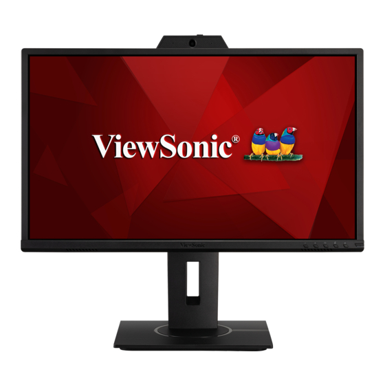
    Product Overview Front View Webcam Display screen Power button NOTE: For more information about the 1 (Volume Down) / 2 (Volume Up) / 3 (Speaker Mute) / 4 (Microphone Mute) / 5 (OSD Menu) key and its functions, refer to “Hot Keys” on page 29. Rear View USB Downstream Security Slot...
  • Page 9: Initial Setup

    Initial Setup This section provides detailed instructions for setting up your monitor. NOTE: The monitor comes packaged in a user-friendly box to make installation easy. Installing the Stand 1. Place the box on a flat, stable surface and open the front flap of the box to reveal the contents.
  • Page 10 4. Align and slide the upper hooks of the monitor stand into the stand mounting slots as shown in the illustration below: NOTE: Ensure the stand is secure and the quick release tab positively clicks into place.
  • Page 11 5. Using the stand’s handle, lift the device out of the box and into its upright position on a flat, stable surface. NOTE: Always place the device on a flat, stable surface. Failure to do so may cause the device to fall and damage the device and/or result in personal injury.
  • Page 12: Wall Mounting

    Refer to the table below for the standard dimensions for wall mount kits. NOTE: For use only with a UL Listed Wall Mount Bracket. To obtain a wall- mounting kit or height adjustment base, contact ViewSonic® or your local dealer.
  • Page 13 5. Attach the mounting bracket to the VESA mounting holes at the rear of the device. Then secure it with four (4) screws (M4 x 10 mm). 100 mm 6. Follow the instructions that come with the wall mounting kit to mount the monitor onto the wall.
  • Page 14: Using The Security Slot

    Using the Security Slot To help prevent the device from being stolen, use a security slot locking device to secure the device to a fixed object. Additionally, fastening the monitor to a wall or fixed object using a security cable can help support the weight of the monitor in order to prevent the monitor from falling over.
  • Page 15: Making Connections

    Making Connections This section guides you on how to connect the monitor with other equipment. Connecting to Power 1. Connect the power cord to the AC IN jack at the rear of the device. 2. Connect the power cord plug to a power outlet.
  • Page 16: Connecting External Devices

    Connecting External Devices HDMI Connection Connect one end of an HDMI cable to the HDMI port of your monitor. Then connect the other end of the cable to the HDMI port of your computer. NOTE: The monitor is equipped with one HDMI 1.4 port.
  • Page 17: Displayport Connection

    DisplayPort Connection Connect one end of a DisplayPort cable to the DisplayPort port. Then connect the other end of the cable to the DisplayPort or mini DP port of your computer. NOTE: To connect the monitor to the Thunderbolt port (v. 1&2) on your Mac, connect the mini DP end of the “mini DP to DisplayPort cable”...
  • Page 18: Vga Connection

    VGA Connection Connect one end of a VGA cable to the VGA port of your monitor. Then connect the other end of the cable to the VGA port of your computer.
  • Page 19: Usb Connection

    USB Connection Connect one end of a USB cable to a USB port of the monitor. Then connect the other end of the cable to a USB port of your computer. NOTE: The monitor supports two (2) types of USB ports. When making the connection(s), observe the following guidelines: •...
  • Page 20: Audio Connection

    Audio Connection Plug the audio jack of the ear-/headphones into the Audio Out port of the monitor. Additionally, you can connect the monitor to a sound bar using an audio cable. NOTE: The monitor is also equipped with dual speakers.
  • Page 21: Using The Monitor

    Using the Monitor Adjusting the Viewing Angle For optimal viewing, you can adjust the viewing angle using any of the following methods: Height Adjustment Lower or raise the monitor to the desired height (0 to 130 mm). NOTE: When adjusting, press down firmly along the adjustment track.
  • Page 22: Tilt Angle Adjustment

    Tilt Angle Adjustment Tilt the monitor forwards or backwards to the desired viewing angle (-5° to 40°). NOTE: • When adjusting, support the stand firmly with one hand while tilting the monitor forwards or backwards with the other hand. • The monitor must be lifted to the highest position, then it can support 40° tilt.
  • Page 23 2. Rotate the monitor 90° clockwise or counter clockwise from landscape to portrait orientation. NOTE: • To rotate the screen image, manually change the system’s display orientation settings. • When adjusting, make sure to hold both sides of your monitor firmly with both hands.
  • Page 24: Swivel Angle Adjustment

    Swivel Angle Adjustment Swivel the monitor to the left or right for the desired viewing angle (60°).
  • Page 25: Turning The Device On/Off

    Turning the Device On/Off 1. Plug the power cord into a power outlet. 2. Press the Power button to turn on the monitor. 3. To turn the monitor off, press the Power button again. NOTE: The monitor will still consume some power as long as the power cord is connected to the power outlet.
  • Page 26: Using The Webcam

    Using the Webcam NOTE: To activate the webcam, ensure the monitor is connected to your computer via the USB Upstream port. Uncovering and Covering the Webcam Uncovered Covered...
  • Page 27: Tilting The Webcam

    Tilting the Webcam Tilt the slider door forwards or backwards to adjust the viewing angle (-5° to 5°).
  • Page 28: Using The Control Panel Keys

    Using the Control Panel Keys Use the control panel keys to adjust the volume, mute the speaker, mute the microphone, and navigate the On-Screen Display (OSD) Menu. 1 3 5 Quick Menu Volume Down/Volume Up Press the 1 or 2 key to adjust the speaker volume. Speaker Mute Press the 3 key to mute/unmute the speaker.
  • Page 29: Hot Keys

    Hot Keys When the On-Screen Display (OSD) Menu is off, you can quickly access special functions by using the control panel keys. Description 2 + 3 Press and hold the keys to lock/unlock the OSD Menu. When the menu appears on the screen, continue holding both keys for 10 seconds to lock/unlock the OSD Menu.
  • Page 30 Description 2 + 4 Press and hold the keys to lock/unlock the Power button. When the menu appears on the screen, continue holding both keys for 10 seconds to lock/unlock the Power button. Power Lock/Unlock Locking Power Button Press and hold for 10s to lock power If the Power button is locked, the below message will appear on the screen:...
  • Page 31: Configuring The Settings

    Configuring the Settings General Operations 1920 X 1080 @ 60Hz 1920 X 1080 @ 60Hz Key Guide 1. Press the 5 key to display the OSD Menu. ViewMode Color Adjust Manual Image Input Audio/Mic Setup Menu Select Adjust D-Sub HDMI DisplayPort 1920 X 1080 @ 60Hz 2.
  • Page 32 3. Press the 1 or 2 key to select the desired menu option. Then press the 3 key to enter the sub-menu. Manual Image Input Audio/Mic ViewMode Color Adjust Setup Menu Select Adjust Volume Speaker Mute Microphone Mute 1920 X 1080 @ 60Hz 4.
  • Page 33 NOTE: Certain menu option adjustments do not require the user to press the 3 key to confirm the selection. Follow the key guide that appears on the bottom of the screen to select the option or make adjustments. Input Audio/Mic ViewMode Color Adjust Manual Image...
  • Page 34: On-Screen Display (Osd) Menu Tree

    On-Screen Display (OSD) Menu Tree Main Menu Sub-menu Menu Option Input Select D-Sub (VGA) HDMI DisplayPort Audio/Mic Volume (-/+, 0~100) Speaker Mute Microphone Mute ViewMode Office Text CUSTOM 1/2/3 Low Input Lag On/Off Black (-/+, 0/10/20/30/40/50/60/ Stabilization 70/80/90/100) Advanced DCR (-/+, 0/25/50/75/100) Response Time Standard...
  • Page 35 Main Menu Sub-menu Menu Option ViewMode Game FPS 1 FPS 2 MOBA Color Adjust Contrast/ Contrast (-/+, 0~100) Brightness Brightness (-/+, 0~100) Color sRGB Temperature Bluish Cool Native Warm User Color (-/+, 0~100) Green (-/+, 0~100) Blue (-/+, 0~100) Color Space¹ Auto Color Range¹...
  • Page 36 Main Menu Sub-menu Menu Option Setup Menu Language English Français Deutsch Español Italiano Suomi Русский Türkçe 日本語 한국어 繁體中文 简体中文 Česká Svenska Resolution Notice Information OSD Timeout (-/+, 5/15/30/60) OSD Background On OSD Pivot 0˚ +90˚ -90˚ Power Indicator Auto Power Off Sleep 30 Minutes 45 Minutes...
  • Page 37 Main Menu Sub-menu Menu Option Setup Menu DisplayPort 1.2³ DDC/CI Auto Detect All Recall ¹ If a D-Sub connection is detected, it will be grayed out. ² If no D-Sub connection is detected, it will be grayed out. ³ If no DisplayPort connection is detected, it will be grayed out.
  • Page 38: Menu Options

    Menu Options Input Select 1. Press the 5 key to display the OSD Menu. 2. Press the 1 or 2 key to select Input Select. Then press the 3 key to enter the Input Select menu. Input Audio/Mic ViewMode Color Adjust Manual Image Setup Menu Select...
  • Page 39 Audio/Mic 1. Press the 5 key to display the OSD Menu. 2. Press the 1 or 2 key to select Audio/Mic. Then press the 3 key to enter the Audio/Mic menu. Input Audio/Mic ViewMode Color Adjust Manual Image Setup Menu Select Adjust Volume...
  • Page 40 ViewMode Menu 1. Press the 5 key to display the OSD Menu. 2. Press the 1 or 2 key to select ViewMode. Then press the 3 key to enter the ViewMode menu. Manual Image Input Audio/Mic ViewMode Color Adjust Setup Menu Select Adjust Office...
  • Page 41 Color Adjust Menu NOTE: Some sub-menus may not be adjustable depending on the user’s custom settings. 1. Press the 5 key to display the OSD Menu. 2. Press the 1 or 2 key to select Color Adjust. Then press the 3 key to enter the Color Adjust menu.
  • Page 42 Menu Option Description Color Temperature Select the color temperature setting. • sRGB: Precise color gamut and gamma of the sRGB standard. • Bluish: Set the color temperature to 9300K. • Cool: Set the color temperature to 7500K • Native: Default color temperature. Recommended for regular use.
  • Page 43 Manual Image Adjust Menu 1. Press the 5 key to display the OSD Menu. 2. Press the 1 or 2 key to select Manual Image Adjust. Then press the 3 key to enter the Manual Image Adjust menu. Input Audio/Mic ViewMode Color Adjust Manual Image...
  • Page 44 Setup Menu 1. Press the 5 key to display the OSD Menu. 2. Press the 1 or 2 key to select Setup Menu. Then press the 3 key to enter the Setup Menu menu. Manual Image Input Audio/Mic ViewMode Color Adjust Setup Menu Select Adjust...
  • Page 45 Menu Option Description Language Select an available language for the OSD Menu. Enable this option to allow the system to inform users that Resolution Notice the current viewing resolution is not the correct native resolution. Information Display the monitor information. Set the length of time the OSD Menu remains on the OSD Timeout screen.
  • Page 46: Appendix

    Appendix Specifications Item Category Specifications Type IPS, a-Si TFT active matrix 1920 x 1080 LCD 0.2745 (H)mm x 0.2745 (V)mm pixel pitch Display Size 60.5 cm (23.8” viewable) Color Filter RGB vertical stripe Glass Surface Anti-Glare type, 3H hard coating, Haze 25 Input Signal Video Sync Separate Sync...
  • Page 47 Item Category Specifications Resolution Supported • 1920 x 1080 @ 50, 60Hz • 1680 x 1050 @ 60Hz • 1600 x 1200 @ 60Hz • 1600 x 900 @ 60Hz • 1440 x 900 @ 60, 75Hz • 1440 x 576 @ 50Hz •...
  • Page 48 Do not set the graphics card in your computer to exceed these timing modes; doing so may result in permanent damage to the display. ² Please use the power adapter from ViewSonic® or an authorized source only. ³ Maximum power consumption without Audio or USB.
  • Page 49: Glossary

    Auto Image Adjust Automatically adjusts the screen image for an ideal viewing experience. Black Stabilization ViewSonic’s Black stabilization provides heightened visibility and detail by brightening dark scenes. Blue Light Filter Adjusts the filter that blocks high-energy blue light for a more comfortable viewing experience.
  • Page 50 Color Range The monitor can detect the input signal color range automatically. You can manually change the color range options to fit the correct color range if the colors are not displayed correctly. Options Description The monitor automatically recognizes the color format Auto and black and white levels.
  • Page 51 Displays the timing mode (video signal input) coming from the graphics card in the computer, the LCD model number, the serial number, and the ViewSonic® website URL. See your graphics card’s user guide for instructions on changing the resolution and refresh rate (vertical frequency).
  • Page 52 Manual Image Adjust Displays the “Manual Image Adjust” menu. You can manually set a variety of image quality adjustments. Memory Recall Returns the adjustments back to factory settings if the display is operating in a factory preset timing mode listed in the “Specifications” of this manual. NOTE: •...
  • Page 53 Sharpness Adjusts the picture quality of the monitor. ViewMode ViewSonic®’s unique ViewMode feature offers “Game,” “Movie,” “Web,” “Text,” and “Mono” presets. These presets are specifically designed to deliver an optimized viewing experience for different screen applications. YUV Color Space YUV color space is used for color image and video processing;...
  • Page 54: Troubleshooting

    • Connect the monitor to another computer. • If you have an older graphics card, contact ViewSonic® for a non-DDC adapter. Screen image is too • Adjust the brightness and contrast settings. light or dark •...
  • Page 55 Problem or Issue Possible Solutions The screen is not • Adjust the resolution to the correct Aspect Ratio. centered correctly • Adjust the horizontal and vertical controls via the OSD Menu. • Reset the monitor to factory settings. The screen appears •...
  • Page 56: Maintenance

    • ViewSonic® does not recommend the use of any ammonia or alcohol-based cleaners on the display screen or case. Some chemical cleaners have been reported to damage the screen and/or case of the monitor. • ViewSonic® will not be liable for damage resulting from use of any ammonia or alcohol-based cleaners.
  • Page 57: Product Upgradeability And Repairability

    Product Upgradeability and Repairability The following is a list of hardware features available Upgradable Repairable Replaceable for at least 5 years after the sale of the product. Main Processor(s) or SOC Memory Wireless Networking Capability Graphics Card Rechargeable Battery Fan Assembly Camera Fingerprint Reader Display Assembly...
  • Page 58: Regulatory And Service Information

    Regulatory and Service Information Compliance Information This section addresses all connected requirements and statements regarding regulations. Confirmed corresponding applications shall refer to nameplate labels and relevant markings on the unit. FCC Compliance Statement This device complies with part 15 of FCC Rules. Operation is subject to the following two conditions: (1) this device may not cause harmful interference, and (2) this device must accept any interference received, including interference that may cause undesired operation.
  • Page 59: Declaration Of Rohs2 Compliance

    The following information is only for EU-member states: The mark shown to the right is in compliance with the Waste Electrical and Electronic Equipment Directive 2012/19/EU (WEEE). The mark indicates the requirement NOT to dispose of the equipment as unsorted municipal waste, but use the return and collection systems according to local law.
  • Page 60: Indian Restriction Of Hazardous Substances

    Schedule 2 of the Rule. Product Disposal at End of Product Life ViewSonic® respects the environment and is committed to working and living green. Thank you for being part of Smarter, Greener Computing. Please visit the ViewSonic®...
  • Page 61: Tco Information

    TCO Information A third-party certi cation according to ISO 14024 Toward sustainable IT products Say hello to a more sustainable product IT products are associated with a wide range of sustainability risks throughout their life cycle. Human rights violations are common in the factories.
  • Page 62: Copyright Information

    ENERGY STAR® is a registered trademark of the U.S. Environmental Protection Agency (EPA). As an ENERGY STAR® partner, ViewSonic® Corporation has determined that this product meets the ENERGY STAR® guidelines for energy efficiency. Disclaimer: ViewSonic® Corporation shall not be liable for technical or editorial errors or omissions contained herein;...
  • Page 63: Customer Service

    For technical support or product service, see the table below or contact your reseller. NOTE: You will need the product’s serial number. Country/ Region Website Country/ Region Website Asia Pacific & Africa Australia www.viewsonic.com/au/ Bangladesh www.viewsonic.com/bd/ www.viewsonic.com.cn www.viewsonic.com/hk/ 中国 (China) 香港 (繁體中文) Hong Kong (English) www.viewsonic.com/hk-en/ India www.viewsonic.com/in/...
  • Page 64: Limited Warranty

    How long the warranty is effective: ViewSonic® displays are warranted for between 1 and 3 years, depending on your country of purchase, for all parts including the light source and for all labor from the date of the first consumer purchase.
  • Page 65 (e) the serial number of the product. • Take or ship the product, freight prepaid, in the original container to an authorized ViewSonic® service center or ViewSonic®. • For additional information or the name of the nearest ViewSonic® service center, contact ViewSonic®. Limitation of implied warranties:...
  • Page 66 Exclusion of damages: ViewSonic’s liability is limited to the cost of repair or replacement of the product. ViewSonic® shall not be liable for: • Damage to other property caused by any defects in the product, damages based upon inconvenience, loss of use of the product, loss of time, loss of...
  • Page 67: Mexico Limited Warranty

    If a product proves to be defective in material or workmanship during the warranty period, ViewSonic® will, at its sole option, repair or replace the product with a like product. Replacement product or parts may include remanufactured or refurbished parts or components &...
  • Page 68 Exclusion of damages: ViewSonic®’s liability is limited to the cost of repair or replacement of the product. ViewSonic® shall not be liable for: • Damage to other property caused by any defects in the product, damages...
  • Page 69 Name, address, of manufacturer and importers: México, Av. de la Palma #8 Piso 2 Despacho 203, Corporativo Interpalmas, Col. San Fernando Huixquilucan, Estado de México Tel: (55) 3605-1099 http://www.viewsonic.com/la/soporte/index.htm NÚMERO GRATIS DE ASISTENCIA TÉCNICA PARA TODO MÉXICO: 001.866.823.2004 Hermosillo: Villahermosa: Distribuciones y Servicios Computacionales SA de CV.
  • Page 70 C0 M91 Y72 K24 Process Color C0 M0 Y0 K100 Process Color C0 M91 Y72 K24 Process Color Pantone Black C Spot Color Pantone 187 C Spot Color...

This manual is also suitable for:

Vg2440v

Table of Contents