Table of Contents
Advertisement
Quick Links
Advertisement
Table of Contents

Related Manuals for Leonton EG5-0501-SFP Series


Summary of Contents for Leonton EG5-0501-SFP Series
- Page 1 Leonton EG5-0501-SFP Series (EG5-0501-SFP / EG5-0501-SFP-T) User Manual...
- Page 2 Disclaimer Leonton Technologies, Co. Ltd. provides this manual without warranty of any kind, expressed or implied, including but not limited to the implied warranties of merchantability and fitness for a particular purpose.
- Page 3 This is a Class-A product. In a domestic environment this product may cause radio interference in which case the user may be required to take adequate measures. This document is the current official release manual. Please check our website (www.leonton.com) for any updated manual or contact us by e-mail (sales@leonton.com).
-
Page 4: Table Of Contents
Contents Overview ........................1 Software Features ....................1 Hardware Features ....................2 Package Contents ....................2 Safety Precaution ....................3 Hardware Description ....................4 Physical Dimensions ....................4 Front Panel ......................5 Top View ....................... 5 LED Indicators......................6 Ethernet Ports ....................... 7 Cabling ........................ -
Page 5: Overview
Overview This series is rated IP30 and installation by DIN Rail. Each unit of this industrial gigabit managed Ethernet switch series has 4* 10/100/1000TX Gigabit Ethernet ports and 1 dual-rate (100/1000) SFP slots, suitable for applications that require high bandwidth and long distance communication. In order to prevent unregulated voltage, this series provides high EFT and ESD protection. -
Page 6: Hardware Features
TFTP, Web GUI, CLI USB Port Configuration Backup/Restore Hardware Features Interface & Performance All Copper ports support auto MDI/MDI-X function Embedded 4*10/100/1000Tx and 1*100/1000 SFP Slot Store-and-forward switching architecture 8K MAC Address Table Supports 9.6Kbytes Jumbo Frame ... -
Page 7: Safety Precaution
Safety Precaution Attention If the DC voltage is supplied by an external circuit, please use a protection device on the power supply input. The industrial Ethernet switch’s hardware specs, ports, cabling information, and wiring installation will be described within this user manual. Warning Labels The caution label means that you should check the certain information on user manual when working with the device. -
Page 8: Hardware Description
Hardware Description Physical Dimensions Figure 2.1, below, shows the physical dimensions of EG5-0501-SFP series. (W x D x H) is 54mm x 99mm x 142mm Figure 2.1: EG5-0501-SFP Series Physical Dimensions... -
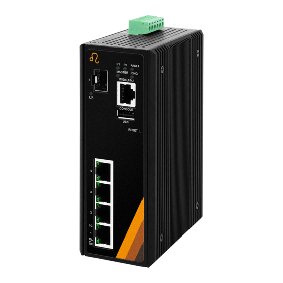
Page 9: Front Panel
Figure 2.2: The Front Panel of EG5-0501-SFP Series Top View Figure 2.3, below, shows the top panel of the EG5-0501-SFP series switch that is equipped with one 6-pin removal terminal block connector for dual DC power inputs (12~48VDC). Figure 2.3: Top Panel View of EG5-0501-SFP Series... -
Page 10: Led Indicators
Green Connected to network, 100Mbps/10Mbps 10/100 Flashing Networking is active (LAN Port 1-4) Not connected to network Table 2.4: LED Indictors for EG5-0501-SFP Series Caution: "P" is the abbreviation for "Power", "L" is for "Link", and "A" is for "Activity". -
Page 11: Ethernet Ports
Ethernet Ports RJ-45 Ports(Auto MDI/MDIX) The RJ-45 ports are auto-sensing for 10Base-T, 100Base-TX or 1000Base-T devices connections. Auto MDI/MDIX means that the switch can connect to another switch or workstation without changing the straight-through or crossover cabling. See the figures as below for straight-through and crossover cabling schematics. -
Page 12: Cabling
Cabling Use the four twisted-pair, category 5e, or the above cabling for RJ-45 port connections. The cable between the switch and the link partner (switch, hub, workstation, etc.) must be less than 100 meters (328 ft.) long. The small form-factor pluggable (SFP) is a compact optical transceiver used in optical communications for both telecommunication and data communication applications. - Page 13 Step 2 Insert the fiber cable of the LC connector into the transceiver as shown below in Figure 2.9. Figure 2.9: LC Connector to the Transceiver To remove the LC connector from the transceiver, please follow the steps shown below: Step 1 Press the upper side of the LC connector from the transceiver and pull it out to release as shown below in Figure 2.4 Figure 2.4: Remove LC Connector...
-
Page 14: Wiring The Power Inputs
Step 2 Push down the metal clasp and pull the transceiver out by the plastic part as shown below in Figure 2.5 Figure 2.5: Pull Out from the SFP Module Wiring the Power Inputs Caution: Please follow the below steps to insert the power wire. Step 1 Insert the positive and negative wires into the PWR1 (V1+, V1-) and PWR2 (V2+, V2-) contacts on the terminal block connector as shown below in Figure 2.6. -
Page 15: Grounding Note
Step 2 Tighten the wire-clamp screws to prevent the wires from loosening, as shown below in Figure 2.7. Figure 2.7: Power Terminal Block Caution: Only use copper conductors, 100°C, tighten to 5 in-lbs. The wire gauge for the terminal block should range between 18~20 AWG. Grounding Note Grounding and wire routing help limit the effects of noise due to electromagnetic interference (EMI). - Page 16 Figure 2.15: Wiring the Fault Alarm Contact Caution: The wire gauge for the terminal block should range between 12 ~ 24 AWG. If only using one power source, jumper Pin 1 to Pin 5 and Pin 2 to Pin 6 to eliminate power fault alarm.
-
Page 17: Mounting Installation
Mounting Installation DIN-Rail Mounting The DIN-Rail is pre-installed on the industrial Ethernet switch from the factory. If the DIN-Rail is not on the industrial Ethernet switch, please see Figure 3.1 to learn how to install the DIN-Rail on the switch. Figure 3.1: The Rear Side of the Switch and DIN-Rail Bracket Follow the steps below to learn how to hang the industrial Ethernet switch. - Page 18 Figure 3.2: Insert the Switch on the DIN-Rail Step 4 Lightly pull down the bracket on to the rail as shown below in Figure 3.3. Figure 3.3: Stable the Switch on DIN-Rail Step 5 Check if the bracket is mounted tightly on the rail. Step 6 To remove the industrial Ethernet switch from the rail, do the opposite from the above steps.
-
Page 19: Wall Mounting
Wall Mounting Follow the steps below to mount the industrial Ethernet switch using the wall mounting bracket as shown below in Figure 3.4. Caution: “Wall” means industrial control panel wall. Step 1 Remove the DIN-Rail bracket from the industrial Ethernet switch by loosening the screws. -
Page 20: Hardware Installation
Hardware Installation Installation Steps This section will explain how to install EG5-0501-SFP series. Caution: This device is intended for use indoor and at altitudes up to 2000 meters. Caution: The device is intended to be installed in an industrial control enclosure and panel. -
Page 21: Maintenance And Service
Maintenance and Service If the device requires servicing of any kind, the user is required to disconnect and remove it from its mounting. The initial installation should be done in a way that makes this as convenient as possible. ... -
Page 22: Trouble Shooting
Check for loose power connections, power losses or surges at the power outlet. Please contact Leonton for technical support service, if the problem still cannot be resolved. If the industrial switch LED indicators are normal and the connected cables are correct but the packets still cannot transmit, please check the system’s Ethernet devices’...
Need help?
Do you have a question about the EG5-0501-SFP Series and is the answer not in the manual?
Questions and answers