Table of Contents
Advertisement
Quick Links
Advertisement
Table of Contents

Subscribe to Our Youtube Channel
Related Manuals for Beko HLV-350


Summary of Contents for Beko HLV-350
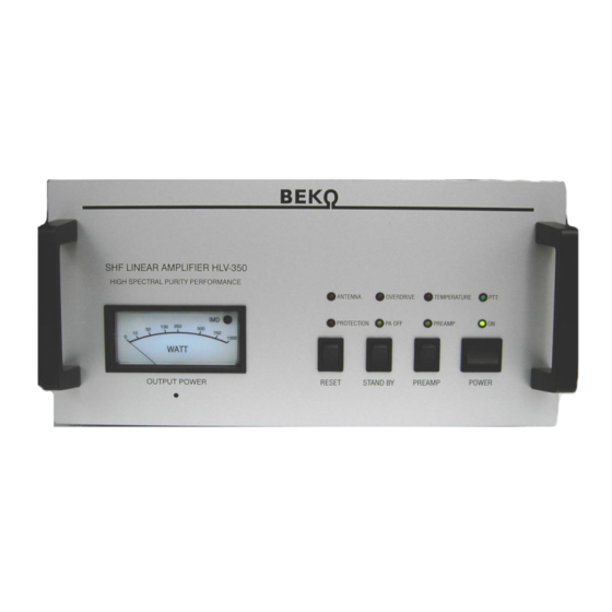
- Page 1 HLV-350 Instruction & Operations Manual...
-
Page 2: Table Of Contents
Content Chapter page Certificate of conformity Introduction Safety instructions Electrical connections Warranty Front panel operation Protection circuits Receive-Transmit switching Remote control Cooling technique Block diagram Adjustment of protection thresholds Control circuit schematic... -
Page 3: Certificate Of Conformity
1. CERTIFICATE OF CONFORMITY Hereby we declare that the following products: Linear amplifier HLV-250, HLV-350, HLV-400, HLV-550, HLV-800, HLV- 950, HLV-1000, HLV-1100, HLV-1950 and HLV-2000 fully meet all technical specifications according to EU directives as: 06/95/EC, 2004/108/EC and 99/5/EC: EN 301 783-1 V1.1.1 (2000-09), EN 301 783-2 V1.1.1 (2000-09 EN 301 489-1 V1.6.1 (2005-09), EN 301 489-15 V1.2.1 (2002-08) -
Page 4: Introduction
The HLV-350 is a solid state LDMOSFET SHF-amplifier covering the 1275 – 1300 MHz frequency range with a selectable gain of 17 db. The internal modulated power limit is kept to 500 watts. -
Page 5: Safety Instructions
3. Safety instructions Please be aware of the following before use: Caution! This device is generating high frequency energy with high power which is highly dangerous in case of improper connection and use. Mains connection is only allowed to sockets including a rules compliant PE connection. -
Page 6: Electrical Connections
4. Electrical connections In order to guarantee trouble free operation you should observe the following instructions: 1. The device is only permitted for operation with mains voltages of 100 – 260 Volts AC and frequencies between 50 - 60 Hz. 2. -
Page 7: Warranty
5. Warranty Congratulations for purchasing a BEKO power amplifier. This solid state device uses the latest circuit design techniques and features high quality “Made in Germany” precision assembly. This unit meets the latest CE conformity and FCC rules. We grant a 2 years warranty including parts and labour beginning from the date of purchase. -
Page 8: Front Panel Operation
“ON”-LED. It takes approx. 5 seconds until the internal supply voltage rises up to 50 VDC and releases PTT operation. The HLV-350 has an integrated pfc- controlled switched power supply with an efficiency of > 96%. The total mains power consumption @ 400 watts into a 50 ohms load is <900 watts. -
Page 9: Protection Circuits
RESET The HLV-350 operation is internally monitored by many highly efficient protection circuits. If any limit is exceeded the device shuts off. If any protection circuit is activated the red “PROTECTION”-LED illuminates as well as one of the three protection circuit LEDs “ANTENNA”, “OVERDRIVE”... -
Page 10: Receive-Transmit Switching
8. Transmit operation The RX/TX-switching is activated by applying zero volts or ground to the “PTT” or pin 6 of the “CONTROL”-jack on the rear panel. This will be indicated by the illuminated green “PTT”-LED. On most transceivers, a ground on transmit will be supplied separately by an accessory output on their rear panel. -
Page 11: Remote Control
100% of output power is equal to 10V DC on Pin 5. Use the 7-pin DIN plug that was delivered with your amplifier and connect the other end to a suitable connector to your transceiver or other switching unit. Remote control HLV-350 100% power level = 10V DC +15V DC... -
Page 12: Cooling Technique
10. Cooling technique The integrated axial blowers are temperature controlled and provide sufficient cooling during long time operation at full output power with minimum noise level. During the TX period the airflow through the RF box is increased by higher speed of the cavity blower which is noticeable by a slight noise increase. Especially during long term operation with MS or WSJT this is essential for avoiding rapid temperature rise of the RF pc board and the capacitors. -
Page 13: Block Diagram
11. Block diagram... -
Page 14: Adjustment Of Protection Thresholds
12. Adjustment of protection thresholds In some cases the default adjustments are too sensitive and need some slight correction. In the picture below all trimpots incl. their functions are shown. Turning the slots clockwise is equal to + or upward direction and verse vice. Readjustment should be done very carefully otherwise the effect of protection is cancelled. -
Page 15: Control Circuit Schematic
HLV-2000 2500 2000 1500 1000 12,5 17,5 22,5 27,5 32,5 Input power [W]...
Need help?
Do you have a question about the HLV-350 and is the answer not in the manual?
Questions and answers