Advertisement
Quick Links
Please read all instructional literature carefully and thoroughly before starting. Refer to the final page for the listing of Recommended
Practices, Liabilities and Warranties.
GENERAL
BEFORE INSTALLING, CHECK THE SENSOR MODEL SELECTED FOR
COMPATIBILITY TO THE PROCESS MEDIA IN CONTACT WITH THE
SENSOR AND WETTED PARTS.
The J21K Differential Pressure Switch utilizes opposing metal bellows to detect
pressure differences between two pressure sources. When the pressure at the
high port exceeds the pressure at the low port by a pre-determined amount
(set point), the mechanism operates a single snap-action electrical switch.
Control set point may be adjusted by turning the internal adjustment hex screw
(see Part II - Adjustments).
DIFFERENTIAL PROOF PRESSURE* LIMITS STATED IN THE LITERA
TURE AND ON NAMEPLATE MUST NEVER BE EXCEEDED, EVEN BY
SURGES IN THE SYSTEM. OCCASIONAL OPERATION OF UNIT UP TO
DIFFERENTIAL PROOF PRESSURE IS ACCEPTABLE (E.G., START-UP,
TESTING). CONTINUOUS OPERATION SHOULD NOT EXCEED THE
DESIGNATED MAX WORKING PRESSURE.**
*Differential Proof Pressure
The maximum differential pressure to which a pressure sensor may be
occasionally subjected, which causes no permanent damage (e.g., start-up,
testing). The unit may require calibration.
**Working Pressure
The pressure range within which two opposing sensors can be safely
operated and still maintain set point adjustability.
THESE PRODUCTS DO NOT HAVE ANY FIELD REPLACEABLE PARTS.
Please refer to product bulletin for product specifications. Product bulletin
may be found at www.ueonline.com.
Part I - Installation
MOUNTING
INSTALL UNIT WHERE SHOCK, VIBRATION AND TEMPERATURE
FLUCTUATIONS ARE MINIMAL. MOUNT UNIT SO THAT MOISTURE
IS PREVENTED FROM ENTERING THE ENCLOSURE. DO NOT MOUNT
UNIT IN AMBIENT TEMPERATURES EXCEEDING PUBLISHED LIMITS.
Surface mount in any position via two mounting ears. Never turn this unit by
grasping enclosure. Always hold a wrench on the bellows housing (or fitting)
when connecting pressure joints.
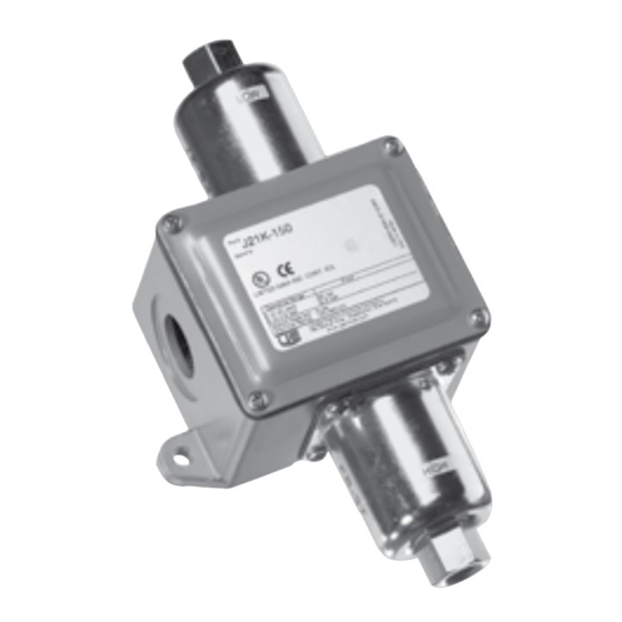
Type J21K
Differential Pressure Switch
Tools Needed
- Adjustable wrenches (2)
- Phillips head screwdrive
www.ueonline.com
U N I T E D E L E C T R I C
C O N T R O L S
Installation and Maintenance
Instructions
WIRING
DISCONNECT ALL SUPPLY CIRCUITS BEFORE WIRING UNIT. WIRE
UNITS ACCORDING TO NATIONAL AND LOCAL ELECTRICAL CODES.
MAXIMUM RECOMMENDED WIRE SIZE IS 14 AWG.
ELECTRICAL RATINGS STATED IN LITERATURE AND ON NAMEPLATES
MUST NOT BE EXCEEDED; OVERLOAD ON A SWITCH CAN CAUSE
FAILURE ON THE FIRST CYCLE.
Remove the four (4) screws retaining the cover and gasket. Remove cover.
Connect conduit to the enclosure using a conduit fitting that is suitable for your
installation. A watertight conduit fitting (option M900 or equivalent) must be
used for NEMA 4 protection. Wire directly to the switch terminals in accordance
with local and national electrical codes. Bring the wires up to the terminals
from the rear of the enclosure to prevent interference with the mechanism.
Part II - Adjustments
For set point adjustment and re-calibration, connect the "High" pressure port
to a calibrated pressure source.
Set point adjustment is achieved by varying the gap between the mechanical
actuator and the plunger on the electrical switch
To raise the differential pressure setting, turn the 5/16" hex head screw left
(clockwise).
To lower the differential pressure setting, turn the 5/16" hex head screw right
(counter-clockwise).
Types with Optional Adjustable Deadband Switch (Option
1520)
J21K models with option code 1520 incorporate a snap switch with integral
adjustment wheel. Turning this wheel raises or lowers the pressure rise set
point. The fall set point remains constant. To use the adjustable deadband
switch:
1.
Determine set point and deadband values. For example, a rising set
point of 20 psid with a deadband value of 6 psid.
r
2.
Set the falling set point at desired deadband value (determined by
subtracting the deadband value from the desired set point) using the
standard adjustment screw as outlined above. Using the example from
step 1, 20 - 6 = 14, so you would set the fall set point at 14 psid. This
is your constant.
3.
Set your deadband by turning the adjustment wheel left to raise or right
to lower the set point. Using the example from step 1, turn the wheel left
or right until 20 psid is achieved. This is your set point.
Consult UE for additional information.
IMJ21K-08
IMJ21K-08
Tools Needed
- 5/16" open end wrench
Advertisement

Related Manuals for United Electric Controls J21K


Summary of Contents for United Electric Controls J21K
- Page 1 Please refer to product bulletin for product specifications. Product bulletin 1520) may be found at www.ueonline.com. J21K models with option code 1520 incorporate a snap switch with integral adjustment wheel. Turning this wheel raises or lowers the pressure rise set Part I - Installation point.
- Page 2 RECOMMENDED PRACTICES AND WARNINGS Dimensions United Electric Controls Company recommends careful consideration of the Dimensional drawings for all models may be found at www.ueonline.com following factors when specifying and installing UE pressure and temperature units. Before installing a unit, the Installation and Maintenance instructions provided with unit must be read and understood.