Table of Contents
Advertisement
Quick Links
Advertisement
Table of Contents
Troubleshooting

Related Manuals for WELDTECH Workshop Series


Summary of Contents for WELDTECH Workshop Series
- Page 1 WT205MIG 200A INVERTER MIG WELDER OPERATING INSTRUCTIONS www.weldtech.net.nz...
-
Page 2: Welcome To Euroquip
Designed for discerning operators who seek professional results and product quality without the price tag of a full professional setup. Design emphasis is placed on simple, functional design and operation. Weldtech product is subject to stringent quality control and designed and manufactured to NZ & Australian standards. -
Page 3: Table Of Contents
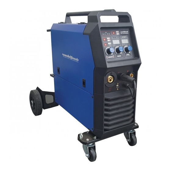
WT205MIG Welding Machine Contents Welcome to Euroquip..........2 Know Your Machine..........5 Controls Explained..........5 Tips & Tricks..............6 Quick Start Guide............7 Basic Operation............7 Accessories..............10 Care & Maintenance..........11 Welding Settings..........12 MIG Basic Welding Guide........13 MIG Welding Troubleshooting....17 MMA (Stick) Basic Welding Guide....19 MMA (Stick) Troubleshooting.......25 Knowledge & Resources........26 Safety .................26 Warranty..............31 www.weldtech.net.nz... - Page 4 WT205MIG 200A - INVERTER MIG WELDER Powerful - Welds from thin panel steel up to 10mmm Portable - Heavy duty integrated trolley with lifting points Digital Microprocessor Control System - Superior and dynamic arc characteristics • IGBT Inverter Technology • Heavy duty integrated trolley with lifting points • 4 Roll metal wire feed unit • Digital microprocessor control system • Spool gun connection...
-
Page 5: Know Your Machine
This effect can also be used to fine tune Inductance setting will have no effect on MIG spray the arc to produce less splatter. Wire speed, wire size transfer process (as opposed to short circuit) or MMA and type, shielding gas will all change the effect that welding process. www.weldtech.net.nz... -
Page 6: Tips & Tricks
2T/4T MIG Trigger Mode Button (3) Tips & Tricks 2T mode the trigger is pulled and held on to activate MIG Voltage & Wire Speed Settings the welding circuit, when the trigger is released, the welding circuit stops. 4T is known as ’latching’ mode. Voltage is essentially the power in the welding arc The trigger is pulled once and released to activate that sets the heat. -
Page 7: Quick Start Guide
Insufficient brake tension will cause the spool to Before changing the feed roller or wire spool, ensure ‘freewheel’ and the welding wire will unravel from that the mains power is switched off. the spool (known as a ‘birds nest’) www.weldtech.net.nz... - Page 8 5. Gas MIG Welding Operation WARNING! The use of excessive feed tension will cause rapid NOTE: Gas MIG welding will require a gas cylinder. and premature wear of the drive roller, the support bearing and the drive motor/ gearbox. 5.1 Connect the earth cable quick connector to the 3.1 Connect the MIG Torch Euro Connector to the MIG negative welding power output socket (13). Con- torch Euro connection socket (15) on the front of...
- Page 9 6.2 Connect the MIG power connection lead (12) to the positive welding power output socket (11). Note if this connection is not made, there will be no electrical connection to the welding torch! 6.3 Connect the spool gun Euro Connector to the MIG torch Euro connection socket (15) on the front of the machine. Secure by firmly hand tightening the threaded collar on the MIG Torch connector clock- wise. Connect the spool gun interface plug to the www.weldtech.net.nz...
-
Page 11: Accessories
• Check all cables before use. Common • Check electrode holders, work lead/ Spare Part #: Description: Consumables/ Parts clamps and welding torches before Accessories use. √ 13323 Weldtech Light Duty Spool Gun 4m √ 16895 15m H/D 15A Extension Lead (3x2.5mm2 wiring) • Replace worn electrode holders and √ DW1500 Auto Darkening Helmet, Fixed Shade earth clamps, which do not provide a √ DW3000 Auto Darkening Helmet, Shade 9-13 good connection. -
Page 12: Welding Settings
Welding Settings... -
Page 13: Mig Basic Welding Guide
Direction of Travel the process may be applied automatically or by ma- chine. Transverse Angle It is commonly used to weld large diameter elec- trodes in the flat and horizontal position and small www.weldtech.net.nz... - Page 14 FCAW Process (Fig 1-5) (Fig 1-2) Shielding Gas Nozzle (Optional) to 15 (Optional) Longitudinal Angle Molten Metal to 60 Transverse Molten Flux Cored Angle Slag Slag Electrode Direction Solidified Base of Travel Weld Metal Metal Gas Metal ARC Welding (GMAW). Position of MIG Torch (Fig 1-3) This process, also known as MIG welding, CO2 weld- ing, Micro Wire Welding, short arc welding, dip trans- fer welding, wire welding etc., is an electric arc weld-...
- Page 15 The longitudinal angle is the ables in short-arc welding of 24gauge (0.024”, 0.6mm) angle between the centre line of the welding gun to ¼” (6.4mm) mild sheet or plate. The applied tech- and a line perpendicular to the axis of the weld. The niques and end results in the GMAW process are con- longitudinal angle is generally called the Nozzle trolled by these variables. Angle and can be either trailing (pulling) or leading www.weldtech.net.nz...
- Page 16 (pushing). Whether the operator is left handed or right handed has to be considered to realize the The welding current is determined by the Current effects of each angle in relation to the direction of (Wire Speed) control, the current will increase with travel.
-
Page 17: Mig Welding Troubleshooting
GMAW, Porosity and Inconsistent wire feed. WARNING! Disengage the feed roll when testing for gas flow by ear. Wire feeding problems can be reduced by checking the following points. www.weldtech.net.nz... - Page 18 Other weld problems can be reduced by checking the following points.
-
Page 19: Mma (Stick) Basic Welding Guide
Overhead Position, Fillet Weld weld or skip welding to distribute the heat. (Fig 1-18) Cast Iron Most types of cast iron, except white iron, are weld- able. White iron, because of its extreme brittleness, www.weldtech.net.nz... - Page 20 generally cracks when attempts are made to weld it. tions without any special preparation. For heavier Trouble may also be experienced when welding sections and for repair work on castings, etc., it will white-heart malleable, due to the porosity caused by be necessary to cut or grind an angle between the gas held in this type of iron.
- Page 21 This freezing-on of the tip may be overcome by scratching the electrode along the plate surface in the same way as a match is struck. As soon as the arc is established, maintain a 1.6mm to 3.2mm gap between the burning electrode end and www.weldtech.net.nz...
- Page 22 Making Welded Joints the parent metal. Draw the electrode slowly along as it melts down. Having attained some skill in the handling of an elec- trode, you will be ready to go on to make up welded Another difficulty you may meet is the tendency, af- joints. ter the arc is struck, to withdraw the electrode so far that the arc is broken again.
- Page 23 Figure metal tends to sag towards the base, and undercut 1-26 illustrates multi-run technique and Figure 1-27 forms on the vertical leg. Multi-runs can be made as shows the effects of pausing at the edge of weave shown in Figure 1-24. Weaving in HV fillet welds is and of weaving too rapidly. undesirable. www.weldtech.net.nz...
- Page 24 waste pipe. Then tack this to the work bench or hold Examples of Vertical Fillet Welds in a vice so that the specimen is positioned in the (Fig 1-27) overhead position as shown in the sketch. CORRECT INCORRECT The electrode is held at 45º to the horizontal and tilted 10º in the line of travel (Figure 1-28). The tip of the electrode may be touched lightly on the metal, Pause at edge of weave...
-
Page 25: Mma (Stick) Troubleshooting
WT205MIG Welding Machine MMA (Stick) Troubleshooting www.weldtech.net.nz... -
Page 26: Knowledge & Resources
Knowledge & GENERAL SAFETY WARNINGS 1. Maintain labels and nameplates on the welder. Resources These carry important information. If unreadable or missing, contact Euroquip for a replacement. Please refer to Euroquip website www.euroquip.co.nz/ Downloads.html 2. Avoid unintentional starting. Make sure the for knowledgebase articles &... - Page 27 AS/NZS 1337.1 and AS/NZS 1338.1 Safety Stand- Unapproved safety equipment may not provide ards) to protect your face and eyes when weld- adequate protection. Eye and breathing protec- ing or watching. (See Filter Table on Page17). tion must be AS/NZS compliant for the specific 2. Wear approved safety glasses. Side shields are hazards in the work area. recommended. www.weldtech.net.nz...
- Page 28 3. Use protective screens or barriers to protect adequate ventilation in work areas to prevent ac- others from flash and glare; warn others not to cumulation of flammable gases, vapours, and dust. watch the arc. 7. Do not apply heat to a container that has held 4.
- Page 29 1. Keep your head out of the fumes. Do not breathe WARNING! the fumes. Welding produces fumes and gases. Breathing 2. If inside, ventilate the area and/or use an exhaust these fumes and gases can be hazardous to your at the arc to remove welding fumes and gases. health. www.weldtech.net.nz...
- Page 30 3. If ventilation is poor, use an approved air-sup- 8. Connect the work lead/clamp to the job as close to the welding area as practical to prevent weld- plied respirator. ing current from travelling long, possibly un- 4. Read the Safety Data Sheets (SDS) and the man- known paths and causing electric shock and fire ufacturer’s instruction for the metals, consuma- hazards.
-
Page 31: Warranty
Failure caused by incorrect operation of the product, lack of proper care and maintenance of the product, external damage, external circumstances such as contaminated fuel or poor water supply, modifica- tions to the product, attempted repair/ service by a Scan here to register your product www.weldtech.net.nz... - Page 32 Congratulations on your new WELDTECH product. We are proud to have you as our customer and will strive to provide you with the best service and reliability in the industry. This product is backed by our extensive service network. To locate your nearest distributor or service agency visit www.
Need help?
Do you have a question about the Workshop Series and is the answer not in the manual?
Questions and answers