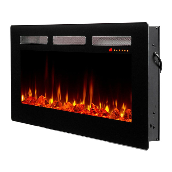
Dimplex SIL48 Service Manual
Hide thumbs
Also See for SIL48:
- Owner's manual (24 pages) ,
- Owner's manual (72 pages) ,
- Owner's manual (24 pages)
Table of Contents
Advertisement
Quick Links
Service Manual
IMPORTANT SAFETY INFORMATION:
Read this manual first before attempting to install or use this electric fireplace. Always comply with the
warnings and safety instructions contained in this manual to prevent personal injury or property damage.
7401090000R00
Models
SIL48/SIL48M
SIL60/SIL60M
SIL72
SIL96
Advertisement
Table of Contents

Related Manuals for Dimplex SIL48


Summary of Contents for Dimplex SIL48
- Page 1 Models SIL48/SIL48M SIL60/SIL60M SIL72 SIL96 Service Manual IMPORTANT SAFETY INFORMATION: Read this manual first before attempting to install or use this electric fireplace. Always comply with the warnings and safety instructions contained in this manual to prevent personal injury or property damage.
-
Page 2: Table Of Contents
SIL48......... -
Page 3: Exploded Parts Diagrams
8. Temperature Sensor (NTC) SIL48 MOD 0 ....9602330100RP SIL48 & SIL48M ....9602110800RP SIL48 MOD A . -
Page 4: Wiring Diagrams
Wiring Diagrams SIL48 Ember Bed Lights Flame Flicker Motor IR Receiver Thermistor Thermal Cutout Touch Pad Fuse L (Hot) Ground N (Neutral) SIL48M Ember Bed Lights Flame Flicker Motor IR Receiver Thermistor Thermal Cutout Touch Pad Fuse Heat Toggle Switch... -
Page 5: Sil60
Wiring Diagrams SIL60 Ember Bed Lights SIL72 Flame Flicker Motor Touch Pad Thermistor IR Receiver Thermal Cutout Fuse L (Hot) Ground N (Neutral) SIL96 Ember Bed Lights Flame Flicker Motor Touch Pad Thermistor IR Receiver Thermal Cutout Fuse L (Hot) Ground N (Neutral) -
Page 6: Replacement Part Procedures
Put the back panel aside (Figure 3). 7. Remove the 2 screws on each side of the top panel. Unplug the connector from the main control board, and put the top panel aside (Figure 4). Figure 2 Figure 1 Figure 4 Figure 3 www.dimplex.com... -
Page 7: Heater Assembly Replacement
Heater Assembly Replacement Tools Required: Phillips Head Screwdriver Side Cutters Pliers 1. Follow the steps of “Preparing for Service” on page 6 of this manual before continuing. 2. Using pliers, disconnect the wires from the main control board, making note of their original locations. 3. -
Page 8: Touch Pad Replacement
11. Secure the flame panel retaining bracket. 12. Reassemble the fireplace by reinstalling the top panel, followed by the back panel. Figure 7 Flame Panel Retaining Bracket Flame Panel Remove these screws Remove these screws (on both sides) www.dimplex.com... -
Page 9: Flicker Motor Replacement
Flicker Motor Replacement Tools Required: Phillips Head Screwdriver Wire Cutter/Stripper 1. Follow steps 1-6 of “Preparing for Service” on page 6 of this manual before continuing. 2. Remove the flicker rod by first taking it out from the middle brackets, then pulling it from the side opposite the flicker motor, and finally pulling it away from the flicker motor (Figure 8). -
Page 10: Heater Assembly Replacement
Use the provided zip ties to secure them out of the way of other components. 7. Reassemble the fireplace by reinstalling the top panel, followed by the back panel. Figure 11 www.dimplex.com... -
Page 11: Flame Led Replacement
Flame LED Replacement Tools Required: Phillips Head Screwdriver 1. Follow steps 1-6 of “Preparing for Service” on page 6 of this manual before continuing. 2. Remove the screws that secure the flame LED strip to the firebox. 3. Unplug the connectors from the LED strips on the left. 4. -
Page 12: Troubleshooting
Replace flicker motor Revision Date 1-888-346-7539 | www.dimplex.com 18-Oct-19 In keeping with our policy of continuous 23-Aug-21 product improvement, we reserve the right to make changes without notice. © 2021 Glen Dimplex Americas A BRAND OF GLEN DIMPLEX AMERICAS www.dimplex.com...
Need help?
Do you have a question about the SIL48 and is the answer not in the manual?
Questions and answers