axing RF MK 800 Operation Instructions Manual
Multituner dvb-c/dvb-t compact headend
Hide thumbs
Also See for RF MK 800:
- Operation instructions manual (132 pages) ,
- Operation instructions manual (45 pages) ,
- Operation instructions manual (152 pages)

Related Manuals for axing RF MK 800


Summary of Contents for axing RF MK 800
- Page 1 MK 800 | MK 1600 MK 806 | MK 1606 Multituner | DVB-C/DVB-T compact headend Operation instructions...
-
Page 2: Table Of Contents
Table of contents Product description...............................4 1.1. General................................. 4 1.2. Scope of delivery............................4 1.3. Inputs/multituner............................5 1.4. Output/modulators............................6 1.5. Graphical user interface..........................6 1.6. SMARTPortal..............................6 1.7. Display elements and connectors.........................7 1.7.1. MK 800/160x............................7 1.7.2. MK 806/1606............................7 Mounting and Installation.............................8 2.1. Wall mounting..............................8 2.2. Mounting in a 19“... - Page 3 The antenna system must be installed and grounded according to the current DIN EN 60728-11 standard. Herewith AXING AG declares that the marked products comply with the valid guidelines. You can call up the complete EU declaration of conformity for download by entering the article in the search field at www.axing.com.
-
Page 4: Product Description
3.7.2 on page 28) Common Features: Remux | Crossmultiplex Web-based configuration | Remote maintenance Suitable for AXING SMARTPortal Can be used for wall mounting or as a 19" unit Built-in power supply 1.2. Scope of delivery 1 ×... -
Page 5: Inputs/Multituner
1.3. Inputs/multituner Headend devices with multituner can receive DVB-S/S2/S2x, DVB-T/T2 or DVB-C. For receiving DVB-T/T2 or DVB-C the LNB power has to be switched off before connecting a antenna cabel to one of the HF inputs (see 3.3.2 on page 16)! Direct connection to the LNBs The devices have a remote supply voltage for the LNB and DiSEqC 1.0 functionalities at the inputs. -
Page 6: Output/Modulators
1.4. Output/modulators The MK 80x have eight output modulators. The MK 160x have 16 output modulators. All modulators can be set to any output channel (DVB-C = S2…K87 | DVB-T = S2…K69). 1.5. Graphical user interface The settings can be changed via the user interface of the integrated web interface. To access the user interface and thus configure the devices, you need a standard PC/laptop with a network interface and the actual version of the installed web browser (left). -
Page 7: Display Elements And Connectors
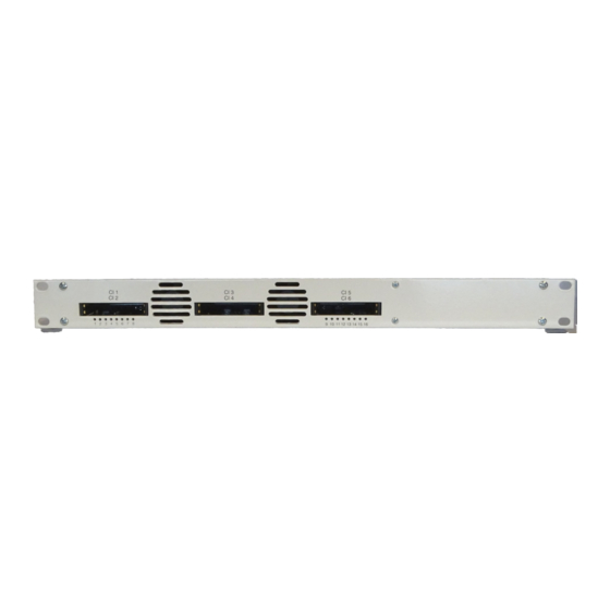
1.7. Display elements and connectors 1.7.1. MK 8/160x 1. LED indicators Green = modulation is ok Green (blinking) = something is missing from the programmed TS = modulator overload. 2. Equipotential bonding connection 3. Mains connection 4. HF input LEDs: Yellow = MPEG data stream present, Off = MPEG data stream not present 5. -
Page 8: Mounting And Installation
2. Mounting and Installation Installation must be performed by authorized and skilled electricians only. Before mounting and installation, pull the mains plug (1)! The antenna system must be installed and grounded according to the EN 60728-11 standard. The compact headend can be mounted on either at the wall or be mounted in a 19 "rack. -
Page 9: Equipotential Bonding
Slide the compact headend into the 19 "rack. Screw the compact headend with four screws (2). Maintain the EN 60728-11. 2.3. Equipotential bonding To connect the outer conductor of the coaxial cable to the equipotential bonding, use e.g. QEW earthing angles or CFA earth connection blocks at the inputs and output (see 2.5 on page 10). -
Page 10: Rf Installation
2.5. RF Installation 2.5.1. Connection to DVB-T/T2 or DVB-C Before connecting the antenna cabel, the LNB power has to be switched off (see 3.3.2 on page 16). Active DVB-T antennas have to be supplied by an external power supply. 2.5.2. Connection to DVB-S/S2/S2x Connection to the LNBs On the SAT-IF input the compact headends have a remote supply voltage for the LNB and use DiSEqC 1.0... -
Page 11: Connection To The Internet
2.5.4. Connection to the Internet Connection via Ethernet over Coax to a router which is connected to the Internet. Connection via EoC 2-01 in „Bridge Client Mode“ to a WLAN router. 2018-01-31 | Technical improvements, changes in design, printing- and other errors expected. -
Page 12: Configuration
3. Configuration The device is configured via the graphical user interface of the integrated web interface. To access the user interface, you need a standard PC/laptop with a network interface and the actual version of the installed web browser. To connect the network interface of the headend to the computer, you need a commercially available network cable. - Page 13 Enter the default password: Ramsen8262 Click ENTER PASSWORD. If you are not automatically forwarded to the start page, click OPEN PAGE. The standard language of the user interface is English. In the header, the the language of the user interface can be changed.
-
Page 14: Front Page
3.2. Front page The relevant information required for the function of the system are shown on the front page. The decisive thing is the quality of the signals at the INPUT and the utilization of the modulators at the OUTPUT. 3.2.1. -
Page 15: Initialization Phase 1
The number of choosen programmes (see 3.4 on page 17) and the configuration of the modulators (see 3.5 on page 22) have an influence to the fill level. 3.3. Initialization phase 1 Choose INITIALIZATION from the main menu. During the first phase of the initialization, the tuner settings required for the scan are made and the station scanning is carried out. -
Page 16: Dvb-C, Dvb-T Or Dvb-T2
3.3.2. DVB-C, DVB-T or DVB-T2 Before connecting an antenna cable to an tuner, the LNB Power has to be set to Off Click TUNER 1…4 to select one tuner. In the field LNB power choose the option Off. Enter 3- digits for center frequency Choose “Off”... -
Page 17: Found Programmes
3.3.4. Found programmes After a successful station scanning, the radio and TV stations are shown in the area FOUND PROGRAMS. The table contains information about the Program Name, the Type and the Encryption. 3.4. Initialization phase 2 In the initialization PHASE 2, the found programmes are subdivided by tuner. ... -
Page 18: Remux Mode
3.4.1. Remux mode If the the Network ID are set on auto, the device works in the Remux mode. In this mode, the IDs from the set transponder and from the satellite are used and forwarded to the modulators with virtually no changes. The TS ID1 to TS ID8 of the four modulators, are also set on auto. - Page 19 Change the Network ID to a value greater than zero. Click on SAVE CHANGES. The IDs of the transport streams TS ID1 to TS ID8 are automatically incremented by one to four, the cross multiplex mode is activated. Important: The CROSS MULTIPLEX MODE can not be used for CA programmes, which are encrypted in the haedend! ...
- Page 20 Spliting the programmes of a transonder If there are to much programms transmitted in one transponder, they can be splitted to several modulators. The programms of one transponder are spitted to two modulators For example: choose modulator M1 for two programmes and modulator M2 for two other programmes. Service ID Changes of the Service ID are only necessary for STBs using fix preset IDs.
-
Page 21: Lcn (Logical Channel Numbering)
3.4.3. LCN (Logical Channel Numbering) During the scan of TV stations, the stations are usually saved in the sequence of the channel lists in tuner 1-4. The LCN function enables channel allocation for the station scan of the TV devices. The TV device must support the LCN function. -
Page 22: Initialization Phase 3 - Dvb-C
3.5. Initialization phase 3 – DVB-C Note: Depending on the modulation standard the signals are modulated into DVB-C or DVB-T (see 3.7.2 on page 28). In phase 3, the modulators are configured. Click on PHASE 3, to modify the setting of the modulator. The output channels are compulsory assigned to adjacent channels. -
Page 23: Fill Level
3.5.2. Fill level The fill level depends on the number of activated channels in the channel list (menu item Phase 2) If the CROSS MULTIPLEX MODE is active, it must be ensured that the maximum number of activated channels in one modulator is not exceeded. -
Page 24: Initialization Phase 3 - Dvb-T
3.6. Initialization phase 3 – DVB-T Note: Depending on the modulation standard the signals are modulated into DVB-C or DVB-T (see 3.7.2 on page 28). In phase 3, the modulators are configured. After assigning programmes to the modulator the fill level has to be conntrolled. With the parameters of the modulator, the datarate can in certain circumstances be reduced. - Page 25 DVB-T FEC (forward Thanks to the error correction, errors resulting from high-disturbed error correction): transmission routes can be balanced by restoring data. The data required to restore the signal are included in the transmitted FEC bits. Changing the FEC factor modifies the part of the FEC data in relation to the application data.
-
Page 26: Fill Level
3.6.2. Fill level The data rate of the sender may vary depending on the image contents and on the transmission quality. To ensure an undisturbed reception, a reserve must absolutely be observed. We recommend you to set the maximal fill level to 90%. If the current fill level exceeds the maximal fill level, it may cause image disturbances, e.g. -
Page 27: Selected Programmes
3.6.3. Selected Programmes The programme table SELECTED PROGRAMS shows the programmes that were activated in phase 2. 3.7. Maintenance The menu entry MAINTENANCE enables software updates, changing the IP address, changing the password, restarting the headend and erasing service data. Under Current Settings, you will find the following information: ... -
Page 28: Modulation Standard
Click under SOFTWARE FILE on „Browse…“. Browse for the file on your computer. Click on UPDATE. The file will be uploaded to the device. After this the update of the device begins, the remaining time ist shown as a countdown. The headend will be automatically rebooted after an update. -
Page 29: Changing The Ip Address
The headend will be automatically rebooted, the enter password dialog will be displayed. Enter the password again. Check especially the modulator settings and their fill level. 3.7.3. Changing the IP address The network options are configured under the menu item MAINTENANCE> SYSTEM OPTIONS. Dynamic IP adress ... -
Page 30: Changing The Password
Click SAVE & REBOOT to confirm and save the changes. When the changes are saved, the device will reboot automatically. The new IP address has to be entered in the web browser and the enter password dialog will be displayed. 3.7.4. -
Page 31: Save Initialization Data
3.7.7. Save Initialization Data In the section SAVE SYSTEM INITILIZATION DATA TO FILE you can save the current initilization data from phase 1 to 3 into a file on your computer. Click on SAVE. The data will be saved in a file called config.dat at the download folder on your computer. ... -
Page 32: Device Name
Prerequisite is an internet connection for the headend. In the State field, select Enabled. Activate, if required, the option AXING support allowed. In the field Location, enter a name for the location of the headend. This name will appear later in the SMARTPortal to help you identify the headend. -
Page 33: Log Files
3.7.11. Log files In the section LOGS you can view the Log files . Choose Status Log. The status log is written to RAM and starts again after a restart. In the status log for example, the lock in time and the frequencies of the tuners are stored. -
Page 34: Use Of Ca Modules
4. Use of CA modules 4.1. Insertion of CA modules Up to six CA modules can be inserted into the CI-slots at the front side of the MK 8-06 or MK 16-06. Carefully insert the CA modules to the corresponding CI slot without exerting force. 4.2. -
Page 35: Decryption Of Programmes
Use Up or Down to reach a higher or lower selection point. Use Ok to enter a corresponding sub menu or confirm a selection. Use Menu to come back to the next superordinate level. Use Exit to leave the menu. 4.3. -
Page 36: Technical Specifications
5. Technical specifications MK 800/MK 806 MK 1600/MK 1606 Input tuner 8 × DVB- 16 × DVB- S/S2/S2x/T/T2/C S/S2/S2x/T/T2/C Input frequency range DVB-C | DVB-T/T2 | DVB- 50…898 MHz | 900…2150 MHz S/S2/S2X Input level DVB-C | DVB-T/T2 | DVB- 49…84 dBµV | 39…84 dBµV | 43...84 dBµV S/S2/S2X LNB voltage...
Need help?
Do you have a question about the RF MK 800 and is the answer not in the manual?
Questions and answers