
Related Manuals for axing MK 8-0 Series


Summary of Contents for axing MK 8-0 Series
- Page 1 CHP - Compact High Performance Kopfstellen MK 8-0x | MK 16-0x | MK 8-2x MK 8-0xN | MK 12-0xN DVB-Kopfstellen Betriebsanleitung...
-
Page 2: Table Of Contents
Betriebsanleitung | MK 8-0x | MK 16-0x | MK 8-2x | MK 8-0xN | MK 12-0xN Inhaltsverzeichnis Produktbeschreibung ..............................5 1.1. Allgemeines ................................5 1.2. Lieferumfang ................................. 5 1.3. Verfügbares Zubehör ............................. 6 1.4. Eingänge ................................6 1.4.1. MK 8-0x | MK 16-0x | MK 8-2x ........................6 1.4.2. - Page 3 5.3.1. IP-Adresse ändern ............................48 5.3.2. Passwort ändern ............................49 5.3.3. Gerätenamen eingeben..........................49 5.4. Config ................................. 49 5.4.1. Programmdaten löschen ..........................49 5.4.2. Initialisierungsdaten speichern ........................50 5.4.3. Initialisierungsdaten laden ......................... 50 5.4.4. Senderliste für alle Geräte.......................... 51 5.5. Reboot ................................
- Page 4 Benutzen Sie das Gerät ausschließlich wie in dieser Betriebsanleitung beschrieben und insbesondere nach dem Stand der Technik. Wird das Gerät für andere Einsätze verwendet, wird keine Gewährleistung übernommen! Hiermit erklärt die AXING AG, dass die gekennzeichneten Produkte den geltenden Richtlinien entsprechen. WEEE Nr. DE26869279 | Elektrische und elektronische Komponenten nicht mit dem Restmüll, sondern separat entsorgen.
-
Page 5: Produktbeschreibung
NIT-Editiermöglichkeit • PID-Filtering • Schnittstelle für CASimulcrypt Server • Klasse A gemäß EN 50083-2 • Web-basierte Konfiguration, für AXING SMARTPortal geeignet • Unterstützt SNMPv1 und SNMPv2c • Für Wandmontage oder als 19"-Einheit verwendbar 1.2. Lieferumfang 1 × Kompakt-Kopfstelle 1 × Netzkabel 1 ×... -
Page 6: Verfügbares Zubehör
Betriebsanleitung | MK 8-0x | MK 16-0x | MK 8-2x | MK 8-0xN | MK 12-0xN 1.3. Verfügbares Zubehör MKS 1-00 Softwareerweiterung zum Editieren einer NIT MKS 1-01 Softwareerweiterung zum PID-Filtering MKS 1-02 Softwareerweiterung für CASimulcrypt MKZ 1-00 Frontplatte für 19"-Einbau (MK 8-00/MK 16-00) MKZ 1-01 Frontplatte für 19"-Einbau, mit Öffnungen für CI-Slots (MK 8-06/MK 16-06) MKZ 1-02... -
Page 7: Mk 8-0Xn | Mk 12-0Xn
1.4.2. MK 8-0xN | MK 12-0xN MK 8-0xN | MK 12-0xN können DVB-S/S2/S2X empfangen. 1.5. Demodulation des Datenstroms In den Tunern erfolgt die Auswahl der Empfangsfrequenz und die Demodulation des Datenstroms. Im Remux-Verfahren können die Programme aus dem Datenstrom bei Bedarf gefiltert werden. Im Cross-Multiplexverfahren können FTA-Programme (Free to Air) aus den Datenströmen mehrerer Tuner für einen gemeinsamen Ausgangskanal gefiltert und neu gebündelt werden. -
Page 8: Grafische Benutzeroberfläche
Router (siehe z. B. 2.6 auf Seite 16). Durch das SMARTPortal sind die Konfiguration der Einstellungen oder Software-Updates von überall möglich. In Problemfällen oder auf Kundenwunsch ist auch eine Unterstützung und Fehleranalyse durch den AXING Support möglich. Zusätzlich sendet das SMARTPortal auch Fehlermeldungen an eine konfigurierte E-Mail-Adresse. Dadurch wird die Überwachung der Geräte einfach und sicher. -
Page 9: Anzeigeelemente Und Anschlüsse
1.9. Anzeigeelemente und Anschlüsse 1.9.1. MK 8-0x | MK 16-0x LED-Anzeigen für 8 bzw. 16 Ausgansmodulatoren Grün = Modulation OK Grün blinkend = Transportstream unkorrekt = Füllstand des Modulators zu hoch Potentialausgleichsanschluss Netzanschluss HF-Eingangs-LEDs: Gelb = MPEG-Datenstrom vorhanden, Aus = MPEG-Datenstrom nicht vorhanden HF-Eingänge 1 bis 4 HF-Eingänge 5 bis 8 HF-Eingänge 9 bis 12 (nur MK 16-0x) -
Page 10: Mk 8-0Xn | Mk 12-0X
Betriebsanleitung | MK 8-0x | MK 16-0x | MK 8-2x | MK 8-0xN | MK 12-0xN 1.9.2. MK 8-0xN | MK 12-0x Eine LED für alle Ausgansmodulatoren Grün Modulation OK Grün blinkend kein Datenstrom am Ausgang (kein Eingangssignal, Tuner nicht konfiguriert, kein Programm für Ausgang konfiguriert) Füllstand mindestens eines Modulators zu hoch Potentialausgleichsanschluss... -
Page 11: Mk 8-2X
Welches verschlüsselte Programm über welches Interface entschlüsselt wird, bestimmen Sie in der Konfiguration. 1.10. Application Notes Rund um die Installation und Konfiguration der AXING-Kopfstellen finden Sie Application Notes auf der AXING- Website. https://axing.com/service/application-notes/ Hier finden Sie Lösungen für den Betrieb der Sky Q Receiver an der MK-Kopfstelle. -
Page 12: Montage Und Anschluss
Betriebsanleitung | MK 8-0x | MK 16-0x | MK 8-2x | MK 8-0xN | MK 12-0xN 2. Montage und Anschluss Die Kompakt-Kopfstellen können entweder an der Wand montiert werden oder in einem 19“-Rack eingebaut werden. Montage und Anschluss sind nur von autorisierten Elektrofachkräften durchzuführen. ... -
Page 13: Wandmontage Mk 8-0Xn Und Mk 12-0Xn
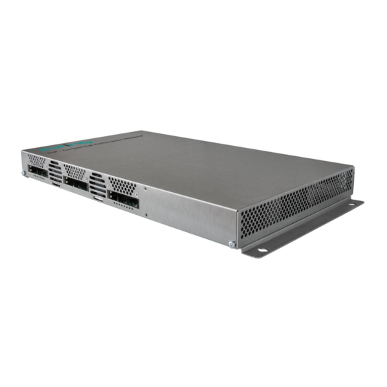
2.2. Wandmontage MK 8-0xN und MK 12-0xN Die Kopfstellen MK 8-0xN und MK 12-0xN besitzen an der Unterseite Montagelöcher, mit denen sie an vier passenden Schrauben an der Wand aufgehängt werden können. Wir empfehlen die Kopfstelle auf einer Lochblech-Montageplatte QMP 4065 oder größer zu montieren. Die folgende Abbildung zeigt die Positionen der vier anzubringenden Befestigungsschrauben. -
Page 14: Montage Im 19"-Rack
Betriebsanleitung | MK 8-0x | MK 16-0x | MK 8-2x | MK 8-0xN | MK 12-0xN Verwenden Sie vier passende Montageschrauben. L = abhängig von der Montageform und vom Montageuntergrund Schrauben Sie die Montageschrauben bis auf 1,5 mm z. B. in die Montageplatte. ... -
Page 15: Potentialausgleich
2.4. Potentialausgleich Die Kopfstelle muss gemäß EN 60728-11 am Potentialausgleich angeschlossen werden. Verwenden Sie den Potenzialausgleichsanschluss am Gerät. Um den Außenleiter der Koaxialkabel am Potentialausgleich anzuschließen, verwenden Sie z. B.QEW Erdungswinkel oder CFA 7-01 Erdungsblöcke am Eingang und Ausgang. 2.5. -
Page 16: Anschluss An Dvb-T/T2 Oder Dvb-C (Nur Mk 8-0X, Mk 8-2X Und Mk 16-0X)
Betriebsanleitung | MK 8-0x | MK 16-0x | MK 8-2x | MK 8-0xN | MK 12-0xN 2.6.2. Anschluss an DVB-T/T2 oder DVB-C (nur MK 8-0x, MK 8-2x und MK 16-0x) Bevor Sie ein Antennenkabel anschließen, müssen Sie die LNB-Spannungsversorgung abschalten (siehe Abschnitt 4.1.2 auf Seite 23). -
Page 17: Verbindung Über Ethernet Over Coax Zu Einem Router
2.7.2. Verbindung über Ethernet over Coax zu einem Router 2.8. Verbindung mit einem CASimulcrypt Server (mit MKS 1-02) Die Kopfstelle kann mit einem CAS-Server verbunden werden. Die Verbindung kann über die Schnittstelle Control hergestellt werden. Vorrausetzungen: • Ein entsprechend konfigurierter CAS-Server muss vorhanden sein. Dieser ist weder Teil der Kopfstelle, noch wird der CAS-Server in diesem Dokument beschrieben. -
Page 18: Konfiguration
Betriebsanleitung | MK 8-0x | MK 16-0x | MK 8-2x | MK 8-0xN | MK 12-0xN 3. Konfiguration Die Konfiguration der Geräte erfolgt über die grafische Benutzeroberfläche der integrierten Webschnittstelle. Für den Zugriff auf die Benutzeroberfläche benötigen Sie einen handelsüblichen PC/Laptop inklusive Netzwerkschnittstelle und die aktuelle Version des installierten Webbrowsers. -
Page 19: An- Und Abmelden
3.1. An- und Abmelden Die Benutzeroberfläche ist gegen unbefugten Zugriff geschützt. Beim Zugriff auf die Benutzeroberfläche erfolgt als erstes die Passwortabfrage. Geben sie das werksseitig eingestellte Passwort ein: Ramsen8262 Klicken Sie auf ENTER PASSWORD. Sollten sie nicht automatisch zu der Startseite weitergeleitet werden, klicken Sie anschließend auf OPEN PAGE. -
Page 20: Startseite
Betriebsanleitung | MK 8-0x | MK 16-0x | MK 8-2x | MK 8-0xN | MK 12-0xN 3.2. Startseite Auf der Startseite werden die für die Funktion des Systems maßgeblichen Informationen angezeigt. Entscheidend ist die Signalqualität am EINGANG und die Auslastung der Modulatoren am AUSGANG. 3.2.1. -
Page 21: Alarme
3.2.3. Alarme Wenn Alarme, Warnungen oder Meldungen der Kopfstelle aktiv sind, dann werden diese nach dem Einloggen auf der Startseite angezeigt. Das Beispiel zeigt eine Warnung zum CA-Modul 2. 2022-07-27 | Technische Verbesserungen, Änderungen im Design, Druckfehler und Irrtümer vorbehalten. -
Page 22: Initialisierung
Betriebsanleitung | MK 8-0x | MK 16-0x | MK 8-2x | MK 8-0xN | MK 12-0xN 4. Initialisierung 4.1. Initialisierung - Phase 1 Wählen Sie im Hauptmenü INITIALISIERUNG. In der ersten Phase der Initialisierung werden die für den Sendersuchlauf nötigen Tuner-Einstellungen vorgenommen und der Sendersuchlauf durchgeführt. -
Page 23: Dvb-C, Dvb-T Oder Dvb-T2 (Nur Mk 8-0X, Mk 8-2X Und Mk 16-0X)
4.1.2. DVB-C, DVB-T oder DVB-T2 (nur MK 8-0x, MK 8-2x und MK 16-0x) Bevor Sie ein Antennenkabel anschließen, müssen Sie die LNB-Versorgung ausschalten. Mit der Schaltfläche TUNER 1…8/12/16 einen Tuner auswählen. Im Feld LNB-Versorgung die Option aus auswählen! ... -
Page 24: Bitfehlerrate
Betriebsanleitung | MK 8-0x | MK 16-0x | MK 8-2x | MK 8-0xN | MK 12-0xN 4.1.3. Bitfehlerrate Im mittleren Bereich wird die BITFEHLERRATE angezeigt. Es wird die Anzahl der fehlerhaften Bits von 1.000.000 übertragenen Bits ermittelt. 4.1.4. Gefundene Programme Nach einem erfolgreichen Suchlauf werden im Bereich GEFUNDENE PROGRAMME die Radio- und TV-Sender angezeigt. -
Page 25: Initialisierung - Phase 2
4.2. Initialisierung - Phase 2 Klicken Sie auf PHASE 2, um zur Programmauswahl zu gelangen. Die gefundenen Programme werden nach Tunern gegliedert aufgelistet. Nach dem Sendersuchlauf in Phase 1 sind zunächst keine Programme aktiviert. In der Spalte Modulator gibt es farbige Schaltflächen M1 bis M8/M12/M16. Die Schaltflächen entsprechen den Modulatoren der Kopfstelle. -
Page 26: Remux-Mode
Betriebsanleitung | MK 8-0x | MK 16-0x | MK 8-2x | MK 8-0xN | MK 12-0xN 4.2.1. Remux-Mode Wenn die Netzwerk-ID auf den Wert auto eingestellt ist, befindet sich das Gerät im REMUX MODE. In diesem Modus werden die IDs der eingestellten Transponder und Satelliten übernommen und unverändert an die Modultoren weitergeleitet. - Page 27 Auswahl der Programme Im Remux-Mode ist jeder Tuner einem Modulator fest zugeordnet. Die Programme des Tuners können ausschließlich dem zugeordneten Modulator zugewiesen werden. Klicken Sie z. B. in der Tabelle TUNER 1 auf die Modulator-Schaltflächen M1. Das Programm wird dem Modulator 1 zugeordnet. Die Modulator-Schaltfläche wird farblich hervorgehoben (durch erneutes Klicken wird die Zuordnung wieder aufgehoben.
-
Page 28: Cross-Multiplex-Mode
Betriebsanleitung | MK 8-0x | MK 16-0x | MK 8-2x | MK 8-0xN | MK 12-0xN 4.2.2. Cross-Multiplex-Mode Der Cross-Multiplex-Mode dient • zum Splitten von Transpondern • zum Zusammenführen von Programmen aus mehreren Transpondern in einem gemeinsamen Ausgangskanal Dadurch werden die vorhandenen Übertragungskapazitäten besser genutzt. ... - Page 29 Zusammenführen von Programmen in gemeinsamen Modulatoren Im Cross-Multiplex-Mode ist die Zuordnung der Tuner zu den Modulatoren aufgehoben. Modulator 2 zugeordnete Programme Klicken Sie z. B. in der Spalte Modulator jeweils auf M2. Die Programme werden dem Modulator 2 zugeordnet. Aufteilen der Programme eines Transponders Wenn sich zu viele Programme auf einem Transponder befinden.
-
Page 30: Eingangsmodus Auswählen
Betriebsanleitung | MK 8-0x | MK 16-0x | MK 8-2x | MK 8-0xN | MK 12-0xN 4.2.3. Eingangsmodus auswählen Für jeden Tuner kann zunächst ein Eingangsmodus im Auswahlfeld Input mode ausgewählt werden. • Standard Die Programme können im Remux-Modus zu den jeweiligen Modulatoren zugeordnet oder im Cross- Multiplex-Modus auf verschiedene Modulatoren verteilt werden •... -
Page 31: Programmnamen Ändern
4.2.5. Programmnamen ändern Der Programmname kann geändert werden. Der eingegebene Programmname erscheint später in der Kanalliste der angeschlossenen Fernsehgeräte. Klicken Sie auf eines der Programme. Die Tabelle mit Informationen zum Programm wird geöffnet. Klicken Sie rechts neben das Feld Program Name. ... -
Page 32: Pid-Remapping
Betriebsanleitung | MK 8-0x | MK 16-0x | MK 8-2x | MK 8-0xN | MK 12-0xN 4.2.7. PID-Remapping Automatisches PID-Remapping Sollten mehrere Programme innerhalb eines Ausgangsmodulators Pakete enthalten, die dieselbe PID haben, kann dies zu Störungen führen. Deswegen werden diese PIDs automatisch re-mapped. Im Beispiel sind beide Programme dem Modulator M1 zugeordnet (1). -
Page 33: Pid-Filtering Mit Mks 1-01
Manuelles Remappen Sollen Pakete eine bestimmte OUT PID erhalten, dann kann diese manuell eingegeben werden. Klicken Sie beim entsprechenden Programm in die Spalte OUT PID. Geben Sie die PID mit der Tastatur ein oder erhöhen/verringern Sie die PID mit den Pfeiltasten. ... -
Page 34: Epg- Und Eit-Optionen
Betriebsanleitung | MK 8-0x | MK 16-0x | MK 8-2x | MK 8-0xN | MK 12-0xN 4.2.9. EPG- und EIT-Optionen Eingang für Electronic Program Guide (EPG) Nur im Remux-Mode möglich: Wenn ein Satellit den EPG auf einem speziellen Transponder zur Verfügung stellt, dann kann der Tuner, der diesen Transponder empfängt, als EPG-Eingang ausgewählt werden. -
Page 35: Nit-Version „Einfrieren
4.2.11. NIT-Version „einfrieren“ Wenn sich Programme eines Transponders ändern, dann wird die NIT neu erstellt. In der Regel merkt der Endanwender davon nichts, weil die Receiver die neue NIT automatisch einlesen. In manchen Ländern (z.B. Frankreich) werden aber die Endanwender dazu aufgefordert, einen Sendersuchlauf zu starten. Kommt es nun zu dem Fall, dass ein oder mehrere Sender nur schwach zu empfangen sind, dann ändert sich die NIT häufig und die Endanwender werden immer wieder unnötigerweise zum Sendersuchlauf aufgefordert. - Page 36 Betriebsanleitung | MK 8-0x | MK 16-0x | MK 8-2x | MK 8-0xN | MK 12-0xN Wählen Sie unter Tuner einen der verfügbaren Tuner aus. Geben Sie unter In PID eine nicht referenzierte PID ein. Wählen Sie den Ausgangs-Modulator aus. ...
-
Page 37: Initialisierung - Phase 3
4.3. Initialisierung - Phase 3 Hinweis: Abhängig vom konfigurierten Modulationsverfahren bzw. abhängig vom Gerätetyp werden die Signale DVB-C, DVB-T oder DVB-T2 moduliert (siehe 4.4 auf Seite 47). In der Phase 3 wird die Konfiguration der Modulatoren vorgenommen. Klicken Sie auf PHASE 3, um zur Modulator-Konfiguration zu gelangen. 4.3.1. -
Page 38: Mk 8-0X, Mk 16-0X, Mk 8-0Xn Und Mk 12-0Xn (Dvb-T)
Betriebsanleitung | MK 8-0x | MK 16-0x | MK 8-2x | MK 8-0xN | MK 12-0xN Um den störungsfreien Empfang zu gewährleisten ist unbedingt eine Reserve einzuhalten. Wir empfehlen einen maximalen Füllstand von 90%. Wird der maximale Füllstand überschritten kann es zu Bildstörungen wie z. Bsp. Mosaikbilder kommen. - Page 39 Parameter Norm: Legt die Norm für das Ausgangskanalraster im Feld Ausgangskanal fest. Hinweis: Eine Änderung der Norm folgt den folgenden Regeln: CCIR -> Australien: Die Bandbreite aller Modulatoren wird auf 7 MHz geändert Australien -> CCIR: Die Bandbreite der Modulatoren wird auf 8 MHz geändert, aber die niedrigen Kanäle S2-S20 bleiben auf 7 MHz Bandbreite Ausgangskanal: Jeder der Modulatoren lässt sich auf einen beliebigen Ausgangskanal zwischen...
- Page 40 Betriebsanleitung | MK 8-0x | MK 16-0x | MK 8-2x | MK 8-0xN | MK 12-0xN DVB-T Guard Interval: Zwischen den gesendeten Symbolen des Nutzsignales wird ein Schutzintervall übertragen. Durch dieses Schutzintervall wird bei der DVB-T Übertragung das Symbolübersprechen vermieden. Die verzögert eintreffenden Signale von weiteren synchronisierten DVB-T Sendern oder Reflektionen haben keine Auswirkung auf die Decodierung des Nutzsignals, wenn sie während des Schutzintervalls eintreffen.
- Page 41 Modulation Coderate Guard interval (Schutzintervall) 1/16 1/32 QPSK 4,976 5,529 5,855 6,032 6,635 7,373 7,806 8,043 7,465 8,294 8,782 9,048 8,294 9,216 9,758 10,053 8,709 9,676 10,246 10,556 16-QAM 9,953 11,059 11,709 12,064 13,271 14,745 15,612 16,086 14,929 16,588 17,564 18,096 16,588 18,431...
-
Page 42: Mk 8-2X (Dvb-T2)
Betriebsanleitung | MK 8-0x | MK 16-0x | MK 8-2x | MK 8-0xN | MK 12-0xN 4.3.3. MK 8-2x (DVB-T2) Modulator-Konfiguration Auswahl eines Modulators Wählen Sie links aus MODULATOR 1 bis MODULATOR 4 bzw. MODULATOR 8 einen Modulator aus. ... - Page 43 Durch das Verstellen der Bandbreite entsprechen die Kanäle nicht mehr dem durch die Norm vorgegebenen Kanalraster. Guard Interval Zwischen den gesendeten Symbolen des Nutzsignales wird ein Schutzintervall übertragen. Durch dieses Schutzintervall werden Störungen durch Symbolübersprechen vermieden. Ein sehr langes Schutzintervall (z. Bsp. 1/4) führt zu einer geringen Datenrate. Bei der Übertragung in einem koaxialen Verteilnetz reicht i.
- Page 44 Betriebsanleitung | MK 8-0x | MK 16-0x | MK 8-2x | MK 8-0xN | MK 12-0xN Füllstand Die Datenrate der Sender kann abhängig vom Bildinhalt und der Übertragungsqualität variieren. Um den störungsfreien Empfang zu gewährleisten ist unbedingt eine Reserve einzuhalten. Wir empfehlen einen maximalen Füllstand von maximal 90%.
-
Page 45: Wartung
5. Wartung Im Menüpunkt WARTUNG können Statusinformationen der Kopfstelle eingesehen werden und die technischen Randbedingungen konfiguriert werden. 5.1. STATUS 5.1.1. Aktuelle Einstellungen Unter AKTUELLE EINSTELLUNGEN finden Sie folgende Informationen: • Firmware-Version: Zeigt die Version der Firmware und den Typ der Ausgangsmodulation an. •... -
Page 46: Software Aktualisieren
Kopfstellen mit einer älteren Software-Version geladen werden. Nehmen Sie deswegen möglichst ein Software-Update aller Kopfstellen vor. Wir empfehlen zum leichteren Handling und Überblick das AXING SMARTPortal (siehe 1.9 auf Seite 8). Download Sie finden Software-Updates zum Download indem Sie auf www.axing.com im Suchfeld den Artikel eingeben. -
Page 47: Output
5.2. Output 5.2.1. Modulationsverfahren MK 8-0x, MK 16-0x, MK 8-0xN und MK 12-0xN Abhängig vom konfigurierten Modulationsverfahren werden die Ausgangssignale in DVB-C oder DVB-T moduliert. MK 8-2x Abhängig vom konfigurierten Modulationsverfahren werden die Ausgangssignale in DVB-T2 8x16K oder DVB- T2 4x32K moduliert. •... -
Page 48: System
Betriebsanleitung | MK 8-0x | MK 16-0x | MK 8-2x | MK 8-0xN | MK 12-0xN 5.3. System 5.3.1. IP-Adresse ändern Unter dem Menüpunkt SYSTEMOPTIONEN werden die Netzwerkoptionen konfiguriert. Dynamische IP-Adresse Verwenden Sie dynamische IP-Adresse, um das Gerät in ein Netzwerk mit DHCP-Server einzubinden. Statische IP-Adresse ... -
Page 49: Passwort Ändern
5.3.2. Passwort ändern Das werkseitig eingestellte Passwort lautet: Ramsen8262. Nach der ersten Inbetriebnahme der Kopfstelle sollte das werkseitig eingestellte Passwort sofort geändert werden. Unter PASSWORT kann das Passwort geändert werden. Geben Sie ein neues Passwort mit 8 bis 10 Buchstaben und/oder Zahlen ein. ... -
Page 50: Initialisierungsdaten Speichern
Betriebsanleitung | MK 8-0x | MK 16-0x | MK 8-2x | MK 8-0xN | MK 12-0xN 5.4.2. Initialisierungsdaten speichern Unter EINSTELLUNGEN DER INITIALISIERUNG ALS DATEI SPEICHERN können die aktuellen Einstellungen der Initialisierungsphasen 1 bis 3 in einer Datei gespeichert werden. ... -
Page 51: Senderliste Für Alle Geräte
5.4.4. Senderliste für alle Geräte Sie können für alle Geräte, die sich im Netzwerk befinden und für die dieselbe Ausgangsmodulation eingestellt ist, eine gemeinsame Senderliste erstellen. Wählen Sie die Kopfstellen aus, die in der Senderliste enthalten sein sollen. Hinweise: Das Gerät, an dem Sie angemeldet sind, ist als „Dieses Gerät“ bezeichnet und immer ausgewählt. -
Page 52: Smartportal
Zugang zum SMARTPortal Wenn Sie registrierter Nutzer des SMARTPortals sind, dann können Sie die Kopfstelle über das SMARTPortal fernwarten und ggf. Support von AXING erhalten (siehe auch https://axing.com/produkte/smartportal/). Voraussetzung ist eine Internetverbindung für die Kopfstelle. Wählen Sie im Feld Status die Option Aktiviert. -
Page 53: Snmp
Zielport der NMS eingeben, per Default wird 162 verwendet. MIB-Objekt-Definition Die MIB-Objekt-Definition sind im Gerät gespeichert. Klicken Sie auf AXING-MIB.txt, um die Definition zu öffnen. Alternativ können Sie, wenn Sie mit dem Gerät im Netzwerk verbunden sind, die Datei aus dem Gerät herunterladen: URL = [IP-Adresse des Geräts]/MIB/AXING-MIB.txt... - Page 54 Standardmäßig unterstützt die Kopfstelle das "SNMP v1/v2 Public" Profi l (Community-Name "public"). Folgende SNMP-Einstellungen müssen geändert werden, um auch die CPU-Last anzuzeigen: Wählen Sie Axing-Device → Settings Scrollen Sie nach unten zu "SNMP Compatibility Options". Deaktivieren Sie "Inherit from".
-
Page 55: Nit (Network Information Table)
5.8. NIT (Network Information Table) Die NIT enthält Informationen über die Signalkonfiguration einer Kopfstelle. Ein Endgerät benötigt diese Informationen für einen schnellen Programmsuchlauf. Die LCN (Logical Channel Numbering) befindet sich innerhalb der NIT, wodurch die Programme virtuell einem Speicherplatz des Empfangsgerätes zugeordnet werden. -
Page 56: Typ Auswählen
Hinweis: Nur mit der kostenpflichtigen Softwareerweiterung MKS 1-00 kann der Typ auf Manual gestellt werden und eine Network Information Table (NIT) aus den Geräten ausgelesen, editiert und wieder in die Geräte hochgeladen werden. Die MKS 1-00 muss durch den AXING-Support installiert werden (dazu ist eine Internet-Verbindung für die Kopfstelle nötig). -
Page 57: Nit Überprüfen
5.8.4. NIT Überprüfen Hinweis: Wird die NIT bearbeitet, so schaltet die Kassette automatisch in den Cross-Multiplex-Mode. Werte, die sich überschneiden Werte, die sich ggf. überschneiden werden rot dargestellt. Diese Fehler müssen vor dem Hochladen bereinigt werden. Hinweise: • Es müssen immer unterschiedliche TS-IDs vergeben werden •... -
Page 58: Hochladen Der Nit
Betriebsanleitung | MK 8-0x | MK 16-0x | MK 8-2x | MK 8-0xN | MK 12-0xN 5.8.6. Hochladen der NIT Wählen Sie die Geräte aus, in die die NIT hochgeladen werden soll. Klicken Sie auf HOCHLADEN. Die Daten werden hochgeladen und in der Kopfstelle gespeichert. 5.8.7. -
Page 59: Logs
5.9. Logs 5.9.1. Log-Einträge Unter LOGS können Sie sich die Log-Einträge der Kopfstelle anzeigen lassen. • Der Statuslog wird ins RAM geschrieben und ist nach einem Neustart leer. • Der Systemlog wird in den Flashspeicher geschrieben, ist also auch nach dem Neustart noch vorhanden. ... -
Page 60: Lizensen
Filtering/Erstellen einer NIT). Für eine Software-Erweiterung benötigen Sie eine Lizenz. Lizenzen erwerben Eine Lizenz können Sie erwerben, in dem Sie die entsprechende Software-Erweiterung bei AXING kaufen. Beim Kauf müssen Sie die Seriennummer der Kopfstelle angeben. Passend zu genau dieser Seriennummer wird eine Lizenzdatei für Sie generiert. - Page 61 Das Laden der Datei dauert einige Sekunden. Im Dialog AKTIVIERTE LIZENZEN wird die neue Lizenz aufgelistet. Starten Sie das Gerät neu, melden Sie sich nach dem Neustart erneut an und wechseln Sie zur gewünschten Sprache. Die Funktion ist erst nach einem Neustart der Kopfstelle verfügbar. 2022-07-27 | Technische Verbesserungen, Änderungen im Design, Druckfehler und Irrtümer vorbehalten.
-
Page 62: Casimulcrypt (Mit Mks 1-02)
Betriebsanleitung | MK 8-0x | MK 16-0x | MK 8-2x | MK 8-0xN | MK 12-0xN 5.11. CASimulcrypt (mit MKS 1-02) Die Einrichtung eines Conditional-Access-Systems setzt die Installation und Konfiguration eines CAS-Servers, der unter anderem ECMs und EMMs generiert, voraus. Die Einrichtung eines CAS-Servers wird in diesem Dokument nicht beschrieben. -
Page 63: Cas List
Name: Wird nur in der Konfigurations-Oberfläche verwendet, um die Scrambling-Gruppen leicht identifizieren zu können. Daher sollten die Gruppen beschreibende Namen haben, damit sie in Phase 2 bei der Verbindung von Programmen mit SCGs leicht identifiziert werden können. • Algorithm (Scrambling-Algorithmus), wählbare Optionen sind: # unscrambled (Scrambling für die SCG ist deaktiviert) # DVB-CSA-1 # DVB-CSA-2... -
Page 64: Ecm Generators
Betriebsanleitung | MK 8-0x | MK 16-0x | MK 8-2x | MK 8-0xN | MK 12-0xN 5.11.4. ECM Generators Der ECM-Generator wird vom CAS-Lieferanten bereitgestellt, um ECM-Nachrichten zu erzeugen. • Name: Wird nur in der Web-Schnittstelle verwendet, um ECMG-Server leicht zu unterscheiden. •... -
Page 65: Emm Configuration
5.11.6. EMM Configuration EMM enthält Informationen von CAS-Lieferanten, die z.B. die Berechtigungsstufen von Abonnenten oder Gruppen von Abonnenten angeben. Der EMM-Generator ist ein externer Server des CAS-Anbieters, der EMM- Nachrichten erzeugt und diese wiederholt an die Kopfstelle sendet. Die EMM-Konfiguration ist in zwei Tabellen unterteilt: EMM Generator List und EMM List. EMM Generator List: •... -
Page 66: Programm Verschlüsselung In Phase 2
Betriebsanleitung | MK 8-0x | MK 16-0x | MK 8-2x | MK 8-0xN | MK 12-0xN 5.11.7. Programm Verschlüsselung in Phase 2 Die Programme werden in Phase 2 mit den SCGs verbunden, um sie zu verschlüsseln: Klicken Sie auf das gewünschte Programm, um dessen Details anzuzeigen. ... -
Page 67: Verwenden Von Ca-Modulen
6. Verwenden von CA-Modulen 6.1. Einstecken der CA-Module In die CI-Steckplätze auf der Frontseite der MK 8-06, MK 8-26 und MK 16-06 können bis zu sechs CA-Module in die 6 CI-Steckplätze (CI1…CI6) gesteckt werden. In die CI-Steckplätze auf der Frontseite der MK 8-03N und MK 12-03 können bis zu drei CA-Module in die 3 CI- Steckplätze (CI1…CI3) gesteckt werden. -
Page 68: Verwenden Des Ci-Menüs
Betriebsanleitung | MK 8-0x | MK 16-0x | MK 8-2x | MK 8-0xN | MK 12-0xN 6.2.1. Verwenden des CI-Menüs Der Inhalt des CI-Menüs ist vom CAM-Hersteller und der verwendeten Karte abhängig. Je nach Hersteller sind verschieden Einstellungen möglich. Am wichtigsten sind die Informationen über Gültigkeit und Berechtigungen. -
Page 69: Entschlüsseln Von Programmen
6.3. Entschlüsseln von Programmen Nach dem Sendersuchlauf erkennen Sie verschlüsselte Programme in den Tuner-Tabellen am Kürzel CA in der Spalte Verschlüsselung. Werkseitig ist in der Spalte Entschlüsselung die Option no gewählt. Das Programm wird verschlüsselt an den Modulator übergeben und es muss am Empfangsgerät entschlüsselt werden. Wenn in den Kopfstellen CA-Module gesteckt sind, dann können die entsprechenden Programme entschlüsselt werden. -
Page 70: Technische Daten
Betriebsanleitung | MK 8-0x | MK 16-0x | MK 8-2x | MK 8-0xN | MK 12-0xN 7. Technische Daten 7.1.1. MK 8-00 | MK 8-06 | MK 16-00 | MK 16-06 MK 8-00 MK 8-06 MK 16-00 MK 16-06 Eingänge Anzahl Tuner 8 ×... - Page 71 1/4, 1/8, 1/16, 1/32 Symbolrate 1…7,5 MBaud/s @ DVB-C Schnittstellen Control/CAS 1 × RJ-45 Konformität Control/CAS IEEE 802.3, 100 Base-T Unterstützte HTTP, SNMP v1, SNMP v2c, AXING SMARTPortal** Konfigurations- Protokolle Allgemein Betriebsspannung 100…240 VAC/50…60 Hz Leistungsaufnahme 50 W 50 W...
-
Page 72: Mk 8-00N | Mk 8-03N | Mk 12-00N | Mk 12-03N
Betriebsanleitung | MK 8-0x | MK 16-0x | MK 8-2x | MK 8-0xN | MK 12-0xN MK 8-00 MK 8-06 MK 16-00 MK 16-06 Maße (B × H × T) ca. 480 × 253 × 47 mm Gewicht 2,55 kg 2,80 kg 2,90 kg 3,15 kg... - Page 73 1 … 7,5 MBaud/s @ DVB-C Schnittstellen Control/CAS 1 × RJ-45 Konformität Control/CAS IEEE 802.3, 100 Base-T Unterstützte Konfigurations- HTTP, SNMP v1, SNMP v2c, AXING SMARTPortal** Protokolle Allgemein Betriebsspannung 100 … 240 VAC/50 … 60 Hz Leistungsaufnahme 50 W 50 W...
- Page 74 Betriebsanleitung | MK 8-0x | MK 16-0x | MK 8-2x | MK 8-0xN | MK 12-0xN 7.1.3. MK 8-20 | MK 8-26 MK 8-20 MK 8-26 Eingänge Anzahl Tuner 8 × DVB-S/S2/S2X/T/T2/C 8 × DVB-S/S2/S2X/T/T2/C Anschluss 8 × F-Buchse Frequenzbereich 900…2150 MHz @ DVB-S/S2/S2X 50…898 MHz @ DVB-C 50…898 MHz @ DVB-T/T2...
- Page 75 1/128, 1/32, 1/16, 19/256, 1/8, 19/128, 1/4 Schnittstellen Control/CAS 1 × RJ-45 Konformität Control/CAS IEEE 802.3, 100 Base-T Unterstützte Konfigurations-Protokolle HTTP, SNMP v1, SNMP v2c, AXING SMARTPortal** Allgemein Betriebsspannung 100 … 240 VAC/50 … 60 Hz Leistungsaufnahme 50 W Potentialausgleichanschluss 4 mm²...
- Page 76 Betriebsanleitung | MK 8-0x | MK 16-0x | MK 8-2x | MK 8-0xN | MK 12-0xN 2022-07-27 | Technische Verbesserungen, Änderungen im Design, Druckfehler und Irrtümer vorbehalten.
- Page 77 CHP - Compact High Performance Headends MK 8-0x | MK 16-0x | MK 8-2x MK 8-0xN | MK 12-0xN DVB headends Operation instructions...
- Page 78 Operation instructions | MK 8-0x | MK 16-0x | MK 8-2x | MK 8-0xN | MK 12-0xN Table of contents Product description ................................. 5 1.1. General .................................. 5 1.2. Scope of delivery ..............................5 1.3. Available Accessories ............................6 1.4. Inputs ..................................
- Page 79 5.4.1. Erasing service data ........................... 49 5.4.2. Save Initialization Data ..........................50 5.4.3. Upload Initialization Data .......................... 50 5.4.4. Channel list for all devices ......................... 51 5.5. Reboot ................................51 5.5.1. Rebooting ..............................51 5.6. SMARTPortal ............................... 52 5.6.1. Access to SMARTPortal ..........................52 5.7.
- Page 80 If the device is used for other purposes, no warranty will be assumed! Herewith AXING AG declares that the marked products comply with the valid guidelines. WEEE Nr. DE26869279 | Electrical and electronic components must not be disposed of as residual waste, it must be disposed of separately.
-
Page 81: Product Description
1. Product description 1.1. General MK 8-00 8 independent multituner inputs Transmodulates 8 × DVB-S/S2/S2X/T/T2/C into 8 × DVB-C or DVB-T (depending on the configured modulation standard, see 5.2 on page 47) Expandable to 16 modulators with MKS 8-16 software. MK 8-06 Like MK 8-00, with 6 CI slots (see chapter 6 on page 67) MK 16-00... -
Page 82: Available Accessories
Operation instructions | MK 8-0x | MK 16-0x | MK 8-2x | MK 8-0xN | MK 12-0xN 1.3. Available Accessories MKS 1-00 Software extension to edit a NIT MKS 1-01 Software extension for PID filtering MKS 1-02 Software extension for CASimulcrypt MKZ 1-00 Front panel for 19"... -
Page 83: Mk 8-0Xn | Mk 12-0Xn
1.4.2. MK 8-0xN | MK 12-0xN MK 8-0xN | MK 12-0xN can receive DVB-S/S2/S2X. 1.5. Demodulation of the data stream The selection of the frequency and the demodulation of the data stream are both done in the tuner. If needed, the programs from the data flow of the demodulated transponder can be filtered (Remux mode). Thanks to the Cross Multiplex Mode, FTA programs (Free to Air) can be filtered from the data flow of several tuners for a common output channel and be bundled again. -
Page 84: Graphical User Interface
LAN, EoC, 3G/LTE-Router (see 2.6 on page 16). With AXING’s SMARTPortal a worldwide configuration of all settings or software updates can be ensured. On customer request AXING can provide the necessary support. -
Page 85: Display Elements And Connectors
1.9. Display elements and connectors 1.9.1. MK 8-0x | MK 16-0x 1. LED indicators for 8 or 16 output modulators Green modulation is ok Green (blinking) something is missing from the programmed TS Red = modulator overload. 2. Equipotential bonding connection 3. -
Page 86: Mk 8-0Xn | Mk 12-0Xn
Operation instructions | MK 8-0x | MK 16-0x | MK 8-2x | MK 8-0xN | MK 12-0xN 1.9.2. MK 8-0xN | MK 12-0xN One LED for all output modulators Green all modulators ok Green (blinking) no data stream at the output (no input signal, tuner not configured, no program for output configured) at least one modulator level too high overload. -
Page 87: Mk 8-2X
MK 8-26 have 6 CI slots (CI1 ... CI6). Which encrypted program you decrypt with which interface; you determine in the configuration. 1.10. Application Notes You can find application notes on the AXING website about the installation and configuration of AXING headends. https://axing.com/en/service/application-notes/... -
Page 88: Mounting And Installation
Operation instructions | MK 8-0x | MK 16-0x | MK 8-2x | MK 8-0xN | MK 12-0xN 2. Mounting and Installation The compact headend can be mounted on either at the wall or be mounted in a 19 "rack. Installation must be performed by authorized and skilled electricians only. ... -
Page 89: Wall Mounting Of Mk 8-0Xn And Mk 12-0Xn
2.2. Wall mounting of MK 8-0xN and MK 12-0xN The MK 8-0xN and MK 12-0xN head ends have mounting holes on the underside with which they can be hung on the wall using four suitable screws. We recommend mounting the headend on a perforated mounting plate QMP 4065 or larger. -
Page 90: Mounting In A 19"Rack
Operation instructions | MK 8-0x | MK 16-0x | MK 8-2x | MK 8-0xN | MK 12-0xN Use four suitable mounting screws. L = depending on the mounting form and the mounting surface Screw the mounting screws down to 1,5 mm, e.g. -
Page 91: Equipotential Bonding
Slide the compact headend into the 19 "rack. Screw the compact headend with four screws (2). Install the device in compliance with the safety regulations defined by the EN 60728-11 standard. 2.4. Equipotential bonding The device must be connected to the equipotential bonding according to EN 60728-11. Use the equipotential bonding connection at the device. -
Page 92: Connection To Dvb-T/T2 Or Dvb-C (Mk 8-0X, Mk 8-2X And Mk 16-0X Only)
Operation instructions | MK 8-0x | MK 16-0x | MK 8-2x | MK 8-0xN | MK 12-0xN 2.6.2. Connection to DVB-T/T2 or DVB-C (MK 8-0x, MK 8-2x and MK 16-0x only) Before connecting the antenna cabel, the LNB power has to be switched off (see 4.1.2 on page 23). Active DVB-T antennas have to be supplied by an external power supply. -
Page 93: Connection Via Ethernet Over Coax To A Router Which Is Connected To The Internet
2.7.2. Connection via Ethernet over Coax to a router which is connected to the Internet 2.8. Connecting to a CAS server (with MKS 1-02) The headend can be connected to a CAS server. The connection can be established via the the Control interface. -
Page 94: Configuration
Operation instructions | MK 8-0x | MK 16-0x | MK 8-2x | MK 8-0xN | MK 12-0xN 3. Configuration The device is configured via the graphical user interface of the integrated web interface. To access the user interface, you need a standard PC/laptop with a network interface and the actual version of the installed web browser. -
Page 95: Login And Logout
3.1. Login and logout The web-based user interface is protected against unauthorized access. When accessing the user interface, the first thing is the password request. Enter the default password: Ramsen8262 Click ENTER PASSWORD. If you are not automatically forwarded to the start page, click OPEN PAGE. -
Page 96: Front Page
Operation instructions | MK 8-0x | MK 16-0x | MK 8-2x | MK 8-0xN | MK 12-0xN 3.2. Front page The relevant information required for the function of the system are shown on the front page. The decisive thing is the quality of the signals at the INPUT and the utilization of the modulators at the OUTPUT. 3.2.1. -
Page 97: Alerts
3.2.3. Alerts If alerts, warnings, or messages of the head-end are active, then these are displayed on the start page after logging in. The example shows a warning about CA module 1. 2022-07-27 | Technical improvements, changes in design, printing- and other errors reserved. -
Page 98: Initialization
Operation instructions | MK 8-0x | MK 16-0x | MK 8-2x | MK 8-0xN | MK 12-0xN 4. Initialization 4.1. Initialization - phase 1 Choose INITIALIZATION from the main menu. During the first phase of the initialization, the tuner settings required for the scan are made and the station scanning is carried out. -
Page 99: Dvb-C, Dvb-T Or Dvb-T2 (Mk 8-0X, Mk 8-2X And Mk 16-0X Only)
4.1.2. DVB-C, DVB-T or DVB-T2 (MK 8-0x, MK 8-2x and MK 16-0x only) Before connecting an antenna cable to a tuner, the LNB Power has to be set to Off. Click TUNER 1…8/12/16 to select one tuner. In the field LNB power choose the option Off. ... -
Page 100: Bit Error Rate
Operation instructions | MK 8-0x | MK 16-0x | MK 8-2x | MK 8-0xN | MK 12-0xN If multistreams are to be received, then the PLS mode must be set to root or gold. In addition, the correct Stream ID (three digits) and the PLS code (six digits) must be entered. ... -
Page 101: Initialization - Phase 2
4.2. Initialization - phase 2 Click on PHASE 2, to select programs. The found programs are subdivided by tuner. After the station scanning in initialization phase 1 no programs are activated. In the Modulator column there are coloured buttons M1 to M8/M12/M16. The buttons correspond to the modulators of the headend. -
Page 102: Remux Mode
Operation instructions | MK 8-0x | MK 16-0x | MK 8-2x | MK 8-0xN | MK 12-0xN 4.2.1. Remux mode If the Network ID are set on auto, the device works in the Remux mode. In this mode, the IDs from the set transponder and from the satellite are used and forwarded to the modulators with virtually no changes. - Page 103 Assigning programs Every tuner is assigned to a modulator. The programs of the tuner can only be assigned to the associated modulator. For example, click in table TUNER 1 on M1. The program is assigned to modulator 1. The button of the modulator is highlighted in colour (a new click on a modulator allows the assignment to be cancelled.
-
Page 104: Cross Multiplex Mode
Operation instructions | MK 8-0x | MK 16-0x | MK 8-2x | MK 8-0xN | MK 12-0xN 4.2.2. Cross Multiplex Mode The cross-multiplex mode is used: • To split the programs of a transponder to several modulators. • To merge programs of several transponders into one output channel. Transmission capacities in the distribution networks can be optimized. - Page 105 Assigning programs to the modulators In the cross-multiplex mode, the tuners are no longer assigned to one modulator. Programs, assigned to modulator 2 Click in the column Modulator on M2. The programs are assigned to modulator 2. Splitting the programs of a transponder If there are to much programmes transmitted in one transponder, they can be splitted to several modulators.
-
Page 106: Choosing Input Mode
Operation instructions | MK 8-0x | MK 16-0x | MK 8-2x | MK 8-0xN | MK 12-0xN 4.2.3. Choosing input mode For each tuner, an input mode can be selected. • Default The programs can be assigned to the respective modulators in Remux mode or distributed to different modulators in cross-multiplex mode •... -
Page 107: Changing Program Name
4.2.5. Changing Program Name The name of a program can be changed. The entered program name will later appear in the channel list of the connected TV sets. Click on one of the programs. The table with the Information opens. ... -
Page 108: Pid-Remapping
Operation instructions | MK 8-0x | MK 16-0x | MK 8-2x | MK 8-0xN | MK 12-0xN 4.2.7. PID-Remapping Automatic PID remapping If several programs within an output modulator contain packets that have the same PID, this can cause interferences. Therefore these PIDs are re-mapped automatically. In the example, both programs are assigned to modulator M1 (1). -
Page 109: Pid Filtering (With Mks 1-01)
Re-mapping PIDs by hand If packets should get a very specific OUT PID, this can be entered manually. Click in the OUT PID column of the program. Enter the PID with the keyboard or increase/decrease the PID with the arrow keys. ... -
Page 110: Epg And Eit Options
Operation instructions | MK 8-0x | MK 16-0x | MK 8-2x | MK 8-0xN | MK 12-0xN 4.2.9. EPG and EIT options Electronic Program Guide (EPG) Only possible in Remux mode: If a satellite makes the EPG available on a special transponder, then the tuner receiving this transponder can be selected as the EPG input. -
Page 111: Freeze" Nit Version
4.2.11. "Freeze" NIT version If programs of a transponder change, then the NIT is recreated. In most countries, the end user does not notice, because the receivers automatically read in the new NIT. However, in some countries (eg France) end users are asked to start a channel search. - Page 112 Operation instructions | MK 8-0x | MK 16-0x | MK 8-2x | MK 8-0xN | MK 12-0xN Under Input, select one of the available input streams. Under In PID, enter an unreferenced PID. Select the output Modulator. ...
-
Page 113: Initialization - Phase 3
4.3. Initialization - phase 3 Note: Depending on the configured modulation standard or depending on the device type, the signals are modulated DVB-C, DVB-T or DVB-T2. (see 5.2 on page 47). In phase 3, the modulators are configured. Click on PHASE 3, to modify the setting of the modulator. 4.3.1. -
Page 114: Mk 8-0X, Mk 16-0X, Mk 8-0Xn And Mk 12-0Xn (Dvb-T)
Operation instructions | MK 8-0x | MK 16-0x | MK 8-2x | MK 8-0xN | MK 12-0xN Fill level The fill level depends on the number of activated channels in the channel list (menu item Phase 2) If the cross- multiplex mode is active, it must be ensured that the maximum number of activated channels in one modulator is not exceeded. - Page 115 Parameters Norm: In this selection field, you can set the norm for the output channel spacing. Note: Changing the norm works now according to following rules: CCIR-->Australia : all modulators forced to 7MHz Australia-->CCIR : all modulators forced to 8MHz, however with following exception: low channels S2-S20 are 7MHz only, so those remain in 7MHz Output channel: The first modulator can be set to any output channel between S2 and CH 69.
- Page 116 Operation instructions | MK 8-0x | MK 16-0x | MK 8-2x | MK 8-0xN | MK 12-0xN DVB-T guard interval: A guard interval is transmitted between the symbols of the useful signal. This guard interval avoids the intersymbol interference during the DVB-T transmission.
- Page 117 Modulation Code rate Guard interval 1/16 1/32 QPSK 4.976 5.529 5.855 6.032 6.635 7.373 7.806 8.043 7.465 8.294 8.782 9.048 8.294 9.216 9.758 10.053 8.709 9.676 10.246 10.556 16-QAM 9.953 11.059 11.709 12.064 13.271 14.745 15.612 16.086 14.929 16.588 17.564 18.096 16.588 18.431...
-
Page 118: Mk 8-2X (Dvb-T2)
Operation instructions | MK 8-0x | MK 16-0x | MK 8-2x | MK 8-0xN | MK 12-0xN 4.3.3. MK 8-2x (DVB-T2) Configuration of the modulators Select a modulator Select a modulator from MODULATOR 1 to MODULATOR 3 on the left. ... - Page 119 Bandwidth If CCIR is selected as the Norm, the bandwidth of the channels can be changed. With a larger bandwidth, more data can be transmitted in one channel. By adjusting the bandwidth, the channels no longer correspond to the channel grid specified by the Norm.
- Page 120 Operation instructions | MK 8-0x | MK 16-0x | MK 8-2x | MK 8-0xN | MK 12-0xN Fill level The data rate of the sender may vary depending on the image contents and on the transmission quality. To ensure an undisturbed reception, a reserve must absolutely be observed. We recommend you to set the maximal fill level to 90%.
-
Page 121: Maintenance
5. Maintenance In the menu item MAINTENANCE, status information of the head-end can be viewed, and the technical conditions can be configured. 5.1. STATUS 5.1.1. Current Settings Under Current Settings, you will find the following information: • Firmware version: Displays the firmware version and the output modulation type. •... -
Page 122: Updating Software
Software version. Therefore, if possible, make a Software update of all headends. We recommend the AXING SMARTPortal for easier handling and overview (see 1.9 on page 8) Download You can find software/firmware updates for download by entering the article in the search field on www.axing.com. -
Page 123: Output
5.2. Output 5.2.1. Modulation standard MK 8-0x, MK 16-0x, MK 8-0xN und MK 12-0xN Depending on the modulation standard the output signals are modulated into DVB-C or DVB-T. MK 8-2x Depending on the configured modulation standard, the output signals are modulated in DVB-T2 8x16K or DVB- T2 4x32K. -
Page 124: System
Operation instructions | MK 8-0x | MK 16-0x | MK 8-2x | MK 8-0xN | MK 12-0xN 5.3. System 5.3.1. Changing the IP address The network options are configured under the menu item SYSTEM OPTIONS. Dynamic IP adress Use dynamic IP address to connect the device to a network with a DHCP server. Static IP adress ... -
Page 125: Changing The Password
5.3.2. Changing the password The default password is: Ramsen8262. The default password should be changed right after commissioning the headend. Type an new password with 8-10 characters (letters and/or digits). Re-enter the password. Click SAVE CHANGES to confirm and save the changes. The saving of the password is confirmed. -
Page 126: Save Initialization Data
Operation instructions | MK 8-0x | MK 16-0x | MK 8-2x | MK 8-0xN | MK 12-0xN Click on erase. The frontpage will be shown. 5.4.2. Save Initialization Data In the section SAVE SYSTEM INITILIZATION DATA TO FILE you can save the current initilization data from phase 1 to 3 into a file on your computer. -
Page 127: Channel List For All Devices
5.4.4. Channel list for all devices You can create a common channel list for all devices with the same output modulation in the network. Select the headends to be included in the channel list. Notes: The device to which you are logged on is named "This device" and is always selected. You can only select headends with the same output modulation. -
Page 128: Smartportal
5.6.1. Access to SMARTPortal If you are a registered user of the SMARTPortal, then you can remotely control the device via the SMARTPortal and, if necessary, receive support from AXING (see also https://axing.com/en/produkte/smartportal/). Prerequisite is an internet connection for the headend. -
Page 129: Snmp
MIB object definition The MIB object definition is stored in the device. Click AXING-MIB.txt to open the definition. If you are connected to the device in the network, then you can download the file from the device. URL = [IP address of device] /MIB/AXING-MIB.txt For example: 192.168.0.145/MIB/AXING-MIB.txt... - Page 130 By default, the headend supports the "SNMP v1/v2 Public" profile (community name "public"). The following SNMP settings must be changed to also display the CPU load: Select Axing Device → Settings Scroll down to "SNMP Compatibility Options". Disable "Inherit from".
-
Page 131: Nit (Network Information Table)
5.8. NIT (Network Information Table) The NIT contains information about the signal configuration of a headend. A TV needs this information for a fast channel search. The LCN (Logical Channel Numbering) is located within the NIT, which virtually allocates the programs to a place. The headend provides an auto NIT at the factory, which includes all channels from 114 MHz to 1002 MHz and only the most important parameters such as symbol rate and modulation. -
Page 132: Select Type
Note: Only with the software extension MKS 1-00 can the type be set to Manual and a Network Information Table (NIT) be read from the devices, edited and uploaded back to the devices. The MKS 1-00 must be installed by AXING support (for this purpose, a connection with the Internet is necessary). 5.8.3. Read NIT Under STEP 1: READ NIT (DVB-C) the devices in the network are displayed. -
Page 133: Nit Check
5.8.4. NIT Check Note: If the NIT is edited, the headend automatically switches to cross-multiplex mode. Values that overlap Values that overlap are displayed in red. These errors must be cleaned up before uploading. Notes: • Different TS-IDs must always be assigned •... -
Page 134: Upload Nit To The Devices
Operation instructions | MK 8-0x | MK 16-0x | MK 8-2x | MK 8-0xN | MK 12-0xN 5.8.6. Upload NIT to the devices Select the devices you want to upload to. Click UPDATE. The data is uploaded and stored in the headend. 5.8.7. -
Page 135: Logs
5.9. Logs 5.9.1. Log entries Under LOGS you can see the log entries of the headend. • The system log is written to the flash memory, so it is still available after rebooting the headend. • The status log is written to RAM and is empty after rebooting the headend. ... -
Page 136: Licenses
Purchase licenses You can purchase a license by ordering the appropriate software extension from AXING. When ordering, you must provide the serial number of the headend. A license file will be generated for you to match exactly this serial number. Important: The license is bound to the serial number and is not transferable to other devices! - Page 137 Under UPLOAD A NEW LICENSE, select a LICENSE FILE. Click on UPLOAD. The upload will take a few seconds. The new license is listed in the ACTIVATED LICENSES dialog. Reboot the device and log in again. The new function is only available after a restart of the headend.
-
Page 138: Casimulcrypt (With Mks 1-02)
Operation instructions | MK 8-0x | MK 16-0x | MK 8-2x | MK 8-0xN | MK 12-0xN 5.11. CASimulcrypt (with MKS 1-02) The setup for the conditional access system requires the installation and configuration of a CAS server, which generates ECMs and EMMs, among other things. Setting up a CAS server is not described in this document. To configure the settings for the headend unit, you must have a corresponding licence (see 5.10 on page 60). -
Page 139: Cas List
Name: Only used in GUI to easily identify the scrambling groups. Therefore groups should have descriptive names to enable easy identification at Phase 2 when connecting programs to SCGs. • Algorithm (Scrambling algorithm) option values: # unscrambled (scrambling for this SCG is actually disabled) # DVB-CSA-1 # DVB-CSA-2 # DVB-CISSA... -
Page 140: Ecm Generators
Operation instructions | MK 8-0x | MK 16-0x | MK 8-2x | MK 8-0xN | MK 12-0xN 5.11.4. ECM Generators ECM generator is provided by CAS supplier to produce ECM messages. • Name: Only used in web interface to easily identify separate ECMG servers •... -
Page 141: Emm Configuration
5.11.6. EMM Configuration EMM contains CAS supplier private information which for example specifies the authorization levels of subscribers or groups of subscribers. EMM generator is an external server from CAS supplier which produces EMM messages and repeatedly sends them to the headend. EMM configuration is divided to two tables: EMM Generator List and EMM List. -
Page 142: Program Scrambling At Phase 2
Operation instructions | MK 8-0x | MK 16-0x | MK 8-2x | MK 8-0xN | MK 12-0xN 5.11.7. Program Scrambling at Phase 2 Programs will be connected to SCGs at Phase 2: Click the desired program to view its details. ... -
Page 143: Use Of Ca Modules
6. Use of CA modules 6.1. Insertion of CA modules Up to six CA modules can be inserted into the CI-slots at the front side of the MK 8-06, MK 8-26 or MK 16-06. Up to three CA modules can be inserted into the CI-slots at the front side of the MK 8-03N or MK 12-03. ... -
Page 144: Using Ci Menu And Rebooting The Cam
Operation instructions | MK 8-0x | MK 16-0x | MK 8-2x | MK 8-0xN | MK 12-0xN 6.2.1. Using CI menu and rebooting the CAM The content of the CI menu depends on the CAM manufacturer and the card being used. Depending on the manufacturer, various settings are possible. -
Page 145: Decryption Of Programs
6.3. Decryption of programs Scrambled programs are indicated by the abbreviation CA in the column Encryption of the TUNER table. By default, in the column Decrypt the option no is choosen. The program will be transferred to the modulator in encrypted form and must be decrypted in the receiver. If CA modules are plugged in, the corresponding programs can be decrypted. -
Page 146: Technical Specifications
Operation instructions | MK 8-0x | MK 16-0x | MK 8-2x | MK 8-0xN | MK 12-0xN 7. Technical specifications 7.1.1. MK 8-00 | MK 8-06 | MK 16-00 | MK 16-06 Type MK 8-00 MK 8-06 MK 16-00 MK 16-06 Inputs Number of tuners 8 ×... - Page 147 Symbol rate 1…7.5 MBaud/s @ DVB-C Interfaces Control/CAS 1 × RJ-45 Compliance Control/CAS IEEE 802.3, 100 Base-T Supported configuration HTTP, SNMP v1, SNMP v2c, AXING SMARTPortal** protocols General Operating voltage 100…240 VAC/50…60 Hz Power consumption 50 W 50 W 60 W...
-
Page 148: Mk 8-00N | Mk 8-03N | Mk 12-00N | Mk 12-03N
Operation instructions | MK 8-0x | MK 16-0x | MK 8-2x | MK 8-0xN | MK 12-0xN Type MK 8-00 MK 8-06 MK 16-00 MK 16-06 Comments * with software extension only ** encrypted, cloud-based application for configuration, monitoring and remote maintenance 7.1.2. - Page 149 1 … 7.5 MBaud/s Interfaces Control/CAS 1 × RJ-45 Compliance Control/CAS IEEE 802.3, 100 Base-T Supported configuration HTTP, SNMP v1, SNMP v2c, AXING SMARTPortal** protocols General Operating voltage 100 … 240 VAC/50 … 60 Hz Power consumption 50 W 50 W...
- Page 150 Operation instructions | MK 8-0x | MK 16-0x | MK 8-2x | MK 8-0xN | MK 12-0xN 7.1.3. MK 8-20 | MK 8-26 Type MK 8-20 MK 8-26 Inputs Number of tuners 8 × DVB-S/S2/S2X/T/T2/C 8 × DVB-S/S2/S2X/T/T2/C Connector 8 × F-female Frequency range 900…2150 MHz @ DVB-S/S2/S2X 50…898 MHz @ DVB-C...
- Page 151 1/128, 1/32, 1/16, 19/256, 1/8, 19/128, 1/4 Interfaces Control/CAS 1 × RJ-45 Compliance Control/CAS IEEE 802.3, 100 Base-T Supported configuration HTTP, SNMP v1, SNMP v2c, AXING SMARTPortal** protocols General Operating voltage 100 … 240 VAC/50 … 60 Hz Power consumption 50 W Equipotential bonding 4 mm²...
- Page 152 Operation instructions | MK 8-0x | MK 16-0x | MK 8-2x | MK 8-0xN | MK 12-0xN 2022-07-27 | Technical improvements, changes in design, printing- and other errors reserved.
Need help?
Do you have a question about the MK 8-0 Series and is the answer not in the manual?
Questions and answers