
Related Manuals for JRC JMA-5208


Summary of Contents for JRC JMA-5208
- Page 1 JMA-5208/HS JMA-5208/HS JMA-5212-4/6 JMA-5212-4/6 JMA-5222-7/9 JMA-5222-7/9 JMA-5212-4HS/6HS JMA-5212-4HS/6HS MARINE RADAR MARINE RADAR EQUIPMENT EQUIPMENT INSTRUCTION INSTRUCTION MANUAL MANUAL...
- Page 3 ◆◆◆PRECAUTIONS BEFORE OPERATION◆◆◆ ■Cautions for high voltage High voltages from hundreds volts to tens of thousands volts are to be applied to the electronic equipment such radio and radar devices. You do not face any danger during normal operation, but sufficient cares are required for maintenance, inspection and adjustment of their internal components.
- Page 4 ◆◆◆FIRST-AID TREATMENTS◆◆◆ ☆First-aid treatments As far as the victim of electric shock is not in dangerous condition, do not move him and practice artificial respiration on him immediately. Once started, it should be continued rhythmically. (1) Do not touch the victim confusedly as a result of the accident, but the rescuer may also get an electric shock.
- Page 5 ☆When pulse is beating but breathing has stopped (Mouth-to-mouth respiration) Fig. 1 (1) Tilt the victim’s head back as far as this face looks back. (A pillow may be inserted his neck.) (2) Push his jaw upward to open his throat wide (to spread his airway). (3) Pinch the victim’s nostrils and take a deep breath, block his mouth completely with yours and blow into his mouth strongly.
- Page 6 ☆When both pulse and breathing have stopped Perform the (Cardiac massage) Fig. 2 and (Mouth-to-mouth respiration) Fig. 1 When no pulse has come not to be felt, his pupils are open and no heartbeat is heard, cardiac arrest is supposed to have occurred and artificial respiration must be performed. (1) Place your both hands, one hand on the other, on the lower one third area of his breastbone and compress his breast with your elbows applying your weight on his breast so that it is dented about 2cm (Repeat compressing his breast 50 times or so a minutes).
-
Page 7: Preface
PREFACE Thank you very much for purchasing the JRC marine radar equipment, JMA-5200MK2 series. This equipment is a marine radar equipment designed to obtain safe operation of marine ships. This equipment consists of a radar signal transmitter-receiver unit, a LCD display unit and a scanner unit as its main units. -
Page 8: Before Operation
●Before Operation● Pictorial Indication Various pictorial indications are included in this manual and are shown on these equipment so that you can operate them safety and correctly and prevent any danger to you and/or to other persons and any damage to your property during operation. -
Page 9: Precautions
●PRECAUTIONS● DANGER Never conduct inspection or repair work of equipment components. Inspection or repair work by uncertified personnel may result in fire hazard or electrocution. For inspection and repair work of equipment components, consult with our branch office, branch shop, sales office, or our distributor in your district. When conducting maintenance, make sure to turn the main power off. - Page 10 WARNING Never directly touch the internal components of the antenna, receiver/transceiver, or indicator. Direct contact with these high-voltage components may cause electrocution. For maintenance, inspection, or adjustment of equipment components, consult with our branch office, branch shop, sales office, or our distributor in your district.
- Page 11 WARNING Do not change MBS Level/Area unless absolutely necessary. Incorrect adjustment will result in deletion of nearby target images and thus collisions may occur resulting in death or serious injuries. When cleaning the display screen, do not wipe it too strongly with a dry cloth.
- Page 12 CAUTION A malfunction may occur if the power in the ship is instantaneously interrupted during operation of the radar. In this case, the power should be turned on again. Always use the automatic tuning mode. Use the manual tuning mode only when the automatic tuning mode does not provide the best tuning state due to deterioration of magnetron for example.
- Page 13 CAUTION When using the [AUTO RAIN] function, never set the suppression level too high canceling out all image noises from the rain or snow at close range. Detection of not only echoes from the rain or snow but also targets such as other ships or dangerous objects will become inhibited.
- Page 14 CAUTION Use the target tracking function (TT) only as a navigation aid. The final navigation decision must always be made by the operator him/herself. Making the final navigation decision based only on the target tracking function (TT) information may cause accidents. The target tracking function (TT) information such as vector, target numerical data, and alarms may contain some errors.
- Page 15 CAUTION When a small value is set as a hysteresis condition, a tracked target near an AIS target is identified as the AIS target and may thus disappear from the display. For example, when a pilot vessel equipped with the AIS function (a small target which is not a tracked target) goes near a cargo vessel which is a tracked target without the AIS function, the tracked target symbol for the...
- Page 16 CAUTION Do not change the quantization level settings unless absolutely necessary. If set at an inappropriate value, the acquisition or tracking function of the target tracking function (TT) deteriorates, and this may lead to accidents. Any adjustments must be made by specialized service personnel.
-
Page 17: The Mounting Point Of The Warning Label
The Mounting Point of the Warning Label Warning Label NCD-4380 Radar Process Unit Warning Label Front face Back face NWZ-164 LCD Monitor - xi -... - Page 18 - xii -...
- Page 19 Warning Label NBA-5111 Power Supply - xiii -...
-
Page 20: Equipment Appearance
EQUIPMENT APPEARANCE Scanner Unit Type NKE-2062 Scanner Unit Type NKE-2103-4/4HS (4 feet) Scanner Unit Type NKE-2103-6/6HS (6 feet) Scanner Unit Type NKE-2254-7 (7 feet) - xiv -... - Page 21 Scanner Unit Type NKE-2254-9 (9 feet) - xv -...
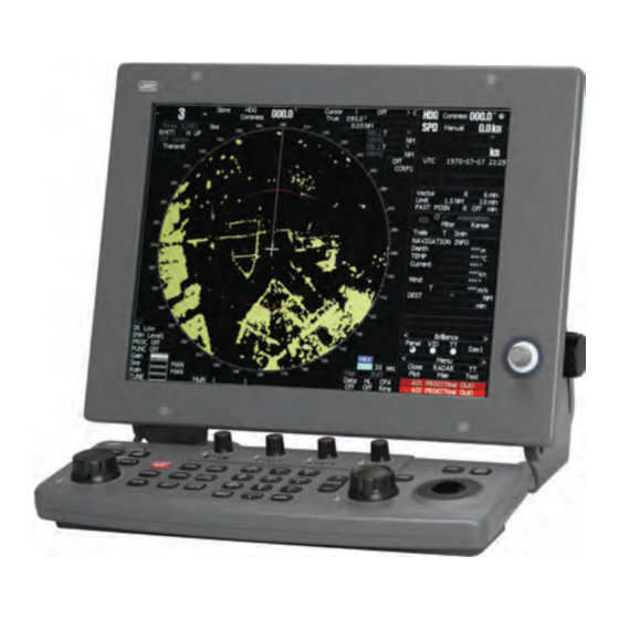
- Page 22 NDC-1460 Processor Unit (Desktop Type) NWZ-164 Display Unit (Desktop Type) NCE-7699A Operation Unit (Desktop Type) NCD-4380 Display Unit (Desktop Type) - xvi -...
-
Page 23: Table Of Contents
CONTENTS PREFACE........................i BEFORE OPERATION ...................ii PRECAUTIONS..................... iii THE MOUNTING POINT OF THE WARNING LABEL........... xi EQUIPMENT APPEARANCE ................xiv GLOSSARY ....................... xxvi 1. GENERAL AND EQUIPMENT COMPOSITION FUNCTIONS ................... 1-1 1.1.1 Function of This System ..............1-1 FEATURES ..................... 1-2 CONFIGURATION .................. - Page 24 2.3.6 Software Buttons for Area 6 (Other Ship Information Area) (Right Side of the Radar Display) ..2-16 2.3.7 Software Buttons for Area 7 (Panel Display Area) (Right Side of the Radar Display) ....2-18 2.3.8 Software Buttons for Area 7 (Panel Display Area) (Right Side of the Radar Display) ....
- Page 25 3.6.4 Clear Own Ship’s Track Data (Clear Own Track) ......3-78 DISPLAY CHARTS ................3-79 3.7.1 Insert/Remove a Card............... 3-79 3.7.2 Display Coastline ROM Card Produced by JRC ....... 3-81 3.7.3 Display ERC Card................3-82 3.7.4 Fill Charts (Fill Land Area) ..............3-83 DISPLAY NAVIGATION INFORMATION (NAV INFORMATION DISPLAY)............
- Page 26 3.8.4 Set Navigation Information (User Map Setting) ......... 3-92 3.8.5 Set and Display Geodetic System ............. 3-99 APPLIED OPERATIONS..............3-101 3.9.1 Set Radar Signal Processing (Process Setting) ......3-101 3.9.2 Set Radar Trails (RADAR Trails Setting) ......... 3-104 3.9.3 Set Cursor (Cursor Setting)............. 3-109 3.9.4 Set Screen(Screen Setting).............
- Page 27 TT OPERATION..................5-18 5.2.1 Acquiring Target [ACQ] ..............5-19 5.2.2 Canceling Unwanted Targets ............5-22 5.2.3 Tracking Target Data Display [TGT DATA] ........5-23 5.2.4 Displaying Target ID No. (Target Number Display)......5-25 5.2.5 Input of target information (TT Individual Setting) ......5-26 5.2.6 Reference Target (Reference)............
- Page 28 FALSE ECHOES ...................6-10 DISPLAY OF RADAR TRANSPONDER (SART)........6-13 7. SETTINGS FOR SYSTEM OPERATION SETTINGS AT INSTALLATION ............... 7-1 7.1.1 How to open the Adjust Menu ............. 7-2 7.1.2 Tuning Adjustment................7-3 7.1.3 Bearing Adjustment ................7-6 7.1.4 Range Adjustment ................7-7 7.1.5 Antenna Height Setting (Antenna Hight) ..........
- Page 29 7.5.3 Save of Internal Memory Data (Card2) ..........7-54 7.5.4 Update of Character String Data (String Data Update) ..... 7-56 7.5.5 Clear of Antenna Operation Time (TXRX Time CLR) ......7-57 7.5.6 Update of AIS Processor Program (AIS PROC Program Update) ..7-61 8.
- Page 30 DISPOSAL OF USED BATTERIES ............10-2 10.3 DISPOSAL OF USED MAGNETRON ........... 10-3 10.4 ABOUT THE CHINA ROHS..............10-4 11. SPECIFICATIONS 11.1 JMA-5208/HS TYPE RADAR ..............11-1 11.2 JMA-5212-4/6/4HS/6HS TYPE RADAR ..........11-2 11.3 JMA-5222-7/9 TYPE RADAR ..............11-3 11.4 SCANNER (NKE-2062)................. 11-4 11.5...
- Page 31 FIGURE 3 JMA-5212-4/6/4HS/6HS INTER-CONNECTION DIAGRAM FIGURE 4 JMA-5222-7/9 INTER-CONNECTION DIAGRAM FIGURE 5 PRIMARY POWER SUPPLY DIAGRAM, TYPE JMA-5208/HS, JMA-5212-4/6/4HS/6HS, JMA-5222-7/9 FIGURE 6 PROCESSOR UNIT, NDC-1460 INTER-CONNECTION DIAGRAM FIGURE 7 KEY-BOARD UNIT, NCE-7699A INTER-CONNECTION DIAGRAM FIGURE 8 NKE-2062 SCANNER UNIT INTERCONNECTION DIAGRAM...
-
Page 32: Glossary
GLOSSARY This section describes the main terms used for this equipment and general related maritime terms. Acquisition/Activation zone A zone set up by the operator in which the system should automatically acquire radar targets and activate reported AIS targets when entering the zone. - Page 33 CORRELation CORREL The distance to the Closest Point of Approach and Time to the Closest CPA/TCPA Point of Approach. Limits are set by the operator and are related to own ship. Course Through Water The direction of the ship's movement through the water The current velocity for manual correction or the current speed on the DRIFT horizontal axis of the 2-axis log is displayed.
- Page 34 InterSWitch A target symbol representing the last valid position of an AIS target Lost AIS target before the reception of its data was lost, or its last dead-reckoned position. One for which target information is no longer available due to poor, lost Lost tracked target or obscured signals.
- Page 35 Radar cross-section of a target determines the power density returned to Radar cross-section the radar for a particular power density incident on the target A set of concentric circles labeled by distance from CCRP. Range Rings A symbol indicating that the associated tracked stationary target is Reference target used as a speed reference for the ground stabilization The direction of motion of a target relative to own ship motion...
- Page 36 Speed Over the Ground The speed of the ship relative to the earth, measured on board of the ship. Short Pulse STABilization STAB Speed Through Water The speed of the ship relative to the water surface. Time to Closest Point of Approach to own ship TCPA Radar target of known characteristics used for test requirement Test target...
- Page 37 Variable Range Marker An adjustable range ring used to measure the distance to a target. A geographical location on a route indicating a event. Waypoint - xxxi -...
- Page 38 - xxxii -...
- Page 39 1 GENERAL AND EQUIPMENT COMPOSITION 2 SCREEN DISPLAY AND OPERATION PANEL 3 BASIC OPERATION 4 MEASUREMENT OF RANGE AND BEARING 5 OPERATION OF TT AND AIS 6 TRUE AND FALSE ECHOES ON DISPLAY 7 SETTINGS FOR SYSTEM OPERATION 8 MAINTENANCE AND INSPECTION 9...
- Page 40 - xxxiv -...
- Page 41 SECTION 1 GENERAL AND EQUIPMENT COMPOSITION FUNCTIONS ..........1-1 1.1.1 Function of This System...... 1-1 FEATURES ........... 1-2 CONFIGURATION ........1-4 EXTERIOR DRAWINGS....... 1-5 GENERAL SYSTEM DIAGRAMS ....1-15...
- Page 42 FUNCTIONS This equipment is a high-performance radar equipment consisting of a scanner unit, a transmitter-receiver unit and a high resolution color LCD display unit. 1.1.1 Function of This System The JMA-5200MK2 series is a color radar system designed to comply with the international standards of the IMO.
- Page 43 1.2 FEATURES FEATURES Realization of Easy-to-see Screen with High Resolution The 15-inch color LCD with high resolution of 1024 × 768 pixels can display radar images of 180 mm or more in diameter. Even short-range targets can also be displayed as high-resolution images. Target Detection by Latest Signal Processing Technology The system employs the latest digital signal processing technology to eliminate undesired clutter from the radar video signals that are obtained from the receiver with a wide dynamic range, thus improving the target...
- Page 44 Improved Day/Night Mode Two types of background colors are available in each Day/Dusk/Night mode (total 4 background colors). Each background color can be reproduced to be suited for the user’s operating environment by simple key operation. The radar echoes and a variety of graphics can also be represented in different colors, ensuring easy-to-see displays.
- Page 45 1.3 CONFIGURATION CONFIGURATION Scanners and Transmitted Output Powers TRANSMITTED RATE OF SCANNER TYPE BAND CATEGORY OUTPUT POWER ROTATION 4 FT SLOT JMA-5208 6 KW 27rpm ANTENNA 4 FT SLOT JMA-5212-4 10 KW 27rpm CAT 3 ANTENNA 6 FT SLOT JMA-5212-6...
- Page 46 EXTERIOR DRAWINGS Fig. 1.1 Exterior Drawing of Scanner Unit, Type NKE-2062/HS Fig. 1.2 Exterior Drawing of Scanner Unit, Type NKE-2103-4/4HS Fig. 1.3 Exterior Drawing of Scanner Unit, Type NKE-2103-6/6HS Fig. 1.4 Exterior Drawing of Scanner Unit, Type NKE-2254-7 Fig. 1.5 Exterior Drawing of Scanner Unit, Type NKE-2254-9 Fig.
- Page 47 1.4 EXTERIOR DRAWINGS Fig. 1.1 Exterior Drawing of Scanner Unit, Type NKE-2062/HS 1─6...
- Page 48 Fig. 1.2 Exterior Drawing of Scanner Unit, Type NKE-2103-4/4HS 1─7...
- Page 49 1.4 EXTERIOR DRAWINGS Fig. 1.3 Exterior Drawing of Scanner Unit, Type NKE-2103-6/6HS 1─8...
- Page 50 Fig. 1.4 Exterior Drawing of Scanner Unit, Type NKE-2254-7 1─9...
- Page 51 1.4 EXTERIOR DRAWINGS Fig. 1.5 Exterior Drawing of Scanner Unit, Type NKE-2254-9 1─10...
- Page 52 Fig. 1.6 Exterior Drawing of Monitor Unit, Type NWZ-164 1─11...
- Page 53 1.4 EXTERIOR DRAWINGS Fig. 1.7 Exterior Drawing of Processor Unit, Type NDC-1460 1─12...
- Page 54 Fig. 1.8 Exterior Drawing of Keyboard Unit, Type NCE-7699A 1─13...
- Page 55 1.4 EXTERIOR DRAWINGS Fig. 1.9 Exterior Drawing of NSK Unit, Type NCT-4106A 1─14...
- Page 56 GENERAL SYSTEM DIAGRAMS Fig. 1.10 General System Diagram of Radar, Type JMA-5208/HS Fig. 1.11 General System Diagram of Radar, Type JMA-5212-4/6/4HS/6HS Fig. 1.12 General System Diagram of Radar, Type JMA-5222-7/9 1─15...
- Page 57 AC100/110/115V 50/60Hz AC200/220/230V 50/60Hz Fig. 1.10 General System Diagram of Radar, Type JMA-5208/HS Note: Install the radar cable as far as from the cables of other radio equipment in order to prevent other radio equipment from interfering with the radar operations. In particular, do not install the antenna cable parallel to the cables of other radio equipment.
- Page 58 19 CORES COMPOSITE CABLE CFQ-6912(Max 65m) JRC supply Max Diameter 14.5mm Sub key-board (NCE-7699A/7729A) NDC-1460 Processor Unit (Simplified Inter-switch Operation) SCANNER NMEA input DLog etc. VIDEO JLR-10:CFQ-6934 (Option) KEY-BOARD JLR-20/30:CFQ-5469 (Option) Compass NMEA input (NMEA input) AIS/Dlog etc. COMPASS Gyro-Compass (sync/step)
- Page 59 HEATER CONTROL PART CIRCUIT BREAKER (5A) (SHIPYARD SUPPLY) 0.6/1kV-DPYCYS-1.5 0.6/1kV-DPYC-1.5 AC100V 50/60Hz 1φ 100W NBL-175 STEPDOWN TRANSFORMER 19 CORES COMPOSITE CABLE CFQ-6912(Max 65m) JRC supply Max Diameter 14.5mm 0.6/1kV-DPYC-1.5 SHIP'S MAIN Sub key-board (NCE-7699A/7729A) NDC-1460 Processor Unit (Simplified Inter-switch Operation) SCANNER NMEA input DLog etc.
- Page 60 1─19...
Need help?
Do you have a question about the JMA-5208 and is the answer not in the manual?
Questions and answers